Wood framing is the backbone of residential construction. It’s familiar, fast, and foundational. But here's the disconnect: most firms are still trying to manage wood framing construction with generic BIM workflows designed for steel and concrete. This isn't a software problem; it's a production and sequencing problem that quietly erodes margins on every project.
For US residential architects, production designers, and builders, the promise of BIM is clear: predictability, fewer RFIs, and protected margins. Yet, that promise often rings hollow because the digital workflow doesn't speak the unique language of wood. Let’s fix that.
The Disconnect: Why Generic BIM Fails Wood Framing
The root of the problem is simple but critical. Teams shoehorn wood framing into a one-size-fits-all BIM process, completely missing the detailed logic of how a wood structure is actually assembled. This creates a cascade of preventable issues that only surface in the field, triggering a flood of RFIs, rework, and schedule-killing delays.
It Starts with Schematic Models
The first failure point is the model itself. Too often, framing models are built schematically. They show general wall locations but lack individual studs, headers, or joists. For wood framing, a schematic model is just a pretty picture—it's not a buildable plan. This is where the chaos begins.
Without an accurate structural skeleton, MEP routing becomes a guessing game. Electricians and plumbers model their systems inside an empty shell, guaranteeing clashes with framing members that don't exist yet in the digital world. This is a systemic flaw that guarantees a storm of RFIs.
We’ve seen builders eliminate weeks of coordination chaos when structural and MEP teams agree on stud zones before modelling begins. This simple discipline shift moves coordination from a reactive exercise to a proactive strategy for protecting margins.
The Real-World Friction Points
When wood framed BIM models aren't managed with production maturity, the friction is felt directly on site. The whole point of BIM is to solve field problems before they happen, but a generic approach creates them instead.
Here are the common pain points that arise from this disconnect:
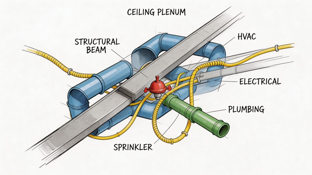
- MEP Penetration Chaos: Plumbing and electrical are routed through walls before stud locations are finalized, leading to inevitable clashes with king studs, cripples, and critical shear panels.
- Misaligned Bearing Walls: Schematic models fail to ensure load-bearing walls on different floors line up perfectly, a mistake that requires expensive structural fixes on the fly.
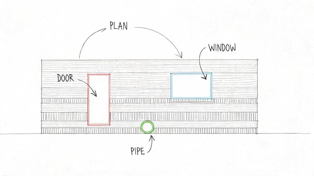
- Inaccurate Openings: Window and door rough openings are misaligned or sized incorrectly because the model never accounted for the actual header and sill details.
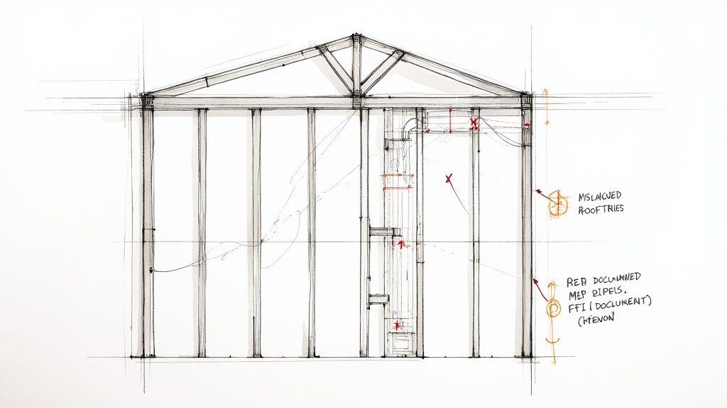
- Missing Hold-Downs: Critical structural connectors are overlooked in the model and missed during installation, only to be caught during a frame walk.
- Roof Truss Mismatches: Trusses arrive on-site, and only then does the crew discover they don’t align with the actual bearing points defined in the framing.
This isn't just about simple clash detection; it's about building a model that mirrors how a structure actually comes together. True residential BIM coordination for wood framing demands a workflow that respects its unique sequence. It requires template discipline, clear decision checkpoints, and a commitment to stud-level modeling to deliver the operational consistency every builder is fighting for.
Why Generic BIM Fails Wood-Framed Projects
Many firms jump into BIM hoping to lock in operational consistency and protect their margins. But when they apply it to wood framing construction, those goals often slip right through their fingers. The problem isn't the software itself—it's that they're using a playbook designed for steel and concrete on a material that follows completely different rules.
This "one-size-fits-all" BIM workflow just doesn't have the DNA to handle the precision and sequencing wood framing demands. It creates a fundamental mismatch that sends friction from the design phase straight to the job site. And it's not a small problem; with the wood framing sector projected to hit $31.5 billion by 2025, the cost of getting this wrong is a direct threat to profitability, especially as builders lean heavily on wood for single-family and multifamily projects. You can read more about the growth in the residential construction market and what it means for framers.
The Schematic Model Trap
The first and most common failure point is the model itself. Too often, teams will whip up a framing model to a schematic Level of Development (LOD 200). This shows basic wall locations, but it’s a ghost town—no individual studs, headers, or cripples are modeled. While that might be fine for high-level coordination in a steel building, it’s a recipe for disaster in wood framing.
This oversight triggers a painful domino effect. Without an accurate structural skeleton in the model, routing MEP becomes a complete guessing game. Plumbers and electricians start modeling their systems inside an empty shell, which inevitably leads to clashes with framing members that don't technically exist yet in the digital world. This isn't a minor hiccup; it's a systemic flaw that guarantees a storm of RFIs and forces expensive, last-minute fixes in the field.
The Sequencing Error That Bleeds Your Margin
The next critical breakdown happens with sequencing. In a disciplined workflow, the structural framing model should be almost entirely complete—with every stud layout defined—before the MEP modelers even touch their keyboards. Generic BIM processes throw this rule out the window, letting all trades work at the same time from a half-baked model.
This leads to some painfully predictable outcomes:
- MEP Penetration Chaos: A plumber routes a drainpipe right through a spot that needs a king stud or shear paneling. The framers get there and have to stop everything while someone figures out a reroute on site.
- Structural Integrity Risks: Field crews, trying to keep moving, just cut through studs or joists to make way for uncoordinated utilities. This compromises the building's load path and triggers a frantic call to the structural engineer for sign-off.
- Misaligned Components: Trusses show up on site and don't line up with the actual bearing walls, or window openings are framed wrong because the model never accounted for the real-world header and sill assemblies.
The core idea is simple: You can't coordinate what isn't modeled. Relying on schematic wood framed BIM models is like navigating without a map—you will eventually run into obstacles that should have been visible from the very beginning.
Real Consequences of Poor BIM Discipline
These aren't just theoretical problems. They are real-world costs that chew through project margins and obliterate any hope of a predictable schedule. We’ve seen entire projects get derailed by missing hold-downs that jeopardize structural integrity—issues that go completely unnoticed until a frame walk. When a generic approach to residential BIM coordination is used, the model stops being a tool for preventing RFIs and starts becoming the source of them.
When BIM practices are just ported over from steel and concrete projects, the model becomes a source of problems, not solutions. The table below breaks down exactly where these generic approaches go wrong for wood framing and how a specialized workflow turns things around.
Common Failures of Generic vs Wood-Specific BIM
| Friction Point | Generic BIM Approach (The Problem) | Wood-Specific BIM Workflow (The Solution) |
|---|---|---|
| Model Detail | Uses schematic LOD 200 models with empty walls. | Models to LOD 350, detailing individual studs, headers, and joists. |
| MEP Coordination | Allows MEP modeling to begin simultaneously with schematic framing. | Enforces a strict sequence: frame first, then coordinate MEP penetrations. |
| Issue Detection | Clashes are discovered on-site during framing or MEP install. | Clashes are identified and resolved digitally before materials are ordered. |
| Structural Integrity | Field crews cut structural members to fit uncoordinated MEP. | The model preserves structural zones, forcing MEP to route around them. |
| RFI Volume | Generates a high volume of RFIs related to framing conflicts. | Drastically reduces RFIs by providing a single source of truth for all trades. |
| Field Rework | Requires costly and time-consuming on-site modifications. | Minimizes field changes, protecting both the schedule and budget. |
This isn't just about better software; it's about a better process. A wood-specific workflow treats the digital model like a true rehearsal for construction, catching errors when they're cheap and easy to fix.
Ultimately, wood framing has its own language, and successful coordination is only possible when the digital workflow speaks it fluently. It demands stud-level modeling, strict rules for when trades can start their work, and a shared understanding that precision in the model is the only way to get predictability in the field. Anything less is just crossing your fingers and hoping for the best.
Building a Production-Ready Framing Model
Getting from chaos to clarity in wood framing construction means making a deliberate shift in how you build your models. A production-ready model isn't just a 3D picture; it's a digital twin of what's happening on-site, built with the same logical sequence a framer would use. This isn't about knowing software tricks—it's about baking production discipline into every click.
The whole process starts with a rock-solid set of templates. Generic, out-of-the-box templates are one of the biggest sources of problems down the line. A production-ready template, on the other hand, comes pre-loaded with the specific logic of wood construction. It enforces standards for stud layouts, header and sill details, and even carves out placeholder zones for common MEP runs before a single pipe is even modeled. This discipline is the first step toward getting consistency across all your projects.
Adopting Stud-Level Modeling
To get the precision you really need, the model has to be built out to a high level of detail—we're talking stud-level modeling. This means creating a model at what's often called LOD 350, where every single stud, joist, header, and cripple is its own distinct element. Those schematic models that just show wall masses? They’re useless for real coordination.
Modeling at this granular level is the only way to make BIM coordination for wood framing actually work. It turns the model from a rough architectural blob into an accurate structural assembly. This is the digital space where you can spot clashes with MEP systems and fix them before they turn into costly change orders on site. It’s the difference between finding a problem on a screen versus finding it with a saw in your hand.
A production-ready model is a system of rules, not just a collection of geometry. By defining these rules early through disciplined templates and modeling standards, you move from a reactive clash detection mindset to a proactive clash prevention strategy.
Establishing Clear Decision Checkpoints
A detailed model is only useful if it evolves in lockstep with every other discipline. Too often, the architectural, structural, and MEP models are developed in their own silos, which is a recipe for coordination disaster. The solution is to set up clear decision checkpoints—gates in the workflow where everything pauses until key decisions are aligned and signed off on by everyone involved.
These checkpoints make sure all teams are building from the same source of truth at every stage. For example, a non-negotiable checkpoint is locking in the structural framing layout before any MEP modeling begins. We’ve seen builders cut out weeks of coordination headaches just by getting structural and MEP teams to agree on stud zones before anyone starts modeling. This simple, process-driven checkpoint stops MEP designers from routing utilities through a schematic model, which is a massive driver of RFIs.
From Digital Picture to Digital Twin
The end goal is to create a model that serves as a reliable set of manufacturing instructions. This requires embedding real-world construction logic right into the digital process. For instance, your templates should include standard families for different wall assemblies, complete with accurate stud spacing, header setups, and even nailing patterns. Mastering the creation of these components is a big deal, and you can learn more about how to approach creating Revit families that enforce these standards.
The timber frame construction market is booming—it’s expected to grow to over $9.56 billion by 2032—and a lot of that growth is driven by this push toward precision and manufacturing-style assembly. Innovations in engineered wood like CLT are making this even more critical, since off-site fabrication demands a flawless digital blueprint. You can explore more data on the global rise of timber frame construction and its market forecast.
This level of detail in wood framed BIM models makes the model an incredibly powerful tool for pre-construction planning, permitting, and even buying materials. It gives you the clarity needed to protect your margins and deliver projects with a high degree of predictability. By focusing on templates, stud-level detail, and disciplined checkpoints, firms can transform their BIM from an aspirational tool into a core driver of production maturity.
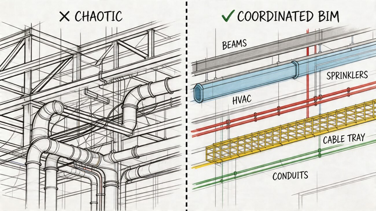
Systematic Coordination for Framing and MEP
Even the most meticulously crafted framing model can get completely derailed by the chaos of MEP (Mechanical, Electrical, and Plumbing) coordination. In wood framing construction, this is the single biggest source of RFIs—a friction point that bleeds margins and shatters schedules. Getting it right isn't about better software; it's about a systematic strategy that brings order to the chaos.
The core idea is simple: shift from being reactive to being proactive. Instead of chasing down clashes after they appear, a disciplined process prevents them from ever being modeled in the first place. It all starts by defining the rules of engagement before any trade even starts their work.
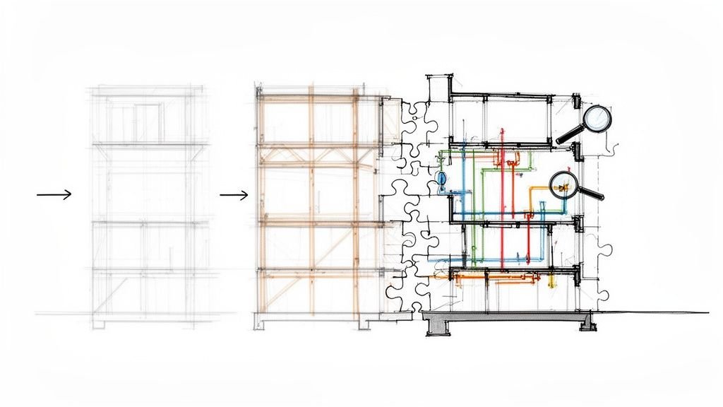
This diagram shows the basic, disciplined workflow for building a framing model that heads off coordination issues before they start.
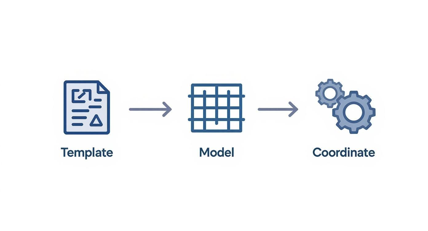
This process shows how starting with disciplined templates and building a detailed model turns the final coordination step into a simple verification exercise, not a painful discovery phase.
Establishing MEP Penetration Zones
The most powerful tactic here is to establish predefined MEP penetration zones directly within the structural model. These are agreed-upon, pre-approved areas inside wall cavities and floor systems where trades are allowed to route utilities without messing with the structure.
Think of them as highways for pipes and conduits. By defining these pathways early, you take all the guesswork out of it for the MEP designers. They're no longer navigating a minefield of king studs, shear walls, and bearing points. Instead, they have a clear map showing them exactly where they can—and cannot—go.
We’ve seen builders eliminate weeks of coordination chaos when structural and MEP teams agree on stud zones before modelling begins. This isn't just a best practice; it's a foundational rule for predictable delivery.
This approach requires one non-negotiable rule: no MEP element gets modeled until the stud zones and primary framing layouts are locked. This simple sequencing step ensures the structural model acts as the single source of truth, guiding MEP routing instead of just reacting to it.
From Clash Detection to True Coordination
Traditional BIM often gets stuck in a reactive loop of finding problems and then fixing them. While that's important, it’s a low-value activity compared to preventing those issues from the start. A mature residential BIM coordination process is built on sequencing and logic, not just geometry.
Here’s how this systematic approach solves common headaches:
- Bearing Wall Alignment: Predefined zones ensure MEP runs don't cut through critical load paths. The structural integrity is baked into the model from day one.
- Stud Layout Accuracy: With stud layouts finalized first, MEP designers can route utilities with precision, avoiding studs and minimizing the need for field fixes.
- Shear Wall Conflicts: Penetration zones are intentionally kept away from shear panels and hold-down locations, protecting the structural system from being weakened by last-minute cuts on site.
This transforms the model from a simple 3D drawing into a set of buildable instructions. It’s a huge step in moving from basic modeling to a mature, production-focused workflow. To get deeper into the mechanics of finding conflicts, our guide on BIM clash detection strategies provides great context on turning this into a proactive quality check.
Integrating Roof Truss Designs
The final piece of this coordination puzzle is the roof truss manufacturer. Truss misalignments are a constant source of field errors, usually because the truss design happens in a silo, completely disconnected from the primary wood framed BIM models.
A disciplined workflow closes this gap. The process should look like this:
- Provide the Baseline: The truss manufacturer gets the coordinated architectural and structural models. These clearly define all bearing points, roof planes, and potential MEP conflict zones in the attic.
- Receive and Integrate: The manufacturer sends back a detailed 3D model of their truss package. This isn't just a 2D layout; it's a model of the actual truss profiles and connections.
- Verify and Validate: This truss model is then brought into the master coordination model. Here, the team confirms that every truss lands perfectly on its bearing point and runs a final check for any clashes with attic-run HVAC or plumbing.
This integration ensures the trusses that show up on-site fit exactly as designed, killing the need for costly and structurally questionable field modifications. By treating wood framing with its own unique BIM language, you move coordination from a source of friction to a driver of predictability and profit.
Moving from Clash Detection to Clash Prevention
For way too long, the industry has seen BIM for wood framing construction as a reactive tool—something you use to find problems after they’ve already been designed in. But that’s a low-value game of digital whack-a-mole. The real win, the move that actually protects your margins and builds a repeatable process, is shifting from finding clashes to preventing them from ever happening.
This isn’t just a small tweak in your workflow. It’s a fundamental change in mindset, moving from seeing BIM as a simple 3D picture to using it as a system for predictable production. When you have a disciplined process, that model becomes a strategic asset for scaling your teams. It ensures every single project gets built to the same exacting standard, no matter who’s running it. This is how you kill the costly surprises that eat away at profitability.
The Model as a Permitting and Production Tool
One of the most overlooked perks of a well-coordinated model is its power during permitting. Building officials are just trying to verify code compliance, and a stack of unclear, schematic drawings is a recipe for long delays and endless questions.
But when you submit a plan set pulled directly from a stud-level model, everything changes. Bearing walls line up perfectly. Openings are precise. Every structural hold-down is explicitly shown.
This clarity does two things:
- It speeds up approvals. Officials can easily trace the load path and check code requirements, cutting down the back-and-forth that drags out review cycles.
- It builds confidence. A clean, detailed submission signals that you know what you're doing, establishing your firm as a mature and reliable partner.
This isn't just about getting a stamp faster. It’s about making sure the plans that get permitted are a true reflection of the final, coordinated structure you’re about to build.
Protecting Margins Through Process Discipline
Every RFI that comes back from the field is a direct hit to your bottom line. It’s unplanned labor, potential schedule slips, and a mountain of administrative overhead you didn’t budget for. At its core, a clash prevention strategy is really a margin protection strategy. By solving every coordination issue in the digital world first, you are systematically de-risking the entire construction phase.
The goal is to make framing on-site an act of assembly, not discovery. A disciplined wood framed BIM model ensures all the thinking, problem-solving, and coordination happens long before a single 2×4 gets cut.
This proactive approach is only becoming more critical. The global timber construction market is expected to explode, growing from USD 17.7 billion in 2025 to around USD 44.2 billion by 2035. This isn't just a trend; it's a massive shift toward sustainable, system-built methods that demand absolute precision. You can get more details on the future of the timber construction market on futuremarketinsights.com. The firms that master a production-level BIM workflow are the ones who will be positioned to grab that opportunity profitably.
From Aspirational Goals to Reliable Delivery
Ultimately, this isn't about selling drafting hours or showing off software skills. It’s about delivering clarity, systems, and reliability. When an architect or builder adopts a specialized BIM workflow for wood framing, they’re investing in a system that produces consistent, predictable outcomes every time.
This system is built on a few non-negotiable principles:
- Template Discipline: Locking in standards from the moment a project kicks off.
- Rigorous QA: Implementing model checks at key decision points, not just at the end.
- RFI Prevention: Designing workflows specifically to eliminate the common questions that come from the field.
By tying these detailed BIM practices to high-level business goals, you change the entire conversation. You’re no longer talking about building a better model; you're talking about building a better business. This is how you achieve true production maturity—where consistency and scalability aren't just goals, but the expected result of a well-run system.
Making the Switch to a Wood-Framed BIM Workflow
Shifting to a BIM process built specifically for wood framing construction isn’t about flipping a software switch overnight. It’s about building production maturity. The core idea is simple: treat wood framing with its own logic, focus on the process more than the tools, and coordinate everything from the stud level up. When you get this right, BIM stops being a reactive tool for fixing problems and becomes a proactive system for delivering projects reliably.
The good news? You don't have to tear down your current system to get started. It all begins with small, deliberate steps that build momentum and prove the value of a disciplined approach.
Your Path to Production Maturity
Don't try to change everything at once. The best way to get buy-in and work out the kinks is to run a controlled pilot project. This gives your team a low-risk environment to test, learn, and adapt the new workflow.
Here are a few practical first steps you can take:
- Develop a Basic Framing Template: Just start with one common wall type. Define your standard stud spacing, header details, and sill conditions. This simple template is the first building block for consistency.
- Establish a QA Process: A simple checklist for model reviews at key decision points is all you need. This makes sure your new standards are actually being met before the project moves forward.
- Run a Pilot Project: Pick a small, straightforward project to try out stud-level modeling and sequential MEP coordination. Make sure to track the reduction in RFIs—that data will build your business case for you.
This methodical approach isn't just about building better wood framed BIM models. It’s about building a scalable system that protects your margins and delivers predictable outcomes every time.
Making this transition work requires a clear roadmap. A well-defined strategy, like the ones laid out in a formal BIM Execution Plan, gets all stakeholders on the same page about processes, deliverables, and goals right from the start.
For a deeper dive and more best practices on running an effective wood framing BIM workflow, check out the excellent insights from the Timbercloud blog.
Ready to start building a more predictable delivery system? We’ve put together a Wood-Framed BIM Coordination Checklist to help you implement these foundational steps. Download it to begin your journey toward operational consistency and fewer surprises in the field.
Answering the Tough Questions
What LOD Do We Really Need for Wood Frame Coordination?
For genuine residential BIM coordination, your model has to hit a minimum of LOD 350. This isn't just about showing wall shapes; it means modeling every single stud, header, sill, and piece of sheathing.
A basic LOD 200 model that just shows wall masses is useless for coordination. MEP systems don't run through generic masses—they have to navigate around actual framing members. That’s where the clashes happen, and protecting your margins depends on seeing that level of detail from the start.
How Do You Handle Roof Trusses From a Third-Party Fabricator?
Success here comes down to two things: early coordination and strict process discipline.
First, you give the truss manufacturer the fully coordinated architectural and structural wood framed BIM models. In return, you must require them to deliver a detailed 3D model showing their exact truss profiles and layouts. This isn't a "nice to have," it's a non-negotiable.
Once you have their model, you federate it into your master file. This is where you verify all bearing points and connections and run one last clash detection against MEP before a single piece of wood is cut. This simple QA check catches massive field errors before they can cost you time and money.
What's the Single Biggest Mistake Firms Make With BIM for Wood Framing?
The most common—and most expensive—mistake is trying to force a BIM process designed for steel or concrete onto a wood-frame project. It just doesn't work.
This mistake leads to teams creating overly schematic models, letting MEP start modeling before the stud layout is even locked down, and just hitting the "clash" button without a real coordination strategy.
Real success in wood framing requires a workflow that’s built for its unique construction logic. Think of it as a production problem, not a software problem. Solving that puzzle is the only way to get predictable, profitable results.
Ready to build a more predictable and profitable delivery system? The team at BIM Heroes specializes in creating disciplined, production-ready BIM workflows that eliminate chaos and protect your margins.
Download our free Wood-Framed BIM Coordination Checklist to start implementing these foundational steps. This simple guide will help you begin the journey toward operational consistency and fewer surprises in the field. Get your checklist here.