Most coordination failures aren't the big, dramatic clashes discovered at the last minute. They’re the slow-burn result of small, misaligned modeling assumptions made in isolation, long before anyone thinks about writing an RFI. The common myth is that coordination issues are caused by late changes. The reality is that most are baked into the model from day one because of how structural framing is placed relative to architectural intent.
This is a guide for structural modelers, architects, and VDC teams who struggle with that misalignment. It’s a coordination accuracy guide, focused on the modeling decisions that either enable or break downstream documentation and construction.
Why Structural and Architectural Models So Often Collide
The real reason structural and architectural models clash isn’t a lack of skill or sophisticated software. It’s the failure to establish—and enforce—a shared set of rules from the very beginning. The disconnect starts quietly, with seemingly harmless assumptions that create a ripple effect, snowballing into major issues that blow up schedules and kill profit margins.
When the structural team models in a vacuum, their focus is on load paths and material efficiency. Meanwhile, the architectural team is zeroed in on spatial quality, finishes, and wall thicknesses. Without a common framework for datums, levels, and grids, these two valid perspectives are on an inevitable collision course.
The Cascade Effect of Misaligned Datums
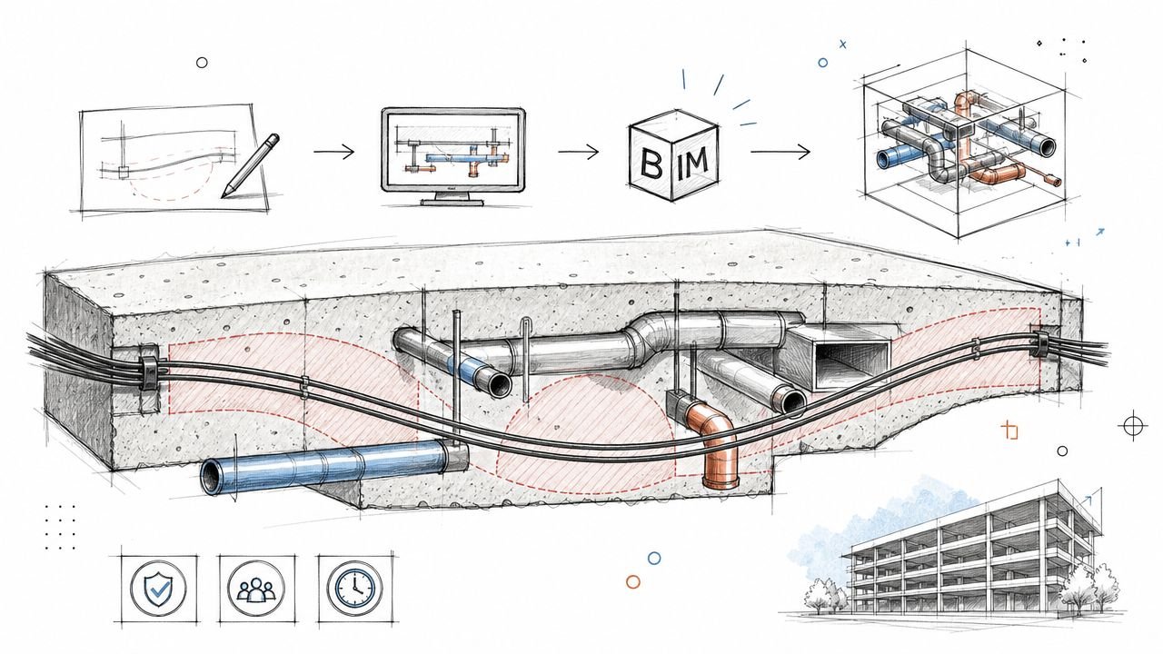
Think about a single structural column modeled just half an inch off the main architectural grid. Seems trivial, right? But that tiny drift means the façade panels no longer align. The ceiling grid now requires awkward cuts. And the main duct run, designed with tight tolerances, now clashes with the misplaced column.
That one early modeling assumption has now spawned a dozen downstream headaches. What comes next is a painful, predictable cycle:
- Repetitive Clashes: The same rogue column appears in every clash report, creating so much noise it’s impossible to spot the real problems.
- Constant Redraws: Teams waste hours tweaking their models to work around a foundational error that should have been prevented.
- Eroding Trust: Confidence in the models tanks. Soon, everyone defaults to manual field verification, which defeats the purpose of BIM.
The most expensive clashes aren’t the ones you find, but the ones you keep finding. They’re symptoms of a misaligned foundation, not a series of isolated mistakes.
Shifting from Reactive to Proactive Coordination
The only way to protect your margins and deliver projects predictably is to flip the workflow. Stop treating coordination as a cleanup task and start seeing it as a foundational strategy. This means getting obsessive about the critical-but-boring fundamentals first: shared datums, agreed-upon levels, and disciplined grid alignment. If you want to dive deeper into refining this workflow, you can learn more about practical strategies for BIM clash detection.
By building a rock-solid, shared foundation, you shift from reactive fire-fighting to proactive, controlled execution. This guide provides a practical framework for that foundation, ensuring your structural and architectural models finally work together.
Building a Bulletproof Foundation with Shared Datums
Successful structural modeling coordination is a direct result of discipline, not luck. Projects go off the rails when teams operate from separate sources of truth. A bulletproof foundation relies on establishing and respecting a single, authoritative set of shared datums from day one.
This means defining who "owns" the primary grids and levels—typically the architect—and ensuring every other discipline links to them. Period. The structural team’s job is not to create a competing system but to subscribe to the established one, monitoring it for changes without ever touching it directly. This simple rule prevents the model drift that causes endless downstream headaches.
To get started on the right foot, using technologies like 3D room scanning technologies can provide incredibly accurate as-built data, serving as a rock-solid shared starting point for all models.
Establishing Clear Ownership and Naming Conventions
The first step is to formally document datum ownership in the BIM Execution Plan (BEP). Any ambiguity here is a project killer. The BEP must state, in no uncertain terms, who creates, manages, and updates the core project datums.
Once ownership is locked in, naming conventions become critical. Vague level names like "Level 2" are insufficient. Use descriptive names that reflect real-world construction conditions:
- FFL-L02: Finished Floor Level – Level 02
- SSL-L02: Structural Slab Level – Level 02
- TOS-L02: Top of Steel – Level 02
This discipline removes guesswork. A structural modeler referencing "TOS-L02" knows exactly what that datum means, preventing the common mistake of framing to a finished floor level and creating instant clashes with the floor assembly.
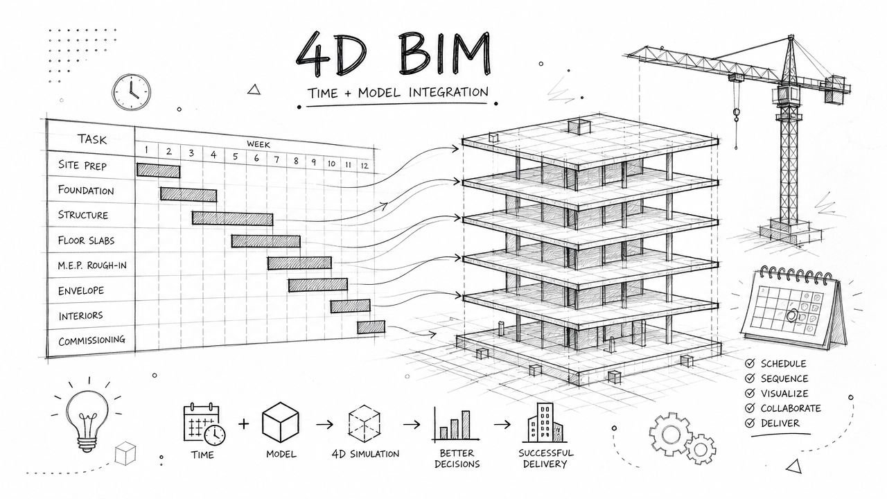
The infographic below shows how isolated modeling decisions become the root cause of coordination nightmares.
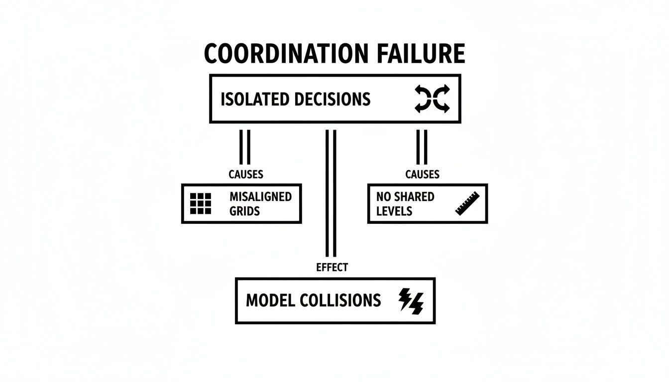
This visual makes it clear: costly model collisions aren't random. They are the predictable outcome of failing to lock down shared grids and levels from the beginning.
Establishing who owns what is foundational to preventing these issues before they start. The architect typically sets the stage, but every discipline plays a role in maintaining that single source of truth.
| Datum Ownership and Responsibilities | |||
|---|---|---|---|
| Datum Element | Primary Owner | Structural Team's Role | Common Failure Point |
| Project Grid System | Architectural Team | Link to and monitor the architectural grid; never create a separate one. | The structural team creates their own grid, leading to misalignment. |
| Primary Levels (FFL) | Architectural Team | Link to FFLs for reference, but model structure relative to structural datums (e.g., TOS). | Modeling structural elements directly to the finished floor level, ignoring slab thickness. |
| Structural Datums (TOS, SSL) | Structural Team | Create and manage structural levels, ensuring they are logically offset from architectural FFLs. | Poor communication about offsets, leading to vertical clashes. |
| Project Base Point/Survey Point | Civil/Survey Team | Link the architectural model to the established survey point to ensure site alignment. | Each model uses a different origin point, causing site coordination chaos. |
A well-defined ownership structure acts as the project's constitution. It provides clarity and holds each team accountable, ensuring everyone builds from the same playbook.
The Non-Negotiables: Grid and Level Discipline
With ownership and naming handled, execution comes down to rigorous technical discipline inside the Revit structural framing model. High-performing teams enforce a few non-negotiable rules to keep everything aligned.
First, all linked architectural grids and levels must be pinned immediately after being brought into the structural model. It's a simple click, but it prevents accidental movements that can throw the entire model out of whack. Second, using Scope Boxes consistently across all linked models ensures everyone is viewing and managing datums within the same boundaries, making discrepancies obvious.
A structural model's first job is to respect the project's coordinate system. Any deviation, no matter how small, introduces systemic error that ripples through every drawing sheet and fabrication model.
The final piece is implementing early-stage alignment checks. This isn’t a one-and-done setup; it’s an ongoing process. Teams should conduct weekly visual checks, overlaying models in dedicated coordination views to catch any drift before it gets baked into the design.
These simple, low-tech checks are often more effective at preventing major issues than waiting for complex, late-stage clash detection reports. This proactive approach to structural modeling coordination ensures the project starts on a stable foundation and stays there.
Modeling Structural Framing with Architectural Intent
Once grids and levels are locked in, the real work of structural modeling begins. But this is exactly where coordination often breaks down. Good bim modelling services aren't just about placing beams and columns for calculations; they're about modeling with constant awareness of the architectural vision—the volumes, finishes, and clearance zones that make a building usable.
The structural model must support the architecture, not fight it. Time and again, we see structural elements placed in a vacuum, creating a ripple effect of clashes with ceilings, façades, and MEP systems. This isn’t about last-minute changes causing chaos; it’s about early modeling decisions made without respecting architectural intent. The rule is simple: model it right the first time.
Avoiding Common Technical Failures
Most RFIs about framing clashes aren't complex engineering puzzles. They are the predictable outcome of basic modeling mistakes that ignore how buildings are actually assembled. These errors are sneaky because they look small on their own, but they create a cascade of rework that destroys productivity and margins.
Here are the most common technical failures we see in structural framing BIM models:
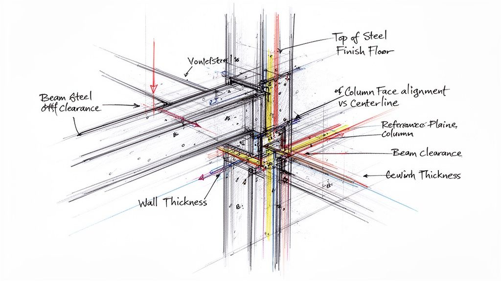
- Beams Modeled to the Wrong Datum: A classic. Placing the top of steel flush with the Finish Floor Level (FFL) without accounting for slab thickness or floor finishes. It’s a guaranteed clash with the architectural floor assembly.
- Columns Drifting Off-Grid: Modeling columns by snapping to an architectural wall centerline instead of locking them to the main structural grid. The moment an architect adjusts a wall thickness, that column moves, creating misalignment on every other level.
- Ignoring Architectural Zones: Running framing straight through areas clearly intended for ceilings, bulkheads, or major MEP runs. Without establishing clear "no-fly zones" early on, you’re just signing up for endless clashes.
- Inconsistent Offsets: Applying random or undocumented offsets from grid lines. This makes for an unreliable structural frame where nothing aligns logically, turning drawings into a mess.
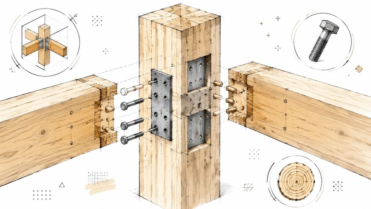
These aren't hypothetical problems; they are the daily grind for teams that don't make BIM structure and architecture coordination a priority. Every one of these slip-ups leads directly to redraws, wasted hours, and a model no one can trust. For a closer look at framing specifics, our guide on wood framing construction techniques offers more context on creating buildable models.
Modeling with Intent: Model This, Not That
Making the switch from reactive to proactive means changing how you think about placing every single element. Before modeling anything, you must ask, "What does this need to coordinate with?" This mindset is at the heart of effective structural modeling coordination.
The goal of a structural model isn't just to be structurally sound; it has to be architecturally compliant. If the framing makes the design impossible to build, the model has failed—no matter how efficient the steel tonnage is.
Here’s a practical look at how to model with architectural intent:
Model This
- Beams: Model the Top of Steel (TOS) to its own structural level, offset by a specific, agreed-upon distance from the architectural Finish Floor Level (FFL).
- Columns: Lock columns directly to the primary structural grids. Use reference planes inside the family to control their position relative to the grid, keeping them fixed even when architectural walls change.
- Bracing: Model bracing within clearly defined vertical zones agreed upon with MEP and architectural teams to steer clear of ductwork, conduits, and ceiling systems.
Not That
- Beams: Don't model the TOS directly to the FFL. This completely ignores the real-world thickness of slabs, toppings, and finishes.
- Columns: Don't snap columns to the centerline or face of an architectural wall. This ties the column's position to an element you have no control over.
- Bracing: Don't place bracing based only on structural efficiency without checking coordination views for clashes with other trades first.
The Power of Controlled Offsets and Reference Planes
The secret to keeping everything in line is the smart use of reference planes and controlled offsets within your Revit structural framing families and model. Instead of modeling elements face-to-face, you model them in relation to the shared datums—the grids and levels everyone agreed on.
Reference planes act as your control system. When you lock the core geometry of a column or beam to a reference plane that is also locked to a grid, you create a stable, predictable element. The architectural components can shift and evolve around it, but the structural frame stays exactly where it’s supposed to be.
This approach turns the model from a fragile collection of disconnected parts into a robust, rule-based system. It ensures the structural frame supports the architectural vision, not undermines it, and ultimately stops the endless cycle of RFIs and redraws that bleed projects dry.
Using Section Views as Your Primary Coordination Tool
Relying solely on automated clash detection reports is a reactive, inefficient way to coordinate. The software tells you what is wrong, but it rarely explains why. High-performing teams know the real secret to proactive coordination isn't buried in a clash report; it's found by creating and consistently reviewing dedicated section and elevation views.
This disciplined, visual approach is about preventing conflicts before they ever become formal clashes. Think of it as a real-time health check on your model's geometric integrity. By cutting sections through critical areas early and often, you visually confirm that the foundational rules of alignment are being followed. This hands-on method builds trust and ensures the model truly reflects design intent.
From 3D Clashes to 2D Verification
Automated clash detection is great for catching complex geometric overlaps, but it’s a terrible tool for verifying fundamental design rules. A beam modeled at the wrong elevation relative to a floor slab might not generate a "hard clash," but it’s a massive error that will cause headaches on site. Section views make these relational mistakes immediately obvious.
This approach shifts BIM structure and architecture coordination from a periodic software run to a continuous visual audit. It’s about building a habit of checking alignment in 2D, where the relationships between elements are crystal clear.
Your coordination views should be strategically placed to slice through high-risk areas:
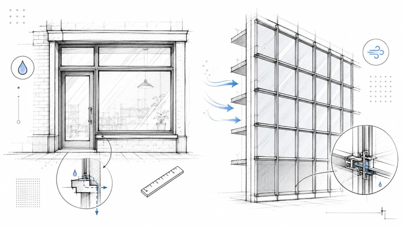
- Perimeter Conditions: Cut sections through the facade to verify beam-to-mullion clearances and slab edge alignment.
- Core Intersections: Create views showing column-to-wall junctions to ensure structural elements are neatly contained within architectural assemblies.
- Complex Geometries: Section through tricky spots like ramps, stairs, and vertical openings where multiple trades are fighting for space.
- MEP Headroom: Use key cross-sections to confirm that primary steel framing actually respects the required zones for ducts and other services.
Setting Up Effective Coordination Views
To make this work, these views must be simple and purposeful. They aren't working views cluttered with annotations or dimensions. The goal is clarity and speed, allowing any team member to instantly spot when something has deviated from the agreed-upon rules.
The most valuable coordination views are the ones that never make it onto a drawing sheet. They are production tools, used daily to confirm the geometric integrity of the model before detailing even begins.
A solid structural modeling coordination workflow uses these views to confirm specific rules. For instance, a quick check of a wall section can verify that a column is perfectly centered within a partition or that a beam's top of steel maintains the required 6-inch offset from the finished floor level. You can learn more about how detailed models are managed by reviewing different approaches to QA/QC in BIM.
Building Trust Through Visual Accountability
This method does more than just catch errors; it builds a culture of accountability and trust. When teams know their work is being visually verified in sections every day, the discipline of modeling to grids, datums, and offsets becomes second nature. The focus shifts from fixing clashes to preventing them in the first place.
This isn’t about micromanagement. It’s about making coordination transparent and collaborative. According to research from the National Institute of Standards and Technology (NIST), inadequate interoperability—a direct result of poor coordination—costs the U.S. capital facilities industry an estimated $15.8 billion every year. Using section views as your go-to coordination tool directly attacks the root cause of this waste.
Ultimately, this hands-on verification ensures that what is being modeled is actually buildable and aligned with architectural intent. It's a low-tech, high-impact process that guarantees your Revit structural framing model is a reliable asset, not a source of endless RFIs and costly field fixes.
Defining Clear Interface Zones and Rules of Engagement
Even with perfect datums, coordination can still fall apart without a formal agreement on how different building systems will interact. Just hoping for the best is a recipe for disaster. The solution is to lock down clear "Rules of Engagement" before heavy modeling begins, turning coordination from painful negotiation into a predictable, system-driven process.
This is all about defining the boundaries—the empty space between the modeled elements. By agreeing on specific zones for structure, architecture, and MEP systems, you create a rulebook that prevents collisions before they happen. This isn't a suggestion; it's a non-negotiable step for any team serious about getting work done efficiently and protecting project margins.
Establishing the Rules in a BIM Execution Plan
The best place to make these rules official is within the BIM Execution Plan (BEP). This makes them contractually relevant and accessible to everyone. The rules don't need to be complicated, but they must be specific and unambiguous.
Think of them as project-specific laws that govern the model:
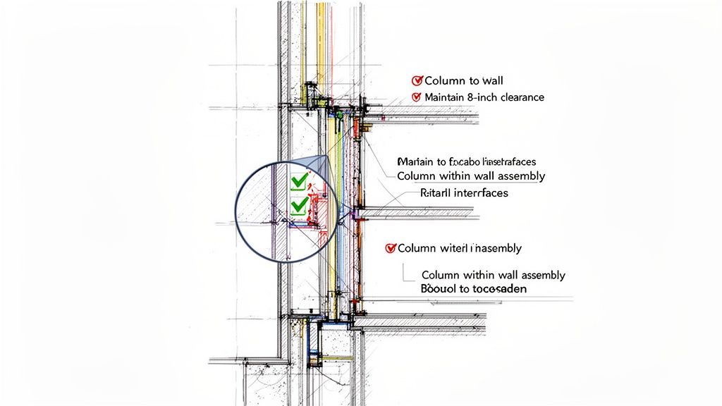
- Column Containment: All structural columns must be located entirely within architectural wall assemblies unless explicitly noted otherwise.
- Vertical Clearances: The top of primary structural steel shall maintain a minimum 8-inch clearance below the finished architectural ceiling plane.
- Horizontal Clearances: A 12-inch horizontal buffer zone must be maintained around all primary structural bracing for MEP routing.
- Facade Interface: The face of structural elements at the perimeter shall be offset a minimum of 6 inches from the interior face of the curtain wall mullion system.
When these rules are documented, they take the guesswork out of the equation and create a framework for accountability. Everyone models to the same set of constraints, making BIM structure and architecture coordination a matter of compliance, not constant arguments.
A project without defined interface zones isn't a collaboration; it's a turf war waiting to happen. Documenting the rules turns every modeler into a guardian of project-wide coordination.
This systematic approach is a core principle behind effective bim modelling services. The market for these services is growing fast precisely because this level of discipline delivers real results. The U.S. Building Information Modeling (BIM) market was valued at USD 3.10 billion in 2025 and is projected to skyrocket to USD 7.95 billion by 2033. This growth is fueled by the fact that outsourcing BIM modeling services can slash project timelines by up to 20-30% through clash detection and automated coordination, directly solving the biggest headaches in complex designs. You can find more details in this market analysis on snsinsider.com.
From Ad-Hoc Fixes to System-Driven Predictability
Without these rules, every interaction between trades becomes a custom negotiation. The architect moves a ceiling, and suddenly the structural team has to reroute bracing. MEP needs a larger duct run, forcing a change to beam depths. This constant back-and-forth is where schedules slip and budgets get blown.
Defining engagement rules upfront prevents this chaos. It forces critical design decisions to happen early, when the cost of change is low. When every team member understands the spatial "contract" they are working under, the entire process becomes more predictable and efficient. This level of foresight is crucial, especially when deciding on the right amount of information for different project stages. To get a better handle on this, check out our guide on BIM Level of Detail (LOD).
Ultimately, establishing these rules is about creating operational consistency. It ensures that the structural framing BIM model and the architectural model can be developed in parallel with confidence, knowing that the defined buffer zones and clearance requirements will keep them from colliding. This proactive strategy is the hallmark of a mature, professional production workflow.
A Framework for Predictable Coordination
Good coordination isn't an accident. It’s the direct result of a disciplined process and clear communication—not luck or last-minute software heroics. The path to reliable delivery and protected margins is paved with deliberate, foundational choices made long before the first RFI is ever written.
This guide boils down to a few core principles that form the bedrock of a mature production workflow. These are field-tested rules that separate predictable projects from chaotic ones. They create a system that delivers consistency, turning coordination into a managed process rather than a constant firefight.
Your Core Takeaways
- Own the Datums: You absolutely must establish a single source of truth for all grids and levels, with clear ownership defined in the BEP. This is non-negotiable.
- Model with Intent: Every structural element must be modeled with constant awareness of the architectural finishes, zones, and clearances that surround it.
- Use Sections for Verification: Get proactive. Use dedicated coordination sections to visually confirm alignment early and often. Don't wait for a clash report to tell you something's wrong.
- Define the Rules: Document clear interface zones and rules of engagement. This eliminates ambiguity and prevents turf wars between trades down the line.
True project predictability doesn't come from advanced software. It comes from the consistent application of a simple, robust framework that every person on the team understands and respects.
Ultimately, this framework transforms bim modelling services from a commodity into a strategic advantage. It shifts the focus from selling hours to delivering clarity and reliable outcomes. For this to work, teams also have to get exceptionally good at mastering action items on meeting minutes, making sure every decision leads to tangible progress.
To help you put these principles into practice on your next project, we've put together a detailed checklist. It’s a practical tool designed to help your team implement the workflows we've talked about here.
Download our free Structural–Architectural Coordination Checklist to build a more predictable, profitable, and collaborative project workflow.
Frequently Asked Questions
Let's dig into some of the practical questions that come up every day for structural modelers, BIM coordinators, and VDC teams. These are the real-world issues that can make or break a coordination workflow, and the answers here are all about providing clear, actionable advice.
Who Is Responsible for Managing Shared Coordinates and Levels?
In almost every project, this responsibility falls to the architectural team. They're the ones defining the building's overall massing and floor elevations, so it's only natural they establish the primary project datums like grids and levels. The structural team’s job is to link to these elements, not create their own versions.
A well-written BIM Execution Plan (BEP) should make this crystal clear by assigning "ownership" of these datums. The goal is to prevent any confusion down the line. Think of it this way: the structural model should subscribe to the architectural coordinates. This single source of truth is the absolute bedrock of successful BIM structure and architecture coordination.
What Is the Best Way to Handle Architectural Wall Thickness Changes?
This is a classic coordination headache. The most reliable way to handle it is to model your structural columns based on grid lines and agreed-upon offsets—never snap them directly to architectural wall faces. A good practice is to use reference planes within your column families and lock those planes to the grids.
Why? Because when an architect inevitably changes a wall from 6 to 8 inches, your column's location remains fixed relative to the grid. The change gets flagged during visual checks in section views, turning it into a deliberate decision rather than an accidental model shift. This simple discipline prevents columns from 'drifting' off the primary structural grid.
How Early Should We Create Coordination Section Views?
Immediately. As soon as the initial massing and structural framing BIM grid are in place, start cutting sections. This should happen during the Schematic Design (SD) phase. Don't wait for Design Development (DD), when every change is exponentially more expensive to fix.
Create a set of simple, non-annotated 'working sections' at key locations like the building perimeter, core, and any complex intersections. These aren't meant for official documentation. Their only job is to provide a quick, visual check on the fundamental alignment between the structural and architectural models from day one.
These early, simple visual checks can prevent the vast majority of alignment problems that surface later, when they are far more expensive and time-consuming to fix. They are a core part of any mature production workflow.
Making a habit of checking these views weekly is one of the most effective ways to ensure your BIM modeling services deliver a reliable and coordinated product.
At BIM Heroes, we help firms implement disciplined workflows that deliver clarity and predictable outcomes. To start building a more reliable coordination process on your next project, download our free Structural–Architectural Coordination Checklist.