A fully coordinated Revit model represents a powerful starting point, not a finished product ready for the factory floor. The promise of BIM is that this digital asset will translate seamlessly into fabrication-ready shop drawings. Yet, this critical handoff is precisely where projects either gain a decisive advantage or quietly accumulate errors, rework, and margin erosion. The gap between a designer's LOD 350 Revit model and a fabricator's required LOD 400 detail is where BIM's promise either succeeds spectacularly or fails quietly.
This isn't an abstract workflow diagram. This is a concrete, step-by-step workflow example showing exactly how a Revit model transforms into fabrication shop drawings. We'll show what happens at each stage, who's responsible, and where the process typically breaks down. The reality is that "fully coordinated BIM model" often still requires fabricators to remodel from scratch because the design model wasn't built for manufacturing. The difference comes down to understanding LOD requirements, fabrication modeling standards, and the distinct roles of design models vs. fabrication models.
Why This Workflow Matters: Margin, Predictability, and Quality
A disciplined Revit-to-fabrication workflow isn't an academic exercise; it's a direct path to margin protection and operational consistency. When this handoff fails, fabrication teams remodel from scratch, design models lack sufficient detail for manufacturing, and coordination models hide missing connections and dimensions. This chaos leads to RFIs, schedule delays, and eroded profits.
In contrast, an optimized workflow delivers tangible results. We've documented workflows where the Revit-to-fabrication handoff reduces shop drawing production time from three weeks to one week. Model-based shop drawings can cut drafting time by 40-60%, and extracting 2D views from a 3D model ensures absolute consistency. This is how you move from aspirational BIM to reliable delivery.
The Complete Pipeline: Design Model to Fabricated Component
The journey from Revit to the shop floor is a multi-phase process involving distinct teams, software, and levels of detail. It is not a simple file export but a structured handoff of information.
Phase 1: Design Model Development (Architect/Engineer)
The process begins with the design team creating the design-intent model, typically in Revit. The goal here is not to detail for fabrication but to create a model that fabricators can actually use as a reliable starting point.
- LOD Requirements: The target is typically LOD 300-350. For a steel frame, this means all primary members are modeled to their correct size and location. For MEP, it means major duct and pipe runs are routed with accurate dimensions. Generic connections are acceptable, but spatial allowances must be accurate.
- Modeling Standards: The model must be clean. Elements should be modeled with the correct families and categories. Worksets must be organized logically. This discipline is essential for the fabricator to isolate and work with specific scopes.
- Embedded Information: Critical design information must be embedded. This includes material specifications, performance requirements, and design loads. A beam object should contain its grade and size, not just its geometric shape.
Phase 2: Coordination Model Development (BIM/VDC Team)
The VDC team takes individual design models from all trades and federates them into a master coordination model, usually in Navisworks. This phase is about spatial validation before the handoff.
- Clash Detection: The primary task is running interference checks to resolve clashes between trades (e.g., a duct hitting a beam).
- Spatial Coordination: This goes beyond simple clashes. It verifies that there is adequate space for installation, maintenance access, and code-required clearances. For example, ensuring an electrical panel has its required 36" of clear space.
- System Validation: The VDC team confirms that systems are logically complete and spatially viable. This is the last checkpoint before the model is issued to fabricators for detailing.
Phase 3: Model Handoff to Fabricator
This is the most critical checkpoint. It's not a file transfer; it's a structured information exchange. A breakdown here guarantees rework.
- File Formats: Native Revit files (RVT) are often preferred, but IFC or even DWG exports may be used depending on the fabricator's software ecosystem. The format must be agreed upon beforehand.
- Model Preparation: Before sending, the model must be cleaned. Purge unused elements, remove unnecessary views, and audit the file for errors. Include only the scope relevant to that specific fabricator.
- Information Package: The handoff includes more than the model. It must be accompanied by the relevant 2D contract drawings, specifications, cut sheets for purchased equipment, and any approved submittals.
- Handoff Meeting: A kickoff meeting is essential to align expectations. The design team, VDC coordinator, and fabricator's detailer review the model together, confirm LOD, and clarify any ambiguous areas.
Phase 4: Fabrication Model Development (Detailer/Fabricator)
The fabricator's detailer takes ownership of the design model and begins advancing it to a fabrication-ready state. This is where design intent becomes a manufacturing plan.
- Software Transition: This often involves moving from Revit to specialized fabrication software. For steel, it's Tekla or SDS/2. For MEP, it might be Revit with fabrication parts or Fabrication CADmep.
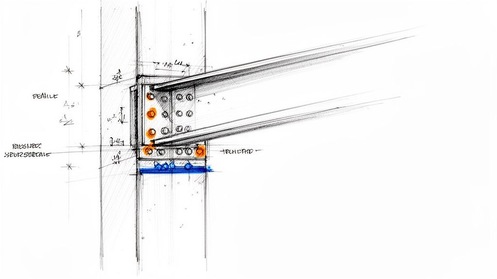
- LOD Advancement to 400: This is the core of fabrication modeling. The detailer replaces generic elements with fabrication-specific ones. A generic beam-column connection becomes a specific bolted end plate connection with actual bolts, welds, and plate thicknesses. A general pipe run gets populated with specific valves, flanges, and hangers.
- Adding Fabrication-Specific Information: The detailer adds information required for the shop floor: part numbers, material stock lengths, weld symbols, and assembly marks. They also adjust the model to reflect their shop's specific capabilities and constraints.
Phase 5: Shop Drawing Production
With a complete LOD 400 fabrication model, creating the 2D shop drawings becomes a process of extraction, not manual drafting. This is a key efficiency gain of the BIM to fabrication workflow.
- 2D Extraction: Views (plans, elevations, sections, isometrics) are generated directly from the approved 3D model. This ensures consistency between all drawings and the model.
- Dimensioning and Annotation: The detailer adds dimensions, notes, schedules, and labels required by the shop. This includes bolt lists, material cut lists, and assembly instructions.
- Shop-Specific Information: Each drawing is formatted to match the shop's standards, including title blocks, drawing numbers, and revision tracking.
Phase 6: Shop Drawing Review and Approval
The completed shop drawings are submitted back to the design team (Architect/Engineer) for review.
- Design Intent Compliance: The engineer reviews the drawings to confirm they accurately reflect the design intent and meet all structural and performance requirements.
- Coordination Verification: The drawings are checked against other trades' submittals to ensure a final layer of coordination.
- Approval Process: The drawings are returned with a status: "Approved," "Approved as Noted," or "Revise and Resubmit." This cycle may repeat, but a well-executed workflow minimizes revisions.
Phase 7: Fabrication and As-Built Loop
Once approved, the shop drawings and the underlying fabrication model are released to the shop floor.
- Model-Driven Fabrication: Modern shops use the 3D model data directly to drive CNC machinery like beam lines, plasma cutters, and automated duct coil lines.
- Field Verification: The installation team uses the shop drawings for assembly. Any deviations or field-required changes are documented (red-lined).
- As-Built Documentation: The red-lined changes are fed back to the detailer, who updates the fabrication model to reflect the as-built condition. This closes the loop and provides an accurate asset for the building owner.
Workflow Example: Structural Steel Fabrication
Let's apply this workflow to a structural steel package.
- Design Model (Engineer): The engineer models the primary steel frame in Revit (LOD 350). All beams and columns are correctly sized and located. Connections are shown generically, perhaps as simple symbolic lines, but enough space is allocated for the real connection.
- Coordination (VDC): The steel model is federated with MEP and architectural models in Navisworks. A clash is found where a large duct passes through the web of a primary girder. The VDC manager flags this.
- Resolution: The engineer and MEP designer coordinate. The engineer agrees to add a 24"x24" web penetration to the girder in the Revit model. The design model is now coordinated for this issue.
- Handoff (Fabricator): The steel fabricator receives the updated Revit model, contract drawings, and specifications. In a kickoff meeting, they confirm that all web penetrations required by other trades have been identified and modeled.
- Fabrication Modeling (Detailer): The detailer imports the Revit model into Tekla Structures. They convert the generic Revit elements into Tekla objects. They replace the generic connections with detailed, bolted shear tab connections, modeling every plate, bolt, and weld. The engineer-defined web penetration is framed out with stiffener plates per AISC standards.
- Shop Drawing Production: From the completed Tekla model, the detailer generates all required drawings: anchor bolt plans, erection drawings showing piece marks, and assembly drawings for each beam and column. A bill of materials is automatically generated from the model data.
- Approval & Fabrication: The drawings are submitted to the engineer, who reviews them for compliance with their design calculations. Once approved, the NC files from the Tekla model are sent directly to the CNC beam line in the shop for automated cutting and drilling.
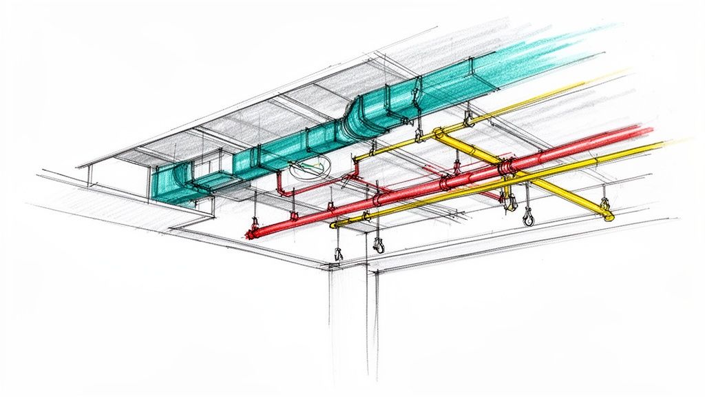
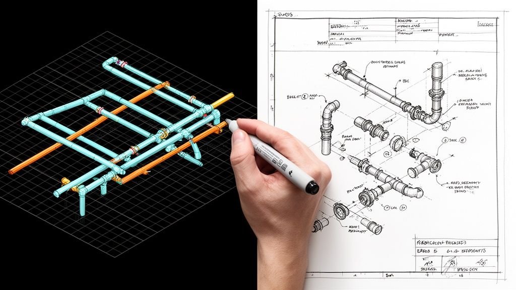
This same workflow applies across trades, with variations in software and specific details. For MEP, Revit's fabrication parts are used to add hangers, supports, and fittings. For precast concrete, the detailer adds reinforcement, lifting hardware, and connection plates. The core process of advancing a coordinated design model to a detailed fabrication model remains the same. Understanding the nuances of these trade-specific requirements, such as those in complex panel fabrication workflows, is key to successful implementation.
Common Breakdowns and How to Prevent Them
- Failure: The design model is "thrown over the wall" without a proper handoff meeting.
- Solution: Mandate a kickoff meeting for every fabrication scope. Use a checklist to review model cleanliness, LOD, and included documentation.
- Failure: The fabricator remodels from scratch because the design model is untrustworthy or unusable.
- Solution: The design team must adhere to strict modeling standards. Establish a BIM Execution Plan (BEP) that defines these standards for all parties.
- Failure: Shop drawing review becomes a bottleneck with endless revision cycles.
- Solution: Involve the fabricator early in the design process. Their input on constructability and connection design can resolve issues long before the submittal stage.
- Failure: The 2D shop drawings don't match the 3D fabrication model.
- Solution: Enforce a "model-first" rule. All 2D views must be extracted directly from the 3D model. Manual 2D drafting should be prohibited for any geometry shown in the model.
Quick Reference: Model Handoff Requirements Checklist
Use this checklist to ensure a clean handoff from the design/VDC team to the fabricator:
- Model Audit: Has the model been audited, purged, and cleaned?
- Scope Defined: Is the fabricator's scope of work clearly isolated in the model?
- Supporting Documents: Are all relevant contract drawings, specs, and cut sheets included?
- Coordinate System: Has the shared coordinate system been confirmed?
- LOD Agreement: Is there written agreement on the LOD of the received model?
- Handoff Meeting: Has a kickoff meeting been held with all key stakeholders?
- File Formats: Have the required file formats and software versions been confirmed?
From Workflow to System: The Path to Predictability
The path from a Revit model to a fabrication shop drawing isn't automatic—it's a multi-stage workflow requiring specific standards, clear handoffs, and distinct roles for design, coordination, and fabrication modeling. The answer isn't assuming Revit models are fabrication-ready; it's building a deliberate system that bridges design modeling and real-world manufacturing requirements.
The difference between projects that struggle and those that succeed often comes down to production maturity. High-performing teams don't rely on heroics; they rely on documented, repeatable processes. They build systems that ensure clarity at every decision checkpoint, preventing RFIs and protecting margins. By establishing clear Standard Operating Procedures (SOPs), you transform tribal knowledge into a scalable asset. The reader who finishes this should feel that "these people understand production better than most firms."
This detailed workflow provides the framework. Implementing it requires discipline, but the outcomes—predictability, quality, and profitability—are the core of reliable project delivery.
If your team is ready to build a reliable, scalable production system that bridges the gap between design and fabrication, our Model Handoff Requirements Checklist can provide the guardrails you need. Download our Revit-to-Fabrication Handoff Checklist to start implementing these quality control checkpoints on your projects today.