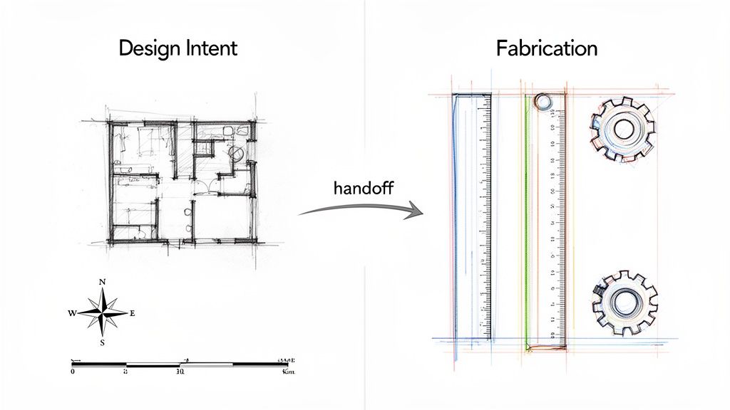
Think of it this way: construction drawings define intent, while shop drawings define execution. Projects run smoothly only when both are clearly understood and correctly aligned. The difference isn't just academic; misunderstanding the handoff between them is one of the biggest sources of friction, RFIs, and margin erosion in modern construction.
This isn't about simplistic definitions. It's about explaining the difference as it plays out on real projects, where confusion over roles, responsibilities, and the level of precision causes real pain. Let's break down how these two distinct but tightly connected stages of the information flow should work.
Design Intent vs. Fabrication Execution: Why the Handoff Matters
Every project transforms from an idea into a physical reality. Construction drawings and shop drawings are two separate, crucial checkpoints in that journey. They represent a critical handoff from the design team, who defines the project's requirements, to the fabrication teams, who translate those requirements into buildable components.
When the line between them blurs, things go sideways. Contractors fabricating from permit drawings, architects over-detailing construction documents (CDs), and shop drawings that don’t align with the architectural model all lead to the same result: a messy flood of RFIs, expensive rework, and shrinking profit margins. This isn't about incompetence—it's a breakdown in process.
Source of Confusion: Detail vs. Responsibility
At a glance, it's easy to see why teams get confused. Both sets of drawings are technical and detailed. But the why behind them—and the level of dimensional certainty they provide—is completely different.
- Construction Drawings (CDs): Created by the architect and engineers, these documents communicate the design intent, scope, performance specifications, and compliance with building codes. They answer the question: "What are the requirements for this part of the building?"
- Shop Drawings: Created by the subcontractor, fabricator, or supplier, these documents translate the design intent into a precise, fabrication- and installation-ready guide. They answer the question: "How are we going to make this specific component to meet those requirements?"
This handoff is a planned checkpoint, not a flaw. Construction drawings intentionally stop short of dictating exact fabrication methods. This allows specialty fabricators to apply their own systems, templates, and production expertise, which is fundamental to competitive bidding and quality execution. We’ve seen coordination cycles shorten when teams clearly define where construction drawings end and shop drawings begin.
Construction Drawings: Defining the "What" and "Why"
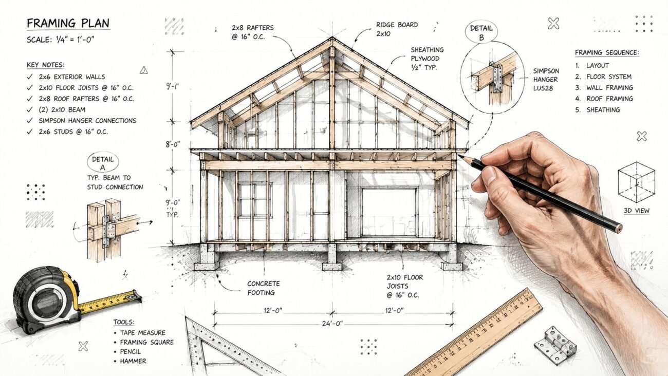
Construction drawings—often called CDs or permit drawings—are the authoritative source of design intent. They are the legal and contractual blueprint outlining the project's scope, performance specs, and code compliance. Think of them as the master plan: they tell everyone what needs to be built and where it goes, but they deliberately stop short of dictating how.
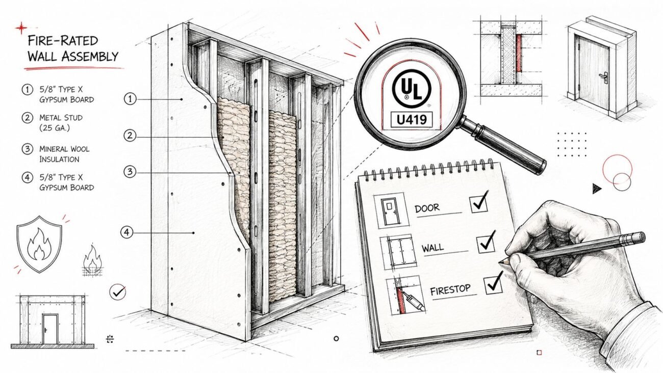
This is a feature, not a bug. A common pain point arises when a fabricator expects CDs to contain every last detail needed for assembly. But architects stop short of fabrication detail by design to avoid taking on unnecessary liability and to allow trade partners to leverage their specific expertise. The architect’s job is to define the performance criteria—a wall's fire rating, a curtain wall's wind load capacity—creating a "sandbox" for fabricators to work within.
The Strategic Limit of Detail: LOD and Liability
A solid set of construction drawings provides just enough information to price the job and understand the scope. Over-detailing CDs can create significant risk. If an architect specifies a particular connection method that later proves inefficient or fails, the liability could swing back to them.
This is where the concept of Level of Development (LOD) becomes critical. Most CDs target LOD 300 or LOD 350, which is the sweet spot for communicating intent without overstepping into fabrication means and methods.
- LOD 300: The model element is graphically represented with specific quantity, size, shape, and location.
- LOD 350: This adds detail on how the element interfaces with other components, showing critical coordination points.
Sticking to this scope keeps the design team in their lane and gives the fabrication team the flexibility to use their own proven production methods. It's a win-win that protects margins and promotes operational consistency.
Shop Drawings: Translating Intent into the "How"
If construction drawings set the rules, shop drawings are the playbook for execution. This is where high-level design intent gets translated into the precise, actionable instructions needed to build, assemble, and install a component. The shop drawings meaning is about translation and planning, not redesigning.
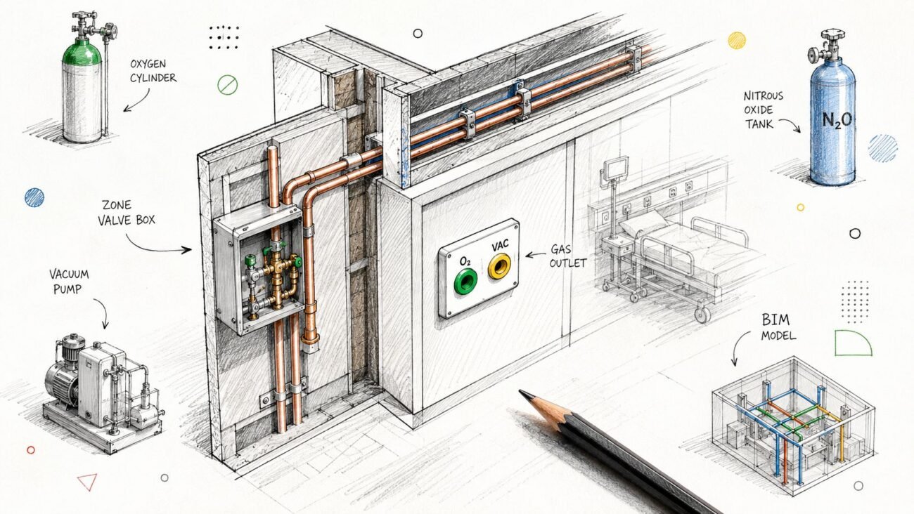
These documents come from the trade specialists—steel fabricators, millworkers, MEP contractors—and reflect their unique systems. They take the performance requirements from the CDs and detail exactly how their team will meet them.
From General Intent to Fabrication-Ready Detail
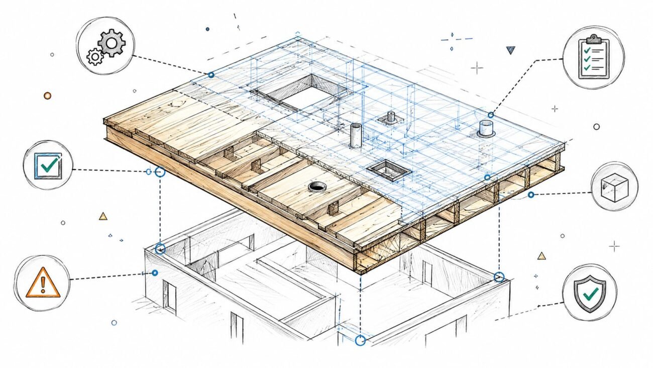
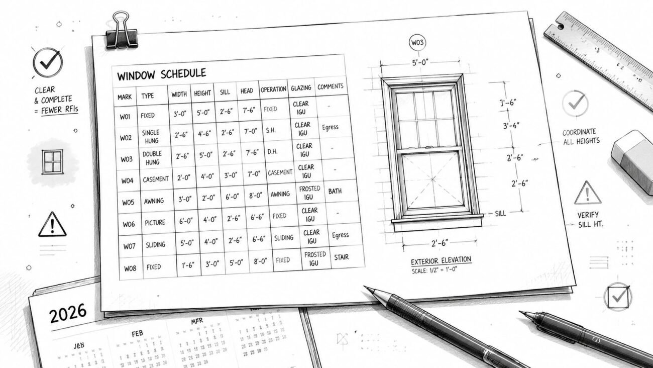
Construction drawings might specify a beam's location and load capacity. The corresponding BIM shop drawings must define its exact length, bolt hole locations, weld types, and surface finish. They close the information gap by nailing down details like:
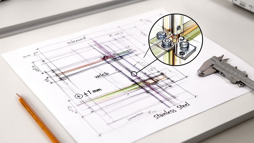
- Dimensional Certainty: Precise, field-verified measurements that replace the nominal dimensions found in design drawings.
- Tolerance Control: Specific allowances for variation, ensuring components fabricated off-site will align perfectly during installation.
- Material Specificity: Exact grades, finishes, and supplier information, moving from a general spec to a purchase-order-ready list.
- Connection Logic: Detailed joinery, welds, bolt patterns, and assembly hardware that illustrate precisely how parts connect.
This level of detail makes the shop drawing a crucial decision checkpoint. It’s the fabricator’s way of confirming, “This is exactly how we plan to fulfill your design intent. Please review and approve before we cut material.” This QA process is the single most effective way to prevent RFIs and protect project margins.
Practical Distinctions That Matter in Production
Let's move past textbook definitions. The real difference between construction drawings and shop drawings plays out where friction happens: on the job site and in the fabrication shop. Problems arise not because one set is “wrong,” but because teams are working from different assumptions about precision, responsibility, and detail.
Dimensional Certainty: Nominal vs. Actual
Construction drawings use nominal dimensions to establish scope, location, and relationships between elements. They are perfect for design intent and bidding. Shop drawings, however, demand absolute dimensional certainty based on as-built conditions.
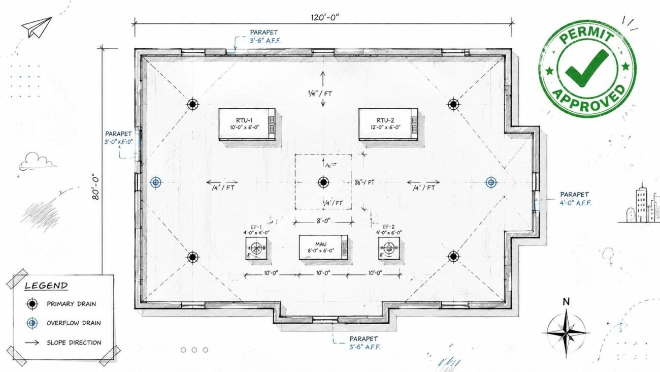
- Construction Drawing: Shows a 10-foot opening for millwork.
- Shop Drawing: Uses a field-verified measurement of 9' 11 ⅞" and details every component to fit that exact space.
Fabricating from nominal dimensions is a recipe for rework. The shop drawing process forces the translation from nominal to actual, acting as a critical QA checkpoint.
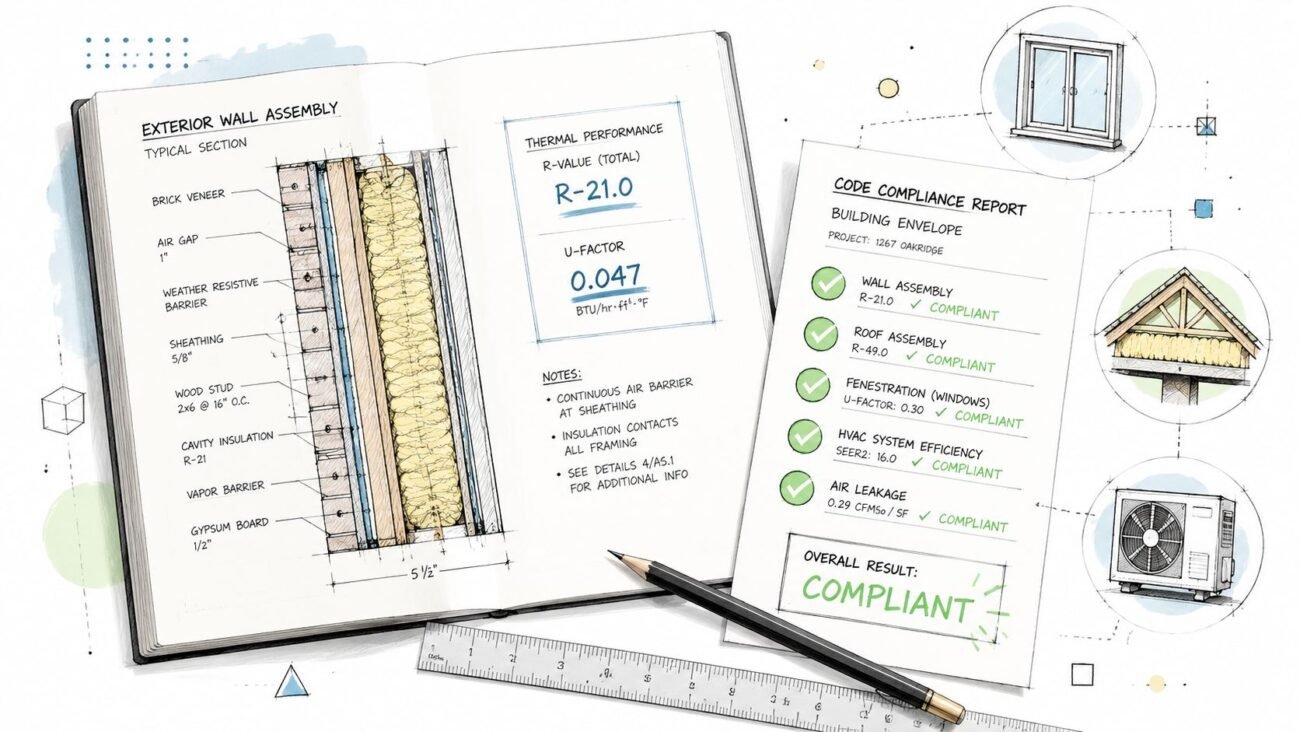
Material Specificity: Performance vs. Product
CDs specify materials based on performance and aesthetics (e.g., "architectural-grade maple plywood"). This sets a quality standard while allowing for competitive sourcing. Shop drawings must lock in the specifics: the exact manufacturer, product number, and finish code. It is a commitment from the fabricator on what they will purchase and install to meet the architect’s intent.
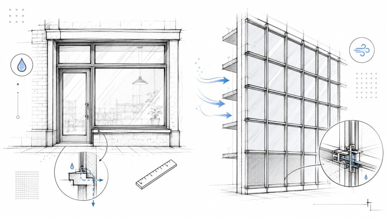
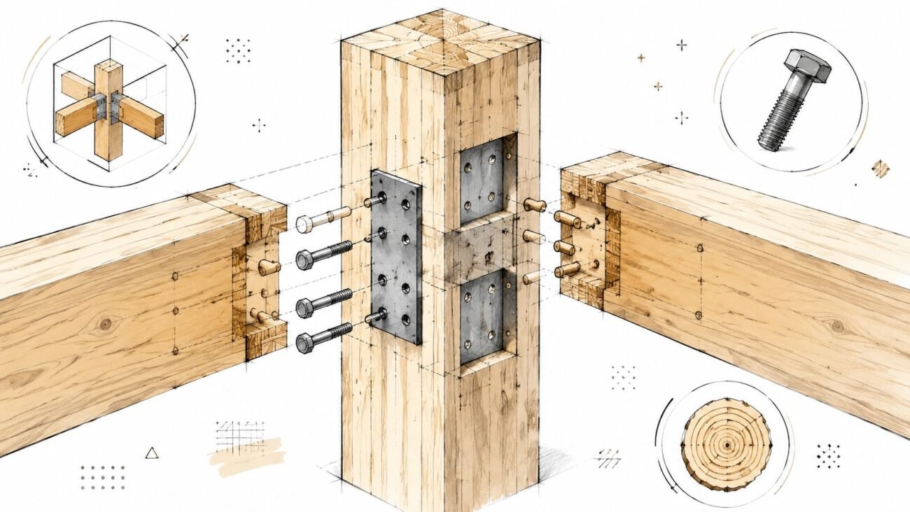
Connection Logic: Relationship vs. Assembly
This is arguably the most critical difference. Construction drawings show that components connect (a beam rests on a column). They almost never detail how. That responsibility falls to the fabricator’s engineering team.
Shop drawings must illustrate the precise connection logic—bolt patterns, weld types, plate thicknesses. This is where the fabricator’s expertise in means and methods is applied. They engineer the connection to meet specified loads while optimizing for their production system. This clear division of labor is the hallmark of a mature project team. To learn more about this relationship, see how builders should evaluate your construction drawings.
The Review Process: A Critical QA Checkpoint
The shop drawing submittal and review process isn't administrative overhead; it's one of the most important QA processes in a project. It’s a deliberate pause for stakeholders to confirm alignment before significant costs are incurred.
The purpose of the architect’s review is to confirm one thing: does the fabricator's plan conform to the design intent outlined in the construction drawings? It is not a check of the fabricator’s dimensions or means and methods. That responsibility remains with the trade partner.
The Submittal and Approval Workflow
A disciplined workflow ensures accountability. It moves from the creator of the detail to the coordinator and finally to the design team for validation.
- Creation: The fabricator produces shop drawings translating the design intent.
- GC Review: The general contractor reviews for coordination with other trades and schedule alignment.
- A/E Submission: The GC formally submits the drawings to the architect/engineer.
- A/E Review: The design team reviews strictly for conformance with their design intent.
- Action & Return: The drawings are returned with a clear status (e.g., Approved, Revise and Resubmit), signaling the next step.
This flow is designed to translate design intent into a buildable reality. A breakdown here leads directly to project friction.
This structured QA process catches discrepancies on paper, preventing them from becoming expensive, on-site problems. For a deeper look, you can review a detailed shop drawing example and its components.
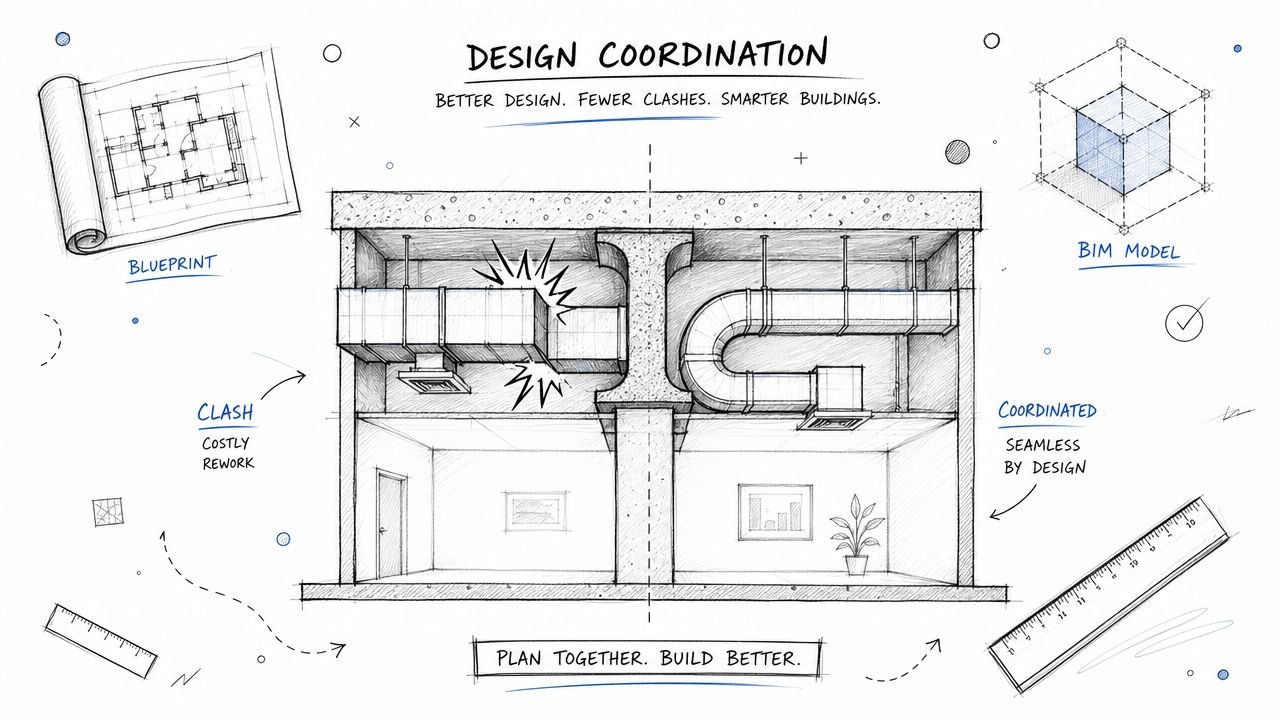
Aligning Drawings in Modern BIM Workflows
The classic divide between design intent and fabrication instructions is even more critical in a BIM environment. In a mature BIM workflow, the model is the single source of truth, feeding both construction documents and fabrication models. The handoff is no longer about exchanging PDFs; it’s about transferring intelligent model data.
Defining the Handoff with LOD
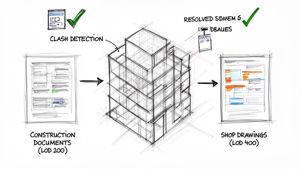
The best tool for managing this digital handoff is the Level of Development (LOD) specification, spelled out in the project’s BIM Execution Plan (BEP). This creates a clean, unambiguous checkpoint.
- Design Team (LOD 350): The architect and engineers develop their model to a level detailed enough for coordination and communicating design intent.
- Fabrication Team (LOD 400): Trade partners advance the model geometry and data to the level of detail required for actual fabrication and assembly.
When a fabricator receives an LOD 350 model, they know their job is to add the connection details, material specs, and tolerance data needed to build it. This discipline is the foundation of scalable, predictable project delivery. In an industry where major hubs handle a massive volume of the nation’s projects, as detailed by industry reports from sources like Vertical IQ, these coordinated workflows are essential. They allow scalable delivery pods to operate with the operational consistency and margin protection every firm needs. Being able to efficiently extract PDF data for seamless integration into BIM models is another key skill in this modern environment.
Conclusion: Intent Defines, Execution Delivers
The journey from blueprint to building is a relay race. The handoff between construction drawings and shop drawings is where the baton is passed—from design intent to production reality. One document defines the what; the other meticulously plans the how.
Getting this right is a hallmark of production maturity. It establishes clear lines of responsibility, turning the submittal process into a vital quality assurance checkpoint instead of a point of conflict. We’ve seen coordination cycles get shorter when teams agree on where one drawing set ends and the other begins.
Ultimately, mastering the difference between shop drawings and construction drawings in your workflow builds a system that removes ambiguity. It transforms the potential for friction into a structured, collaborative effort, ensuring that what is envisioned is precisely what gets built. That alignment is the real engine of flawless execution. To learn more about how this applies in practice, explore our guide on using shop drawings for construction.
At BIM Heroes, we believe reliable delivery is built on clear systems, not just more hours. If your team is looking to tighten the handoff from design to fabrication, a well-defined responsibility matrix is the ideal starting point. It’s a technical resource that drives clarity and predictability.