Spool drawings are the last mile of constructible information—the final, critical translation from a coordinated digital model to a buildable, real-world assembly. They turn complex BIM designs into manageable, installable packages for fabricators and field crews, bridging the gap between design intent and site execution.
The Last Mile From Digital Model to Physical Reality
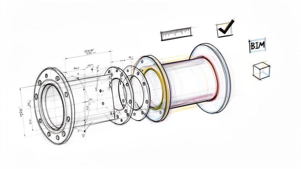
In the evolution from CAD to BIM, our industry mastered the art of creating perfectly coordinated, clash-free digital models. A detailed BIM model and its corresponding shop drawings prove that, in theory, every pipe, duct, and component fits.
But projects aren't built in theory. They're built on-site, and that's where even the best designs can fall apart.
Many field issues are not design errors; they are failures in how information was broken down for installation. Rework, schedule delays, and blown budgets often stem from a simple communication gap: the intelligence from the coordinated model never made it to the installers in an actionable format. This is precisely the gap that disciplined construction spooling exists to fill.
From Coordinated Intent to Installable Action
While shop drawings establish the coordinated intent for an entire system, a spool drawing translates that intent into a single, installable package. It is a hyper-specific set of instructions for one prefabricated assembly—a "spool"—that will be built in a controlled shop environment before it ever reaches the job site. This simple shift moves complex labor from the chaotic field to an efficient fabrication facility, protecting margins and ensuring quality.
A mature construction spooling strategy deconstructs a complex system by answering critical, real-world questions:
- Fabrication Limits: How large of a section can the fab shop realistically build, handle, and quality-check?
- Shipping & Logistics: Will this finished spool fit on a truck and through the building's access routes and lifts?
- Site Handling: Can the installation crew safely lift and maneuver this piece into its final position without specialized equipment?
- Installation Sequence: Does the fabrication order align with trade sequencing and the overall project schedule?
Without this level of detail, you're asking installers to improvise. They're left cutting components, guessing at connections, and wrestling with assemblies too heavy or awkward to install safely. That on-the-fly problem-solving kills productivity, compromises safety, and erodes project margins.
Effective spool drawings are not just about fabrication; they are about protecting project predictability. They systematically eliminate guesswork from the field, turning the digital certainty of a coordinated model into physical installation success.
Why Spool Quality is a Production Discipline
Creating effective fabrication spool drawings is less about drafting skill and more about production maturity. It demands a practical understanding of the entire BIM-to-installation workflow and recognizes that the quality of these final documents is a direct reflection of upstream discipline.
You can't get quality spools without a well-planned LOD strategy, rigorous BIM coordination, and a clear, accountable handoff from design to detailing.
When it all comes together, spool drawings become the vital link ensuring the value created during design actually makes it to the finish line. They are the final translation of coordinated design intent into installation-ready clarity—nothing more, nothing less.
Translating Coordinated Models Into Installable Packages
Creating spool drawings isn’t just digitally slicing up a BIM model. It’s about translating a clash-free design into a series of logical, installable packages that respect real-world constraints. Think of it this way: a full set of shop drawings is a map of the entire highway system. A spool drawing provides the precise, turn-by-turn directions for one critical leg of the journey.
This translation from a big-picture view to a micro, actionable instruction set is where you protect your margins. Every minute an installer spends on-site improvising, problem-solving, or waiting on an RFI is a direct hit to the bottom line. Good spooling answers those questions before they can stop work in its tracks.
The goal is to move complex assembly work from the unpredictable, high-cost field environment to a controlled, efficient fabrication shop. This shift is what drives operational consistency and predictable outcomes.
Bridging the Gap From Design to Site Logistics
A successful BIM to installation workflow lives or dies by how well the digital model reflects physical reality. The spooling process is the ultimate checkpoint for this, forcing a practical review of real-world constraints long before a single component is fabricated. It’s not just about what fits in the model; it’s about what can actually be built, shipped, and installed safely.
This is where you must address the gritty logistics:
- Fabrication Constraints: What is the maximum size or weight the fab shop can handle?
- Transportation Limits: Will the finished spool fit on a truck and be legal for transport?
- Site Access: Can the prefabricated component be maneuvered through the building, around other trades, and into place without a crane or demolition?
- Installation Sequencing: Are the spools tagged and prioritized to align with the construction schedule?
Ignoring these questions is a recipe for expensive on-site rework. A perfectly fabricated assembly is useless if it’s too large for the freight elevator or arrives before the area is ready for it.
A spool drawing is documented proof that someone has considered the entire lifecycle of an assembly—from digital file to fabrication bench, from delivery truck to final connection point. This foresight separates predictable projects from chaotic ones.
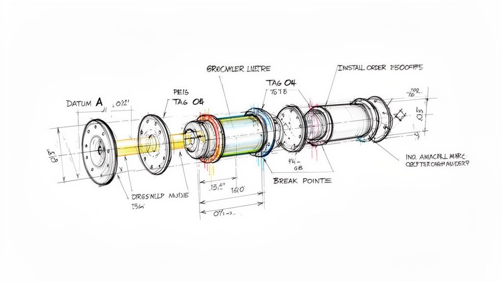
The graphic below shows how spool drawings act as the critical link between the digital model and the physical installation happening on-site.
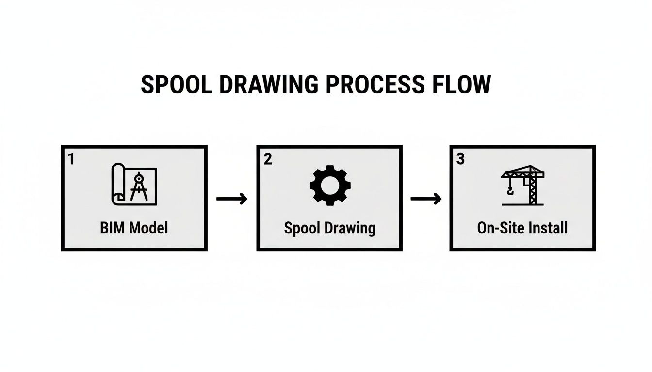
This visual drives home that spooling isn't an isolated task. It’s a vital conversion step that makes the intelligence baked into the BIM model accessible and actionable for the shop and field teams.
The Foundation for Prefabrication and Scalable Delivery
The discipline of construction spooling is what makes prefabrication a reliable and scalable strategy. Without clear, accurate, and logistically sound spool drawings, any attempt at off-site manufacturing becomes a high-risk gamble. The process ensures every component leaving the fab shop is built to precise specifications pulled directly from a fully coordinated model.
This systematic approach is essential for firms looking to scale up their delivery pods. Having consistent standards for creating fabrication spool drawings means teams can produce predictable, high-quality assemblies no matter the project. That reliability is built on a foundation of meticulous planning, which is detailed in our guide to the BIM clash detection and coordination process.
Ultimately, spool drawings are the mechanism that converts coordinated design intent into installation-ready clarity. They are the final checkpoint ensuring the digital precision achieved in the model translates directly to execution excellence in the field.
The Anatomy of a High-Quality Fabrication Spool Drawing
An effective fabrication spool drawing is a contract of clarity between the BIM model and the installation team. It contains just enough information to build and install a specific assembly—and absolutely nothing more. The quality of this document is a direct reflection of the upstream discipline in modeling, coordination, and QA processes.
When an installer has to stop and ask questions, the system has failed. High-quality spool drawings are designed to prevent those questions by focusing on a few non-negotiable, field-tested components that leave no room for misinterpretation. These elements are the building blocks of a predictable, efficient installation.
The DNA of an Installable Spool
The difference between a drawing that creates work and one that guides it comes down to the details. A truly useful spool drawing is surgically precise, providing exactly what the fabricator and installer need to execute their tasks without guesswork.
This level of precision is only possible when the underlying model has been developed with fabrication in mind. To learn more about how model accuracy impacts these outcomes, explore our guide on the Level of Detail (LOD) in BIM.
The core components of a high-quality spool include:
- Logical Breakpoints: Spools must be broken down based on real-world constraints, including fabrication capacity, shipping logistics, and on-site handling limits. A breakpoint that looks good in a model but results in an assembly too large for a freight elevator is a costly failure.
- Consistent Datums and Dimensions: Every measurement must originate from a clear, consistent reference point (a datum). Dimensions from face-of-flange to center-of-fitting eliminate any need for on-site calculation.
- Clear Connection Details: The drawing must explicitly show how the spool connects to adjacent spools or equipment, including weld types, bolt requirements, gasket specifications, and required clearances.
- Unique Tagging System: Each spool needs a unique identifier linking it to the fabrication schedule, bill of materials, and installation sequence plan. This tag follows the assembly from the shop floor to its final location.
A spool drawing's primary job is to remove decision-making from the field. Every dimension, tag, and connection detail should be an instruction, not a suggestion. This is the foundation of a scalable and predictable BIM to installation workflow.
Upstream Discipline Dictates Downstream Success
It’s a hard lesson learned in the field: you cannot create excellent fabrication spool drawings from a mediocre model. The quality of these final installation documents is a direct result of the rigor applied during the earlier phases of the project.
A poorly coordinated model, an ambiguous LOD plan, or a weak QA process will inevitably surface as errors and RFIs during fabrication and installation. In short, the spool drawing is the final report card on your entire production maturity.
A Checklist for Installation-Ready Spools
To ensure every spool drawing is ready for the real world, it must pass a critical test. Just like any other engineering output, a high-quality fabrication spool drawing benefits from clear and precise specifications. You can learn how to write technical requirements that translate directly into effective fabrication documents.
Here's a breakdown of the key elements that distinguish an installation-ready document from a simple detail.
Key Elements of an Effective Spool Drawing
| Component | Description | Why It Prevents Field Issues |
|---|---|---|
| Isometric View | A clear, 3D representation of the spool assembly, often with exploded views of complex connections. | Provides immediate visual context, reducing the chance of misinterpreting 2D plans and assembling components incorrectly. |
| Bill of Materials (BOM) | A complete list of every pipe, fitting, flange, and component required for that specific spool. | Ensures the fab shop orders and uses the correct materials, preventing shortages or substitutions that cause delays and RFIs. |
| Cut Lists | Precise cut lengths for all linear components like pipes. | Eliminates manual measurement and calculation in the shop, ensuring accuracy and reducing material waste. |
| Weld Map & Details | A diagram showing the location, type, and numbering of every shop and field weld. | Provides clear instructions for welders and quality control inspectors, ensuring compliance with project specifications and codes. |
The anatomy of a great spool drawing is simple. It's a document born from a disciplined process, designed with empathy for the fabricator and installer, and relentlessly focused on providing clarity.
How Smart Spooling Prevents Common Field Issues
Every seasoned BIM manager and installer knows the feeling: a project looks perfect in the model, only to descend into chaos on site. The most expensive problems in construction—rework, schedule delays, and safety incidents—rarely come from a single design flaw. They are born from a series of small but costly field improvisations.
This is where smart construction spooling becomes your best risk mitigation tool. Well-prepared spool drawings aren't just for fabrication; they are a direct countermeasure to the most common issues that plague installation. They systematically remove the need for on-site decision-making, which is often done under pressure and with incomplete information.
A failure in spooling isn't a documentation error; it's a failure to plan for physical reality. The consequences show up as installers scratching their heads, cutting perfectly good material, and sending RFIs that bring work to a screeching halt.
Eliminating On-Site Improvisation
Picture this: an installer receives a bundle of pipes and a general arrangement drawing. The drawing shows where the system goes, but not how it should be assembled. Now they are left to figure out connections, measure and cut pipe on a scissor lift, and hope it aligns with the next trade's work.
Effective spool drawings stop this cold by delivering pre-assembled, quality-controlled sections with crystal-clear instructions.
- No Guesswork: Every cut length, fitting orientation, and connection point is predefined from the coordinated model.
- Reduced Field Labor: Assembly moves from the job site to a controlled shop where work is safer, faster, and more accurate.
- Fewer RFIs: Questions about assembly are answered before material leaves the shop, preventing costly work stoppages.
This disciplined BIM to installation workflow turns installers into assemblers, allowing them to focus on their core task efficiently and safely.
Solving Logistical Nightmares Before They Happen
Another classic field issue is logistics. A massive, prefabricated rack arrives on site, perfectly built, only for the crew to discover it’s too wide for the service elevator or too heavy for the available lifting equipment. The result? A costly effort to break down the assembly in the field—the very work prefabrication was meant to avoid.
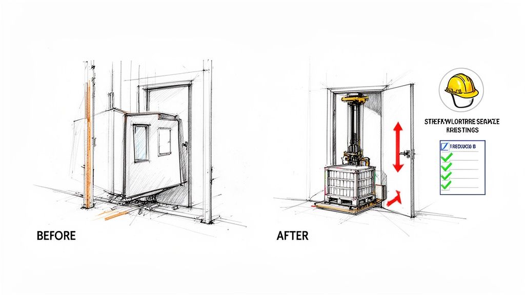
Smart spooling forces these logistical conversations to happen early. Detailers must define spool breaks based not just on the model, but on real-world constraints.
The most important questions answered by a spool drawing are often about logistics: Will it fit on the truck? Can we get it through the door? Can the crew lift it safely? Answering "no" in the digital phase saves thousands in the field.
This process involves defining weight limits, dimensional envelopes for transport, and lift plans. By embedding these constraints into the fabrication spool drawings, the entire production chain—from shop floor to installation point—is aligned with an executable plan. The focus shifts from "Can we build it?" to "Can we install it?"
Improving Safety and Predictability
Ultimately, the biggest win from a disciplined spooling process is predictability. When spools arrive on-site, they fit. They connect as planned. The installation sequence is clear. This operational consistency has a direct and powerful impact on safety.
Fewer improvised lifts, less on-site cutting and welding, and a more organized work area all contribute to a safer project. By planning the work in painstaking detail, spool drawings help remove the unexpected variables that so often lead to incidents. This system-driven approach protects not only your margins but also your people.
Mastering the BIM-to-Spool Handoff Process
A high-quality spool drawing is the direct result of a disciplined production process. The single most critical—and often overlooked—decision checkpoint in the entire BIM to installation workflow is the formal handoff from the BIM coordination team to the detailers. This is where potential field issues are either prevented or permanently baked into the project.
Without a structured handoff, teams risk creating spools from an unapproved model, leading to fabrication errors that don't show up until materials are on site. It’s a classic case of “garbage in, garbage out.” A sloppy handoff guarantees downstream pain in the form of RFIs, rework, and budget overruns.
This transition must be treated as a formal gate in the production timeline—a moment to verify that the model is truly ready for fabrication detailing.
Establishing a Clear Handoff Protocol
The handoff isn’t a casual email with a model attached; it’s a procedural checkpoint. Its purpose is to ensure the detailer receives a locked, signed-off model that reflects every coordinated decision. This prevents the common scenario where a detailer starts working, only for the coordination team to make a change that instantly invalidates their work.
A mature handoff process includes a few key elements:
- A Signed-Off Model: The areas of the model designated for spooling must be formally approved by all stakeholders and locked to prevent further changes.
- Defined LOD: The model must meet the required Level of Detail (LOD 400) for fabrication, containing accurate geometry, materials, and connection information.
- Established Standards: All parties must agree on annotation styles, dimensioning standards, and the spool tagging convention before work begins.
This protocol protects project margins by creating clear accountability and ensuring detailers work from a reliable single source of truth.
Key Information for the Handoff Package
To set the spooling team up for success, the handoff needs to be more than just the model file. It should be a complete package of instructions that gives the detailer essential context.
The goal of the handoff is to transfer not just data, but intent. The detailer needs to understand the logistical and sequencing constraints that dictate how the model is broken down into installable spools.
This package should clearly define:
- Spool Break Locations: Preliminary breakpoints agreed upon by the project team, respecting shipping and handling limits.
- Installation Sequence: A high-level plan for the installation order, which allows spool tags to be assigned logically.
- Site Logistics Constraints: Documented limits on weight, dimensions for site access (doors, lifts), and material handling capabilities.
The rise of pipe spool drawings has transformed industrial construction by enabling prefabrication, which can reduce on-site labor hours significantly. You can discover insights from Tejjy Inc. on piping spool drawings to see how 3D isometric views are changing MEP systems. This makes the handoff process even more vital, as those efficiencies hinge on accurate upfront information.
By mastering this handoff, teams shift from a reactive workflow to a proactive, manufacturing-style approach. This discipline is the foundation for creating reliable fabrication spool drawings that make prefabrication predictable and profitable. To better understand how these documents fit into the bigger picture, check out our detailed guide on shop drawings.
Your Path to Installation-Ready Clarity
Most problems in the field aren’t design mistakes; they're information gaps. The most expensive issues—rework, schedule blowouts, and safety incidents—usually trace back to a simple failure: not translating the coordinated design into clear, buildable instructions for the installation crew.
This is exactly where a disciplined construction spooling process pays for itself. Spool drawings are the critical link that turns a validated BIM model into a set of precise packages for the fab shop and the field. When done right, they take the guesswork out of installation, protecting your margins and ensuring all the hard work done in coordination makes it to the finish line.
From Digital Intent to Physical Certainty
Ultimately, the quality of your fabrication spool drawings reflects your team’s production maturity. It shows you understand that operational consistency is built on solid decision checkpoints, clear communication, and a respect for the realities of site logistics.
The spooling process forces everyone to think beyond the digital model. It makes you consider the entire journey of an assembly—from how it’s built in the shop and shipped to the site, to how it’s handled and finally bolted into place.
The purpose of spool drawings is to deliver installation-ready clarity. They succeed when they give fabricators and installers just enough information to do their jobs perfectly, without ever needing to stop and ask a question.
This commitment to clarity separates predictable, profitable projects from chaotic ones. It’s how the best firms deliver on time and build a reputation for reliability. The focus shifts from just creating drawings to building a repeatable system that delivers predictable results.
Ready to close the gap between your coordinated models and what happens in the field? It starts with a rock-solid handoff.
Download our BIM-to-Spool Handoff Framework for a practical checklist that ensures your detailing team has everything they need to create installation-ready spool drawings from day one.
A Few Common Questions About Spool Drawings
Even after understanding their purpose, spool drawings can raise practical questions for architects, BIM managers, and trade partners. Let's tackle a few of the most common ones.
What Is the Difference Between Shop Drawings and Spool Drawings?
Think of it this way: a shop drawing is the master plan for an entire system, like a complete plumbing riser. It shows how all parts fit together inside the building, focusing on high-level coordination and system-wide intent.
A spool drawing is the step-by-step instruction manual for a single, prefabricated piece of that system. It breaks the larger assembly into buildable sections ("spools") and gives the fabrication shop the exact dimensions, materials, and connection details to build it. It then tells the field crew precisely how to install that piece.
In short, shop drawings are for coordination; spool drawings are for production.
What LOD Is Required Before Creating Spool Drawings?
To create reliable fabrication spool drawings, the BIM model must be at LOD 400. At this level, every element is modeled with the specific details needed for fabrication and assembly—precise geometry, connection types, and material specs.
Trying to generate spools from a lower LOD model, like LOD 300 (which only shows general design intent), is a primary cause of field errors. The model simply lacks the fabrication-specific data required to build something that fits perfectly. Discipline in the BIM-to-installation workflow is what separates successful prefabrication from a costly mess.
A spool drawing is only as reliable as the model it comes from. Starting with anything less than a fully detailed and approved LOD 400 model is a direct path to rework and margin erosion.
Who Is Responsible for Creating Spool Drawings?
This responsibility almost always falls to the trade contractor—mechanical, electrical, or plumbing—or their specialized detailing partner. The design team establishes the vision, but the trade contractor owns the means and methods of getting it built and installed.
They start by creating shop drawings for coordination. Once those are signed off, they use that coordinated model to generate the spool drawings that guide their fab shop and field installers, ensuring the spools perfectly match the final, agreed-upon construction plan.
Can Spooling Be Done Without a BIM Model?
Technically, yes, spool drawings could be created from 2D plans. However, it’s a manual, slow, and incredibly error-prone process that modern construction has moved away from for good reason. Today’s projects rely on a coordinated 3D BIM model as the single source of truth.
When you generate spools directly from a validated BIM, you know every component is clash-free, dimensionally accurate, and aligned with other trades. That certainty is impossible to achieve with a 2D workflow. Using BIM as the foundation is what gives prefabrication its power and predictability.
At BIM Heroes, we believe that predictable outcomes are the result of disciplined processes. We help firms implement the systems needed to turn coordinated models into installation-ready clarity, protecting project margins and building a reputation for reliable delivery.
Find out how we can support your production workflows at https://www.bimheroes.com.