Meta description: A practical guide to hot and cold water routing in tight building layouts, with early coordination strategies for risers, pipe sizing, plenums, insulation, and BIM-based MEP planning.
A lot of domestic water problems don't start with bad plumbing design. They start with late plumbing design.
The familiar version goes like this. A multifamily or mixed-use job reaches design development. HVAC has already taken the cleanest corridor in the ceiling. Structure has left shallow clear zones between beam bottoms and finished ceiling. The riser locations that looked fine in schematic design do not line up with the fixture clusters on the typical floor. Then the plumbing team starts serious routing and realizes the system doesn't fit the building the way the building is now organized.
That isn't a drafting issue. It's a sequencing issue.
In tight projects, hot and cold water routing needs to be treated as an early coordination problem. If risers, main elevations, branch logic, and insulation envelope aren't resolved before the plenum gets consumed by larger systems, the plumbing model becomes a workaround exercise. That's where margins disappear, RFIs multiply, and production teams end up redrawing the same floor three times.
The Cost of Late Plumbing Coordination
Late plumbing coordination always looks expensive in the same way. The first pass seems manageable. The second pass starts adding offsets, dropped bulkheads, shifted shaft walls, and fixture branch reroutes. By the third pass, the team isn't optimizing anymore. They're preserving what they can.
The cost isn't only the rerouting effort. It's the chain reaction that follows. A riser shift changes branch lengths. Branch lengths change pipe sizing. Pipe sizing changes insulation envelope and access clearances. Then the reflected ceiling plan, framing coordination, and penetration package all need another review.
Field lesson: If domestic water routing begins after HVAC mains are already fixed in a tight plenum, plumbing rarely gets its preferred path. It gets the leftover geometry.
That's why experienced teams push MEP plumbing coordination upstream. The point isn't to fully detail every domestic water line in schematic design. The point is to lock the decisions that control whether routing will remain simple later.
The Unspoken Coordination Hierarchy
Every project team knows there's a coordination hierarchy, even if nobody writes it into the kickoff agenda. Space gets claimed in a predictable order.
Structure defines the hard boundary first. HVAC usually takes the largest continuous runs next because ductwork needs width, depth, and long clean paths. Fire protection typically follows with its own elevation and coverage constraints. Plumbing then enters a plenum that is already partially spoken for. Electrical and low voltage usually have the most routing flexibility.
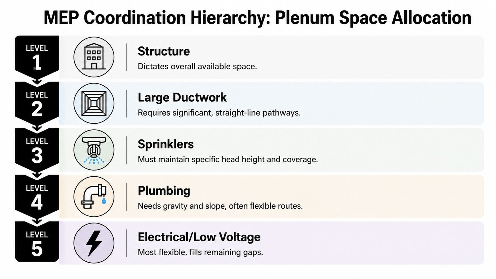
What the plenum stack really means
In a constrained ceiling zone, the stack often reads like this from top to bottom:
- Structural slab or deck: the immovable limit
- Beams, joists, or transfer elements: the geometry that breaks continuous routing
- Primary duct mains: the system that usually claims the best corridor
- Sprinkler mains: coordinated around head elevation and coverage
- Domestic water mains: often forced into fragmented space
- Secondary duct branches and terminal connections: small individually, disruptive in aggregate
- Conduit and low voltage: flexible, but still competing for space
- Finished ceiling: the line that exposes every coordination mistake
The practical issue isn't that plumbing comes later by rule. It's that plumbing pays the price when nobody reserves space for it early.
Why plumbing needs an earlier seat
Domestic water doesn't need the largest corridors, but it does need predictable corridors. Hot water supply, cold water supply, recirculation return when used, insulation thickness, valve access, and branch turns all need room that won't disappear after the first duct pass.
If your team is still treating plumbing as “small pipe that can find a way,” the model will eventually prove otherwise.
Plumbing gets flexible routes, not unlimited routes.
On high-density projects, the right move is simple. Allocate a plumbing elevation zone before the plenum is effectively gone. That decision prevents a lot of downstream clash-fixing that never should have existed.
Riser Placement The Decision That Defines the System
If I had to identify the single decision that most often determines whether domestic water routing stays efficient, it's riser placement. Get that wrong and the rest of the system turns into damage control.
A riser is not just a vertical pipe location. It sets the logic for horizontal main distribution, branch run length, shaft size, coordination burden, and often the number of routing compromises the team will accept later.
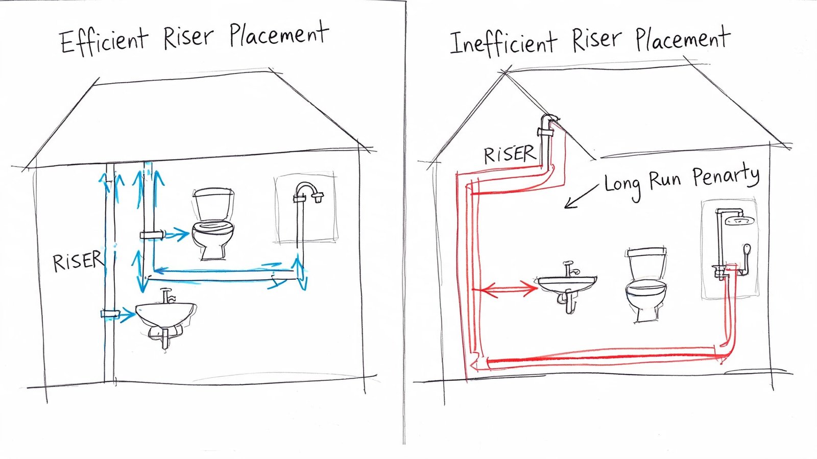
Two failure modes show up again and again
The first is the riser that sits too far from the densest fixture cluster. On paper, the floor still works. In the model, it creates long horizontal runs, bigger mains than the team expected, and more congestion exactly where the plenum is already tight.
The second is the riser placed with no structural validation. That's where a seemingly clean stack line collides with post-tensioning restrictions, beam framing, or a shaft geometry that can't support the pipes, insulation, valves, and access the system needs.
What should drive riser placement
A disciplined riser decision usually comes from four checks done early:
- Fixture cluster proximity: In multifamily work, that usually means staying close to bathrooms and kitchens that repeat on the typical floor. In commercial work, it often means toilet room cores and pantry zones.
- Structural penetration feasibility: A riser that works architecturally but fails structurally isn't a valid option.
- Shaft and chase capacity: Hot, cold, recirc, waste, vent, insulation, supports, and access need a real envelope, not an optimistic one.
- Pressure zone logic: In taller buildings, risers also have to align with the domestic water pressure strategy.
The production checkpoint that matters
Riser placement should be treated like a decision gate, not a placeholder. Before the location is considered fixed, the plumbing lead, structural engineer, architect, and BIM coordinator should all confirm that the line works through the building vertically and supports an efficient branch strategy horizontally.
Coordination rule: Don't approve riser locations because they look centered on plan. Approve them because they survive structure, shaft sizing, and typical-floor branch routing.
That's the difference between a riser that defines the system cleanly and one that keeps generating rework.
Choosing a Hot Water Distribution Strategy
Hot water strategy changes the routing problem immediately. It affects pipe count, chase width, valve requirements, and what other trades need to accommodate.
Too many teams choose the hot water system for performance reasons alone, then discover that the routing burden wasn't priced into the coordination effort. In tight layouts, that's a mistake.
Central recirculation versus simpler layouts
A central recirculation layout gives reliable hot water delivery and is often the right answer in larger buildings. It also means the building carries both supply and return through the distribution path. Every chase and corridor segment now has to support that extra pipe, plus balancing devices and access where needed. The routing is more stable operationally, but it takes more discipline spatially.
A trunk-and-branch without recirculation is lighter from a routing standpoint. Fewer pipes. Less chase demand. Less coordination pressure. But when branch distances stretch, the operational trade-off shows up quickly in user experience and water waste. This strategy works best where runs stay short and the floor plan supports that simplicity.
Point-of-use and heat trace options
Point-of-use heaters can remove a lot of distribution complexity. In some layouts, reducing long hot water runs solves the hardest part of the plumbing model. But that benefit shifts load and coordination into other systems. Electrical service, equipment space, maintenance access, and architectural integration become more prominent.
Heat trace on insulated supply mains can reduce the need for a dedicated return path in some applications. That cuts pipe count, but it introduces electrical coordination and raises the importance of insulation continuity and access planning.
Material choice changes the route too
Material choice also matters. PEX has a thermal conductivity of 0.4 W/m·K compared to 50 W/m·K for copper, which helps minimize standby heat loss, but its thermal expansion of 0.025-0.030 mm/m·K means expansion loops are needed every 9-12 meters according to the Wavin technical handbook on hot and cold water systems.
That trade-off matters in BIM. Lower heat loss is useful. Expansion allowances still need real space. If the modeler treats flexible plastic piping as “easy to route” without accounting for movement, supports, and expansion geometry, the coordination model becomes misleading.
A good hot water strategy doesn't just perform hydraulically. It fits the building without creating a hidden coordination tax.
How Pipe Sizing Impacts Routing Flexibility
Pipe sizing is where hydraulic intent becomes physical reality. A main that works on a calculation sheet may still fail in production if its coordinated envelope doesn't fit the plenum the team has.
That's why sizing decisions should never be isolated from routing decisions. In domestic water system design, diameter determines whether a main can stay in one corridor, whether it has to drop below another system, and whether branch takeoffs remain clean or become a series of offsets.
Velocity limits aren't just hydraulic guidance
Velocity limits also shape the route. Maximum recommended flow velocity is 2.0 m/s for accessible cold water pipes at 10°C and 1.3 m/s for accessible hot water pipes at 90°C. Exceeding those thresholds can increase noise by 10-20 dB and reduce pipe lifespan by 30-50%, as noted in the CIBSE hot and cold water design guidance.
That matters because teams sometimes try to preserve space by pushing pipe sizes down too aggressively. In tight buildings, that can backfire. You may gain a little room in the model and create a long-term noise and wear problem in the field.
Model the real envelope
The practical rule is straightforward. Coordinate the outside insulated envelope, not the nominal pipe.
That's where many coordination models fail. Pipes clear in clash detection because the model only shows carrier size. Then insulation is added later and the “resolved” corridor is no longer resolved. Good plumbing design workflows treat insulation, access, support spacing, and valve clearance as part of the route from the beginning.
A compact system is not the same thing as an undersized system. Routing flexibility comes from correct sizing, not optimistic sizing.
Horizontal Routing Tactics for Constrained Plenums
When the plenum is tight, default routing habits stop working. In such situations, teams need tactics, not assumptions.
The first tactic is to stop chasing a perfect straight run if the building won't support one. The better objective is a route that is buildable, repeatable, and coordinated early enough that other systems can respond to it.
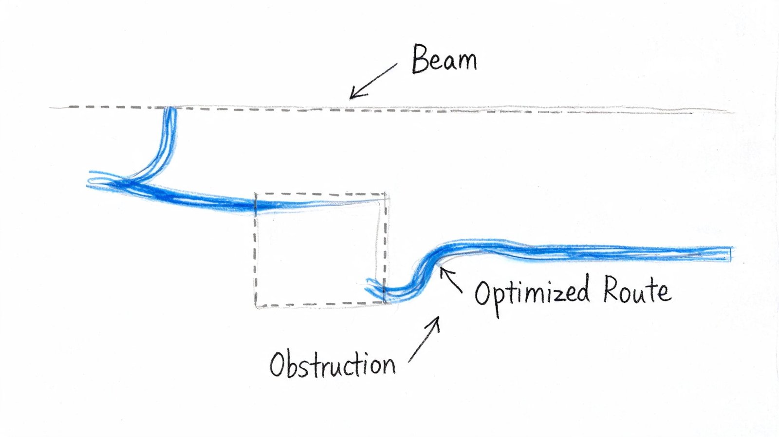
Tactics that usually work
- Route parallel to framing where possible: If beams run one direction, keep mains parallel to that span when it supports the fixture strategy. It avoids unnecessary structural crossings.
- Schedule beam penetrations, don't assume them: When crossing is unavoidable, get the structural engineer involved early. Penetration location, size, and spacing need to be agreed before the route is considered real.
- Use slab voids when the structure allows it: Ribbed or waffle systems can create opportunities for smaller lines if the structural rules support that approach.
- Consolidate into dedicated chases: A compact chase can reduce ceiling congestion if the floor plan can absorb it.
- Distribute by zone from the riser: Shorter horizontal mains usually mean smaller coordinated envelopes and fewer conflict points.
The route should match the building type
In some commercial layouts, raised access flooring can become the better distribution zone. In some residential towers, dedicated stacked chases outperform broad corridor distribution because they preserve a cleaner ceiling for other trades. In some mixed-use podiums, the answer changes from level to level because retail and residential don't consume space the same way.
That's why rigid standards fail here. The route has to respond to structure, program, and vertical alignment together.
A good route is one the field team can understand at a glance and the coordination team doesn't have to defend every week.
For teams dealing with chronic congestion above the ceiling, it also helps to review how the full plenum is being allocated, not just where the pipes are being drawn. That's where plenum coordination strategy becomes less about clash screenshots and more about system ownership of space.
Managing Hot and Cold Water Separation
Thermal separation gets ignored until the model is already crowded. Then someone notices the cold water line is traveling beside or below hot water long enough to create a performance problem.
Hot and cold water systems need separation because unwanted heat transfer affects both lines. Cold water gains heat. Hot water loses useful temperature. In tighter conditions, that's not just an efficiency issue. It can also affect risk management where water temperature control matters.
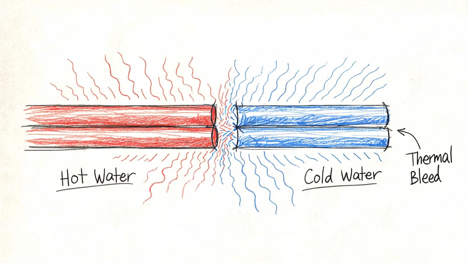
What to do when space is limited
If the building allows physical separation, take it. It's the cleanest answer.
If the space doesn't allow it, treat insulation on both lines as part of the thermal control strategy. Insulating only the hot side often isn't enough in a dense routing condition. The cold line still needs protection from heat gain.
Model the thermal decision, don't leave it implied
This is one of those details that has to appear in the BIM model exactly as intended. Pipe order matters. Vertical stacking matters. A cold line placed directly below an unprotected hot line creates a predictable problem. Once that arrangement is coordinated into the ceiling, it tends to stay there.
Keep thermal separation visible in the model. If it only exists in notes, the field usually inherits the compromise.
The fix is usually simple when addressed early and annoying when discovered late.
Common Planning Failures and How to Avoid Them
Most routing failures in tight buildings are process failures wearing a plumbing label. The technical issues are real, but they usually originate in decision timing.
The anti-patterns worth watching
- Risers fixed before structure is validated: The riser “works” until slab restrictions, beam framing, or shaft geometry force a relocation.
- Domestic water assigned the same elevation band as major ducts: That sets up repeated conflict instead of a coordinated vertical stack.
- Insulation omitted from the model: Clearance appears acceptable in coordination and disappears in installation.
- Beam penetrations treated as automatic: Structural review arrives late and the horizontal route collapses.
- Branch strategy left unresolved too long: Main routing gets developed before fixture distribution logic is stable.
What mature teams do differently
They add decision checkpoints. They reserve routing zones early. They validate risers against real structure. They model the actual pipe envelope. They also know that clash detection is only one piece of the job. A system can be “clash-free” and still be poor production.
That's why coordinated deliverables such as plumbing shop drawings matter. They force the team to answer the buildability questions that schematic placeholders tend to hide.
The big takeaway is simple. If the project waits until design development to think seriously about plumbing routing tight buildings, the team is already negotiating from a weaker position.
Conclusion The Case for Early Routing Strategy
The hardest domestic water problems in dense buildings are usually predictable well before the first serious clash meeting. The warning signs show up early. Tight floor-to-floor height. Long fixture distribution. Shared shafts. Structural depth that leaves little forgiveness. HVAC mains that need the same corridor plumbing was assuming.
That's why hot and cold water routing belongs in schematic design strategy, not as a late production cleanup task. Riser location, distribution type, pressure logic, pipe sizing direction, insulation allowance, and elevation zones all need early agreement if the system is going to remain efficient.
Late changes cost more because they touch more people and more drawings. Early decisions cost less because they prevent the redraw.
If you're looking at a project and already seeing shallow plenums, misaligned fixture groups, or uncertain riser paths, that's the right moment to resolve routing logic. Not after the ceiling is already full.
If you're dealing with a building where hot and cold water systems are already looking constrained in early design, BIM Heroes can help with the production side of the problem. Their team supports MEP coordination, riser planning against structural limits, plumbing BIM workflows, and the kind of routing discipline that prevents avoidable RFIs later. If useful, reach out for a checklist, template, or an early-stage review framework before the layout gets harder to change.