Meta description: Practical guide to parapet details in commercial CD sets. Learn how to document coping, flashing, transitions, fire coordination, and Revit standards to reduce RFIs and improve constructability.
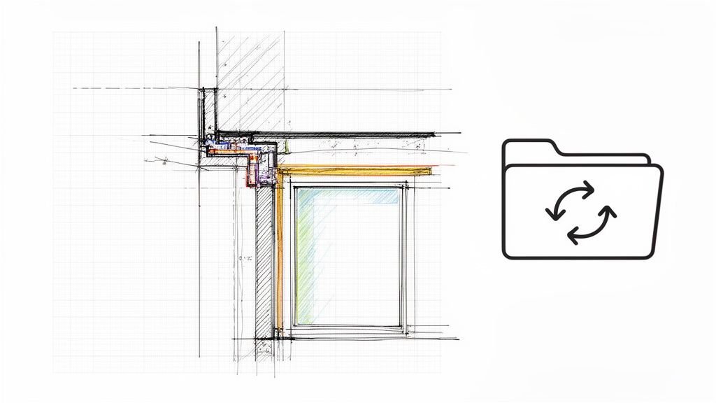
The roof plan shows a parapet. The exterior elevation shows a clean roof edge. Then the field team opens the detail sheets and finds almost nothing about how that parapet is supposed to go together.
That's where avoidable RFIs start. The roofer decides how high to turn the membrane. The sheet metal fabricator guesses the coping attachment. The mason or framer builds the wall, but nobody can point to one coordinated section that shows where the air barrier, WRB, flashing, insulation, and cap all meet. Once that happens, the job is running on interpretation instead of documentation.
Good parapet details close that gap. They turn a roof edge from a drawing symbol into a buildable assembly. In a commercial CD set, that means more than one enlarged section. It means coordinated details, clear references, disciplined notation, and enough information that the contractor doesn't have to invent the assembly in the field.
Introduction
A missing parapet detail rarely looks urgent in the office. On paper, the wall extends above the roof, the elevation reads correctly, and the roof plan seems complete. In the field, that same omission creates a chain reaction.
The contractor still has to build it. Someone has to decide how the roofing membrane terminates, how the coping gets anchored, how the top of wall stays dry during sequencing, and how the wall assembly changes once both faces are exposed. If the drawings don't answer those questions, the answers come back as RFIs, substitution requests, or improvised field conditions.
The problem isn't that parapets are obscure. The problem is that they sit at the intersection of multiple systems, and most sheet sets document them too loosely. That's why they fail so often in both documentation and performance.
Britannica's history of the parapet is a useful reminder that this edge condition has always been about protection first, even as its role expanded into enclosure performance, equipment screening, and safety.
The Anatomy of a Bulletproof Parapet Detail
A bulletproof parapet detail gives the field enough information to price it, sequence it, and build it without inventing the missing parts. If the roofer, framer, sheet metal subcontractor, and waterproofing installer can each read the same detail and reach different conclusions, the sheet set is still carrying risk.
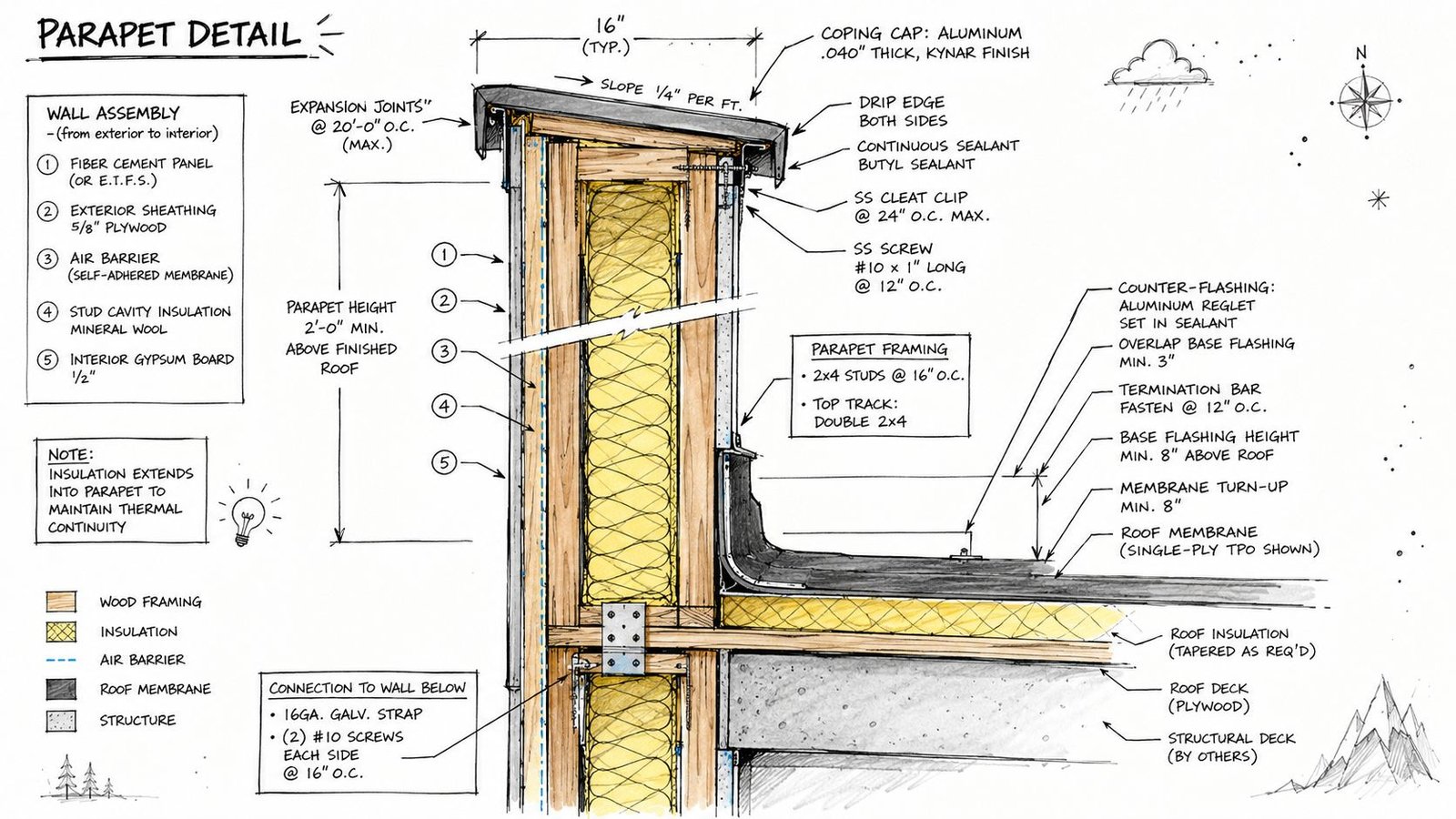
Start with the dimensions that control everything
Put the controlling dimensions in the enlarged detail, not only in a building section. The one that drives nearly every downstream decision is parapet height from the finished roof surface to the top of coping. If that dimension is missing at the point of use, submittals stall, installers build to assumptions, and plan reviewers start marking up related sheets to find confirmation.
Show the wall width, coping width, overhang, membrane turn-up zone, and any vertical offsets that affect attachment or backing. If the project has a code-driven minimum parapet height for a specific condition, call out the requirement directly in the detail and in the applicable code notes. Do not rely on someone in the field to connect that requirement from another sheet.
Show the parapet as wall continuation, not a generic roof edge
A parapet is the wall assembly continuing above the roof line, with a different exposure profile and a tighter concentration of trades. That distinction matters because the detail has to carry the wall logic through the roof transition without losing material continuity or attachment logic.
At minimum, the detail should identify:
- Wall type continuation at the parapet, including framing, masonry, or stud backup
- Interior and exterior finish conditions where exposure changes on one or both faces
- Sheathing and substrate locations on each side of the assembly
- Air, water, vapor, and thermal control layers with clear continuity through the transition
- Blocking, nailers, and backing required for membrane termination and coping attachment
- Top-of-wall protection during construction if the wall can be exposed before the coping is installed
Many drawing sets exhibit vagueness in this regard. The wall section may show the WRB. The roof detail may show the membrane. The parapet enlargement then turns into a graphic compromise that never clearly shows how those systems meet. RFIs frequently stem from that gap.
Siplast's parapet continuity guidance is useful because it treats the parapet as a control-layer transition, not just a metal cap condition.
Field rule: If one subcontractor has to stop and ask where their work terminates because the adjacent trade is not shown, the detail is incomplete.
Draw the interfaces that usually get delegated by mistake
Good parapet details do more than identify materials. They define responsibility at the interfaces.
Draw the membrane termination. Draw the substrate it fastens to. Draw the blocking that makes the fastening possible. Draw the coping support condition and the fastening concept. If the coping manufacturer is expected to engineer part of the assembly, show the design intent clearly enough that the delegated submittal cannot drift away from the wall and roof assemblies already in the CDs.
The same discipline applies to simple-looking conditions. A note such as “metal coping by others” leaves too much open. It does not tell the estimator what backing is required, it does not tell the installer where the membrane stops, and it does not tell the architect what dimensional tolerances the assembly can absorb.
A reliable parapet detail reduces decision-making in the field. That is how it protects schedule and fee.
Mastering Parapet Waterproofing and Flashing
Most roof-edge failures don't come from one bad material. They come from a broken sequence. The parapet is where sequencing matters most because water management, air sealing, and terminations all get compressed into a tight zone.
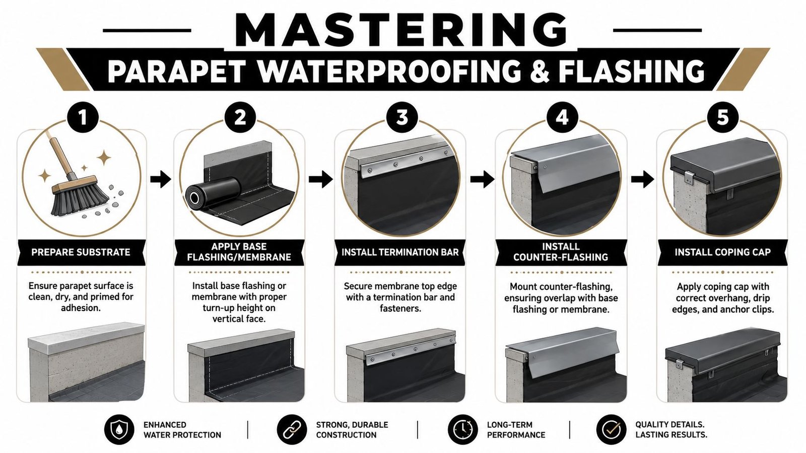
Draw the waterproofing in install order
If you want fewer RFIs, detail the assembly in the same order the field will build it. That usually means substrate, membrane turn-up, termination, counter-flashing, then coping.
Building Science Corporation has a nickname for chronic parapet failure: “parapetitus.” It uses that term because parapets interrupt the water, air, thermal, and vapor control layers and are exposed on three sides, making them one of the most failure-prone details in construction, as explained in BSI-050 Parapets Where Roofs Meet Walls.
That's why a generic note like “flash per manufacturer” won't carry a commercial CD set very far.
What your flashing detail needs to show
The detail should answer these questions without sending the reader to three other sheets:
- Base flashing height above the roof plane
- Membrane substrate on the vertical face
- Termination method such as bar, reglet, or other defined condition
- Counter-flashing overlap with the base flashing
- Top-of-wall seal below the cap
- Drainage path if masonry can absorb and release water
For masonry wall conditions, through-wall flashing at the base of the parapet needs to be shown with slope to exterior and weep strategy clearly indicated. If it's omitted, the drawing is incomplete.
Waterproofing doesn't stop at the roofing scope
Parapet failures often show up in projects with vented façades and rainscreen systems because teams coordinate the wall well, then under-document the roof-to-wall interface. That interface needs the same discipline you'd apply to a rainscreen cladding system. Different trade package, same coordination problem.
The best parapet flashing detail is the one that leaves no room for field invention.
A practical production move is to add one enlarged section for the typical vertical sequence and one companion detail for the top-of-wall closure. That split makes review faster and catches omissions earlier.
Detailing the Coping Cap System
The coping cap is where many drawing sets get lazy. It's shown as a thin metal line at the top of the parapet, then everyone acts surprised when submittals come back with unanswered questions.
What the coping must do
The coping has one job on paper and several jobs in the field. It has to shed water, protect the top of wall, accommodate movement, and stay attached under service conditions. If the detail only addresses appearance, the assembly is underdescribed.
At minimum, show these attributes:
- Width and overhang on both faces
- Drip edges so water breaks cleanly
- Slope direction shown graphically in the section
- Joint treatment with lap, cover plate, or sealant strategy as appropriate
- Anchorage using clips or cleats, not sealant as the primary restraint
What usually goes wrong
Three failures show up repeatedly in reviews. First, the coping is drawn flat with no slope direction. Second, the joints are noted but not described. Third, anchorage is delegated to deferred submittals without enough basis in the CDs to verify compatibility with the wall assembly below.
A good parapet coping detail construction documents package gives the sheet metal fabricator something usable and gives the architect something defensible. If the cap is custom metal, reference the profile, gauge or specification basis, support condition, and attachment concept clearly enough that submittals can be checked against design intent.
A short keyed isometric can help here. Not because the geometry is exotic, but because coping details are easy to misunderstand in flat section cuts.
Handling Parapet Transitions and Corners
Typical parapet details solve the easy condition. RFIs usually come from the exceptions.
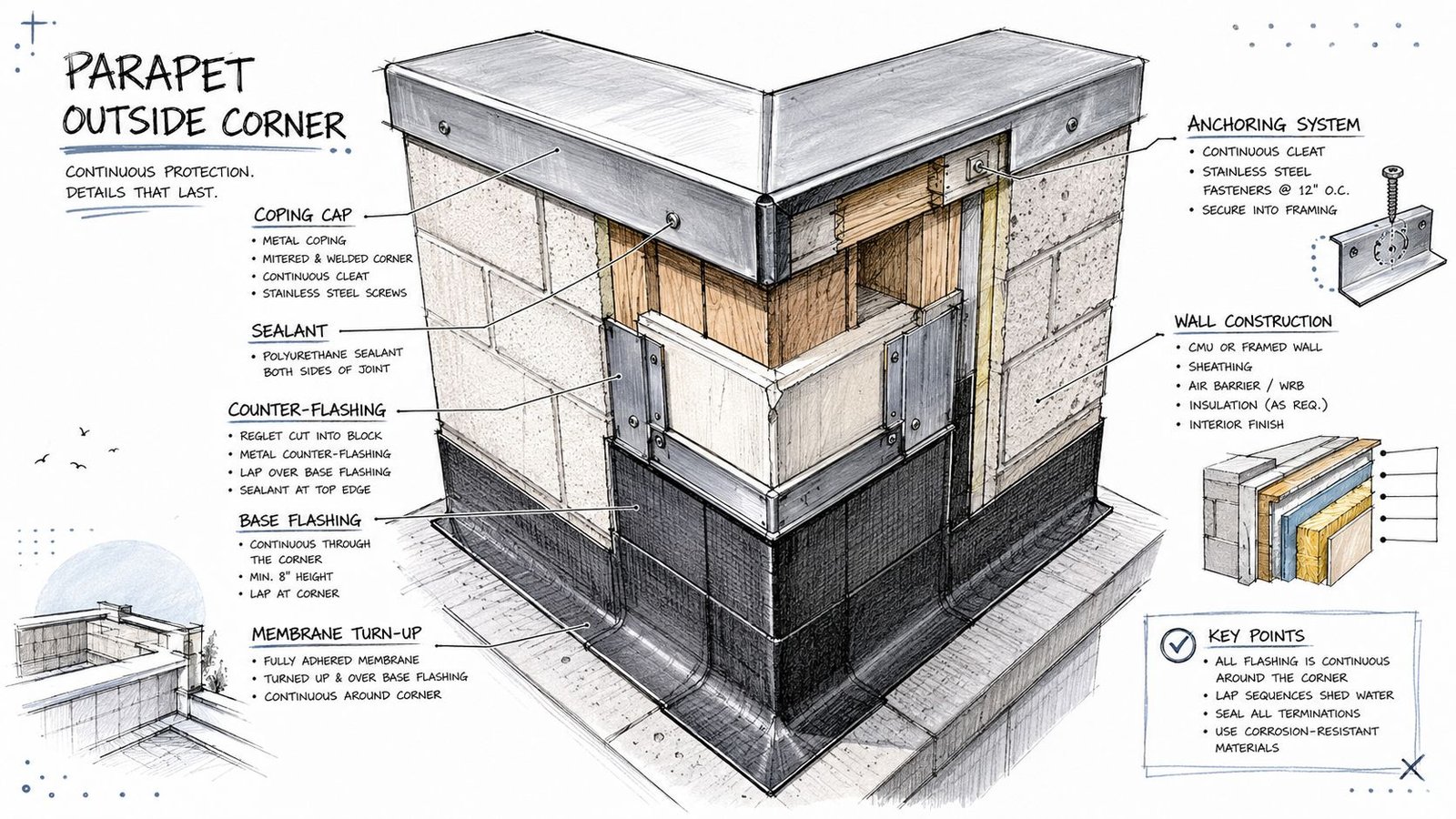
Corners need their own logic
Inside and outside corners are not note-only conditions. Coping geometry changes. Joints change. The flashing path changes. If the detail says “similar at corner,” the field still has to figure out whether that means mitered metal, prefabricated corners, folded transitions, or segmented pieces.
Tremco points out that “standard details” don't capture these project-specific complexities and recommends project-specific mock-ups and 3D diagrams because constructability and sequencing at corners and level changes are where many failures occur in its architect's guide to parapet-to-wall transitions.
Step conditions and penetrations create hidden conflicts
Roof level changes are another blind spot. When the roof steps, you don't just have one parapet detail mirrored on each side. The membrane height, transition flashing, termination logic, and coping continuity all shift.
Use separate details for:
- Inside corner conditions where water can sit or back up
- Outside corners where fabrication tolerances matter
- High-to-low parapet transitions at stepped roofs
- Rising wall intersections where the parapet dies into another wall
- Penetrations near the parapet including curbs, vents, and drains
If custom fabricated trim or panel interfaces occur near the parapet, the roof-edge detail should be reviewed with the same care you'd give custom metal panel coordination. The shape may differ, but the tolerance and sequencing issues are similar.
Production takeaway: A parapet isn't one detail. It's a family of edge and transition conditions.
Coordinating Structural and Fire Safety Requirements
The ugly version of this problem shows up late. The architect has a clean parapet section, the structural sheets add bracing after DD, the rated wall note sits in the partition schedule, and the contractor sends the RFI asking what continues above the roof line. By then, the detail is no longer a design exercise. It is a coordination failure with cost attached.
Parapets fail in CDs for two predictable reasons. The detail is drawn as finish work before the support is resolved, or the fire requirement is buried in notes instead of shown as an assembly.
Coordinate the support before you draft the finish
A tall parapet may read as a simple wall extension in elevation, but the field builds it as a loaded edge condition with attachment, bracing, and tolerance constraints. If those decisions are still floating, the coping detail is guesswork.
Show the structural relationship directly in the architectural enlargement. Do not force the contractor, plan checker, or your own CA team to reconcile five sheets to understand how the parapet stands up and what the coping fastens to.
| Coordination item | What the architectural detail should show |
|---|---|
| Stud-framed parapet | Framing depth or wall type reference, top track condition, substrate for coping attachment |
| Braced parapet | Reference to structural bracing design and where it affects build-up or clearances |
| Masonry parapet | Backup, cavity, flashing support, and coping bearing logic |
| Roof edge support | Relationship to deck, nailer, blocking, or other anchorage substrate |
That table is the minimum.
The part that saves RFIs is the interface note. If the structural set includes kicker braces, tube steel, reinforced studs, or roof-edge drag members, show where that work lands relative to insulation, air barrier continuity, and membrane termination. Otherwise the detail looks complete on paper and falls apart in shop drawing review, when everyone realizes the brace occupies the same space as the flashing build-up or coping anchor zone.
Fire requirements belong in the detail conversation
Fire-resistance at the parapet cannot live only in the wall type schedule. The top of wall condition has to read as continuous, rated, and materially consistent with the code intent. As noted earlier, the code path for rated parapets typically ties the parapet rating to the supporting wall and places limits on the materials used at the upper portion of the assembly, including coping and related metal closures.
That changes the detail in practical ways. A rated wall below with vague notes above it will draw plan check comments and contractor questions. Reviewers look for continuity. Superintendents look for buildable transitions. If neither can see where the rated assembly continues, they will ask you to define it.
A rated parapet detail should show:
- the rated wall assembly continuing to the parapet top
- the face materials at the upper parapet called out clearly
- coping, counterflashing, and closure materials that do not conflict with the rating requirement
- any change in substrate, blocking, or sheathing identified, not implied
- termination points that do not interrupt the rated line without explanation
This is also where design intent and production discipline need to meet. A note that says "match wall rating" is not enough if the section also shows combustible nailers, unspecified fillers, or an uncoordinated top condition. Draw the assembly so the reviewer can follow it in one pass and the installer can price it without assumptions.
That is how parapet details protect margin. They reduce interpretation, shorten submittal churn, and keep structural and life-safety requirements from surfacing as late RFIs.
Building Your Parapet Detail Library in Revit
Teams lose money when they redraw parapet details from scratch. They also create inconsistency. One project shows membrane turn-up clearly. Another hides it in a note. A third omits the top seal entirely because the drafter copied an old detail and adjusted only the wall hatch.
That isn't a talent problem. It's a system problem.
Build typicals by wall family, not by project
A reliable parapet flashing detail Revit workflow starts with a library organized around recurring wall and roof combinations. For example, keep separate detail groups for stud wall with exterior insulation, CMU cavity wall, brick veneer backup conditions, and any recurring multifamily podium assemblies your firm uses often.
Use drafting views or detail views with repeatable component logic. Don't rely on loose linework that only one person understands.
A useful library structure includes:
- Typical roof-to-parapet sections by wall type
- Dedicated coping details by coping family or spec basis
- Corner and transition details as separate reusable assets
- Keyed notes and legends that stay consistent across projects
- View templates that lock line weights, text styles, and scale behavior
Parameterize what actually changes
Not everything needs to flex. Some details should stay fixed to protect standards. But a few variables should be easy to update without redrawing the assembly.
Those usually include parapet height, insulation thickness, roof build-up depth, and membrane turn-up note values. If you handle those as controlled inputs, one approved library detail can adapt to multiple jobs without losing internal consistency.
The bigger gain is QA. When teams use a disciplined detail library, reviewers spend less time checking drafting noise and more time checking actual interfaces.
Use details as a coordination tool, not a decoration layer
The best Revit detail libraries support decisions upstream. They help the team catch missing substrates, unresolved coping support, and conflicts between wall types before the permit set is issued.
That's where a maintained library of Revit details becomes a production asset instead of just a drafting convenience.
Library discipline matters most at repeat problem areas. Parapets are near the top of that list.
A mature office also pairs the library with a detail issue checklist. If the typical detail is inserted, someone still needs to confirm that the project has no stepped roof, no adjacent penetration conflict, no masonry drainage omission, and no fire-rating mismatch. Standards reduce risk. They don't replace review.
Common Plan Check Corrections and RFI Traps
Most parapet corrections are predictable. That's good news, because predictable issues can be checked before issue dates instead of after redlines arrive.
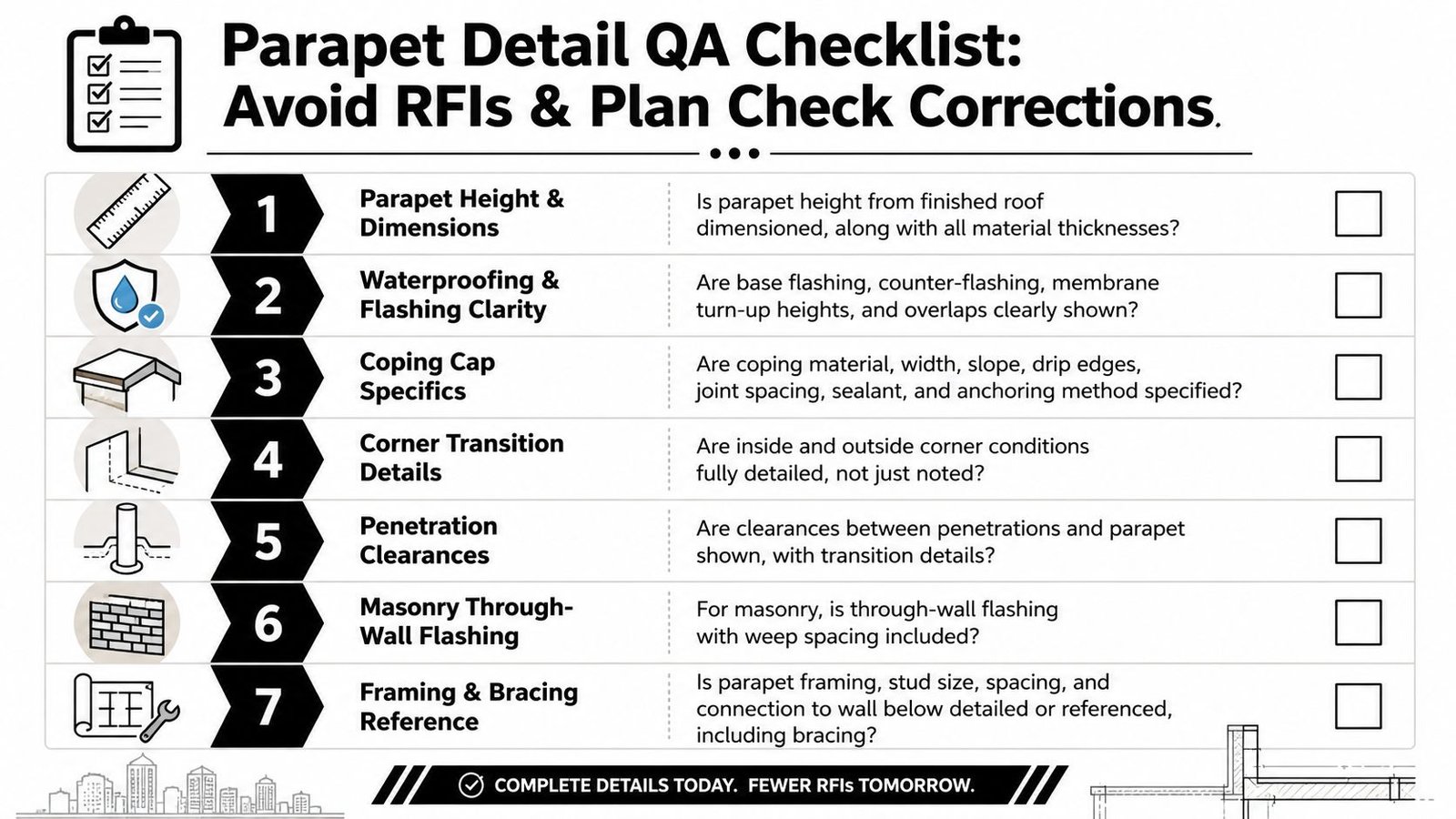
Pre-flight checklist for commercial parapet waterproofing detail
Run this before permit and again before construction issue:
- Dimension the parapet height: Show it from finished roof surface, not from a vague datum.
- Complete the coping detail: Material, width, slope, joints, and anchoring all need to appear somewhere specific.
- Show membrane turn-up clearly: Don't leave the roofer to infer the vertical extent.
- Identify the counter-flashing: Type, mounting method, and overlap need to be visible.
- Add through-wall flashing for masonry conditions: If water can enter the wall, the detail must show how it exits.
- Draw corner conditions separately: Inside and outside corners deserve their own details.
- Resolve transitions: Roof steps, rising walls, and parapet terminations need custom sections.
- Reference structural support: If framing or bracing carries the behavior of the parapet, point to it.
Where RFIs usually come from
The highest-friction RFIs tend to be simple questions with expensive consequences. What substrate receives the membrane? Where does the WRB terminate? Is the coping mechanically fastened or face-fastened? Does the top of parapet need noncombustible finish? Is there enough room between a rooftop curb and the parapet for flashing installation?
Those questions show up when the set documents geometry but not assembly.
A strong QA pass should compare the roof plan, wall sections, enlarged details, exterior elevations, and structural references side by side. If one sheet tells a different story than another, the contractor will find the gap.
Good parapet details don't eliminate every field question. They eliminate the questions the office should have answered already.
If your team is pushing commercial CDs and needs repeatable Revit production that holds up under permit review and field coordination, BIM Heroes can support that effort. If helpful, start with their architectural production services and use the conversation to pressure-test your current detail standards, QA checklists, and delivery workflow for parapet-heavy projects.
Category: Construction Coordination & Documentation