Architectural drawing standards are the shared language of design and construction. Think of them as your firm's production playbook, a set of rules ensuring everyone—from the architect in the office to the contractor on site—is reading from the same script. This isn't about restricting creativity; it's about building a system for predictability, margin protection, and operational consistency.
Why Your Drawing Standards Are Your First Line of Defense
Let's stop thinking about drawing standards as a tedious chore and start seeing them for what they are: a powerful defense against the profit killers that sink projects. Inconsistent drawings are the root cause of endless RFIs, costly change orders, and crippling permitting delays.
This isn't an academic exercise. It’s about building an ironclad system for clarity that prevents your margins from eroding, starting from day one. It's a lesson learned in the field: disciplined documentation is the foundation of production maturity.
The True Cost of Inconsistency
Every ambiguous line, misplaced dimension, or non-standard symbol on a drawing is a ticking time bomb. It creates a ripple effect that leads straight to the issues that tank profitability and damage your reputation. Without disciplined standards, you're inviting chaos.
- Endless RFIs: When contractors can't figure out your intent, they stop working and start asking questions. Progress grinds to a halt, creating a black hole for your project management hours.
- Costly Change Orders: Ambiguity leads to incorrect assumptions on site. Correcting those mistakes in the field is exponentially more expensive than fixing them in the model.
- Crippling Permitting Delays: Plan checkers are trained to find clarity. Unclear or non-compliant drawings are the fastest way to get your project sent to the back of the revision pile.
This is a lesson learned the hard way in the field. Industry data consistently shows that coordination and documentation issues are a primary driver of change orders. Enforcing standardized symbols and drafting conventions is one of the most effective ways to prevent RFIs and protect your budget.
From Chaos to Control
Implementing strong architectural drawing standards is the first step toward real production maturity. It’s what moves your firm from a reactive state—constantly putting out fires—to a proactive one where you control the flow of information. The goal is to build a rock-solid foundation that enables scalable delivery pods and predictable project outcomes.
Think of your drawing standard as your firm’s production playbook. It’s the single source of truth that guarantees every project, whether handled by a seasoned veteran or a new hire, is executed with absolute consistency.
This operational discipline isn't just for massive projects. Even small firms benefit immensely from the clarity and efficiency that good standards provide.
Core Components of a Modern Drawing Standard
| Component | Primary Goal | Impact on Production |
|---|---|---|
| Line Types & Weights | Ensure visual hierarchy and clarity | Reduces misinterpretation of elements like property lines vs. new walls. |
| Scales & Proportions | Maintain accurate representation of objects | Prevents costly measurement errors and fabrication mistakes on site. |
| Annotation Standards | Standardize text, dimensions, and callouts | Guarantees all notes are legible, consistent, and easy to find. |
| Sheet Layout & Title Blocks | Create a consistent, professional presentation | Speeds up drawing navigation and ensures all required project info is present. |
| Symbols & Legends | Provide a universal key for all graphic elements | Eliminates guesswork for contractors reading plans for the first time. |
| Compliance Guidelines | Adhere to local and national codes | Avoids permitting delays and ensures legal and safety requirements are met. |
Each of these components works together to create a cohesive and understandable set of documents. For a deeper dive into the technical side, our guide to effective BIM standards provides a framework for integrating these principles directly into your digital workflows. Ultimately, standards transform your drawings from a set of instructions into a powerful tool for risk management.
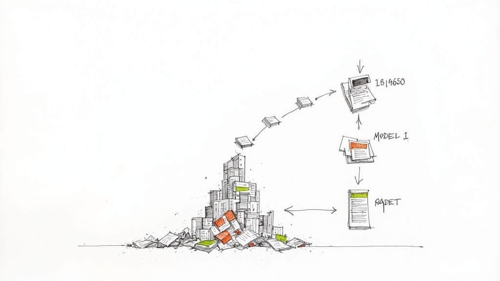
Tracing the Path from Manual Drafting to Digital Models
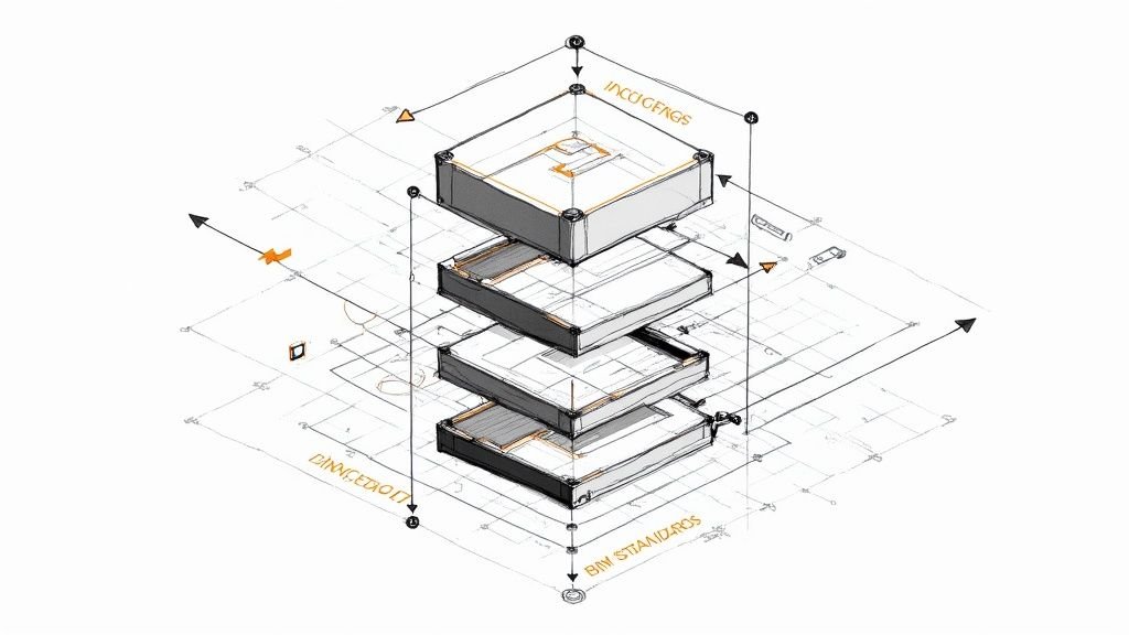
To master today's digital standards, you have to understand their origin. The rules baked into our Revit templates and CAD plot styles didn’t just appear out of thin air. They were forged over a century of trial and error on drafting boards, a story of the CAD-to-BIM evolution. This isn’t just a history lesson—it’s about how practical, on-the-ground needs shaped the tools we rely on for reliable delivery.
It all started with manual drafting, an era defined by ink, vellum, and serious discipline. Guides like the Architectural Graphic Standards (AGS) were the bibles of production, creating a universal language for things like line weights, symbols, and notation.
Every single line had a purpose, dictated by the pressure of a pencil or the specific width of a pen tip. A thick, heavy line for a wall section. A thin, delicate line for a dimension. A dashed line for an object overhead. This sophisticated system of visual hierarchy was the original defense against the profit killers that still haunt projects today.
The Shift to CAD
The arrival of Computer-Aided Design (CAD) was a massive leap forward, but it didn't toss out the old rulebook. It translated the proven principles of manual drafting into a digital world. The big challenge became replicating the nuance and clarity of a hand-drawn set on a screen and a plotter.
This is where foundational CAD standards were born:
- Layers: Digital stand-ins for Mylar overlay sheets, allowing designers to isolate systems like electrical, plumbing, and structural elements.
- Plot Style Tables (.ctb files): Code that assigned specific line weights and colors to digital layers, ensuring the final plotted drawings had the right visual hierarchy.
- Standardized Blocks: The digital version of a drafting template, making it possible to drop in common symbols for doors, windows, and fixtures with speed and consistency.
The push to CAD was driven by a need for speed and accuracy. A disciplined CAD workflow meant changes could be made in minutes, not hours, and consistency could be locked in across dozens of sheets. It was a huge step toward the operational efficiency modern firms require.
Entering the BIM Era
If CAD was about digitizing 2D drawings, Building Information Modeling (BIM) was about creating an entire 3D data environment. This evolution marked another huge shift in architectural drawing standards. The focus grew from just representing objects with lines to embedding them with intelligent data.
A line in CAD is just a line. In BIM, that "line" is a wall with data attached—material properties, fire ratings, cost, and phase information. This elevated the drawing from an instruction set to a comprehensive project database.
This deeper level of integration demanded more sophisticated standards. Firms now needed rules not just for line weights, but for family naming conventions, parameter inputs, and model organization. The goal was still the same—ensure clarity and stamp out errors—but the stakes were higher, as a single model now informed everything from energy analysis to construction sequencing.
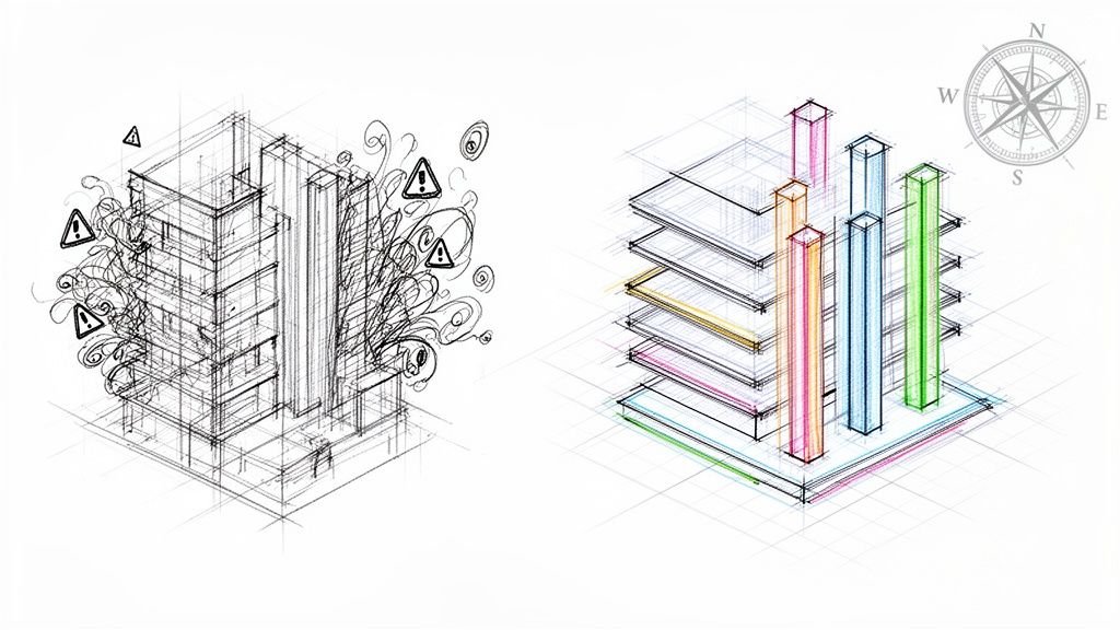
The infographic below shows how these evolving standards all serve one timeless purpose: defending projects against the things that eat away at your margins.
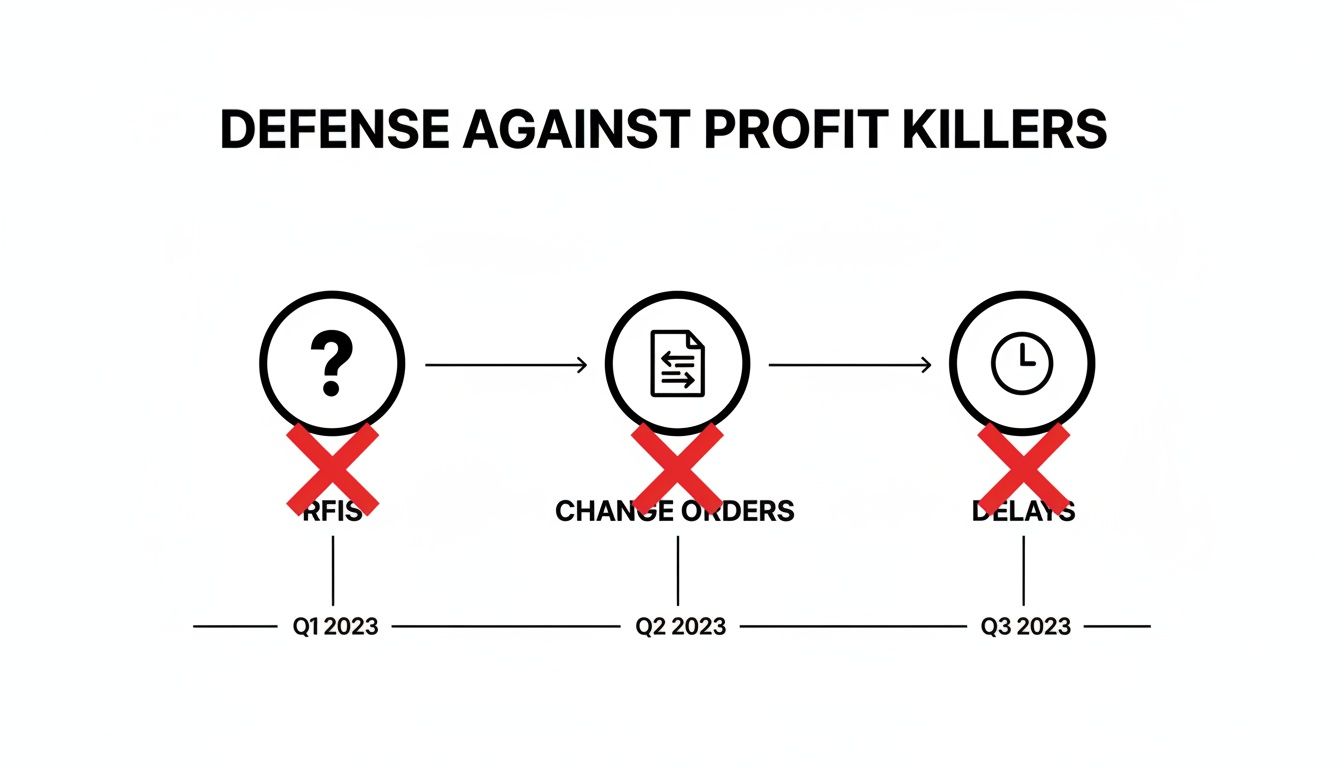
This visual makes it clear: whether drawn by hand or generated from a model, the whole point of standards is to head off costly RFIs, change orders, and delays before they happen. For a deeper dive into how precise documentation gets created, it’s worth understanding the stages of architectural design, where these standards are woven in from concept to construction.
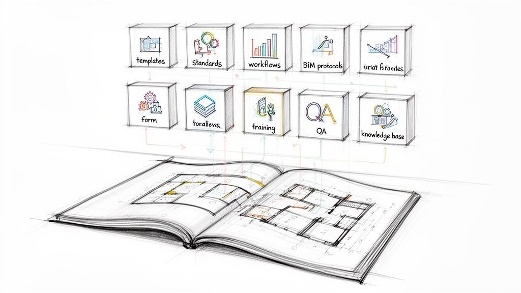
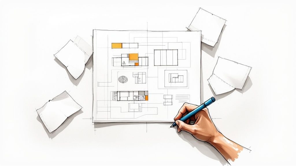
Building Your Firm's Production Playbook
Let's move from theory to action. This is where you forge real operational consistency by building your firm’s production playbook—a single source of truth that dictates how every drawing is created, reviewed, and issued.
A well-defined playbook kills guesswork and protects your margins. It ensures every project, whether handled in-house or by an outside delivery pod, is executed with precision. Think of it less as a restrictive rulebook and more as a framework for clarity. It’s the system that empowers your team to solve design challenges instead of debating annotation styles.
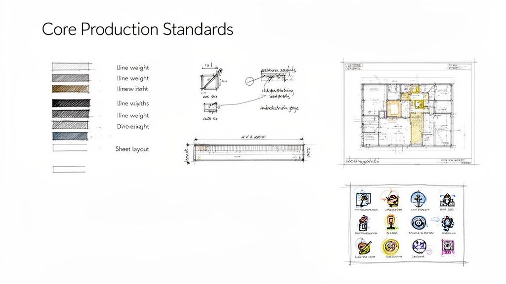
Defining Line Weights and Types
The most fundamental part of graphic clarity is a disciplined approach to line weights and types. This isn't just aesthetics; it's a communication tool. It creates a visual hierarchy that helps contractors and reviewers instantly understand the spatial relationships in a drawing.
Your playbook needs to establish clear, non-negotiable rules for:
- Object Hierarchy: Which elements get the thickest lines (like section cuts or primary structure) versus the thinnest (like hatch patterns or surface details)?
- Linetype Definitions: Assign specific linetypes for common conditions—property boundaries, overhead objects, centerlines, and demolition work.
- Digital Translation: Map these standards directly to your CAD layers or BIM object styles to guarantee consistency from screen to plot.
Without this discipline, a drawing set becomes a flat, confusing mess that just invites RFIs.
Standardizing Annotation and Dimensioning
Inconsistent annotation is a direct path to on-site errors. Your standards must provide an unambiguous protocol for all text, tags, and dimensions. Every note must be legible, professional, and easy to find. This goes far beyond just picking a font.
You need rules for text sizes, leader styles, and callout formats. Most importantly, you need a strict methodology for dimensioning. Your playbook should specify whether to dimension to the face of a stud or the centerline of a column, and that rule must be applied universally. This removes any chance for misinterpretation during framing or fabrication, preventing costly rework.
The goal is to make your drawings so clear that a contractor who has never seen your work before can understand your design intent without having to ask a single question. That’s the true test of a robust annotation standard.
The transition from manual drafting to digital tools has only accelerated this need. While nearly 100% of architectural working drawings were produced by hand in 1960, the vast majority are now created using CAD and BIM software. This shift means consistent digital standards can improve design iteration speed by over 20-30% in many offices, simply by reducing coordination errors before they multiply. You can explore more on this technological shift and its impact in the history of the evolution of architectural drawings.
Mastering Sheet Layouts and Title Blocks
A professional drawing set tells a consistent story from the first sheet to the last. Your sheet layout and title block are the "brand" of your documentation—they convey professionalism and make your sets easier to navigate. A standardized title block also serves as a critical decision checkpoint, ensuring all necessary project information is on every sheet.
Your playbook should define:
- Title Block Content: Exactly what information must be included, like the project name, sheet number, revision history, and professional seals.
- Sheet Organization: A logical sequence for your drawing set (e.g., General, Civil, Architectural, Structural) that follows industry conventions like the U.S. National CAD Standard.
- Key Plans and North Arrows: Standardized locations and styles for these essential navigational aids.
This level of organization makes your sets intuitive for permitting officials and contractors to review, a simple but effective way to prevent unnecessary delays.
Building a Robust Symbol Library
Symbols are the shorthand of architectural drawings. A standardized symbol library is essential for creating documents that are universally understood. Whether it’s a symbol for an electrical outlet, a fire-rated wall tag, or a door swing indicator, every graphic element must have a single, defined meaning.
Your playbook needs a dedicated section that serves as a legend for your entire graphic language. This library should be integrated directly into your CAD block library or BIM families, making it easy for team members to grab the correct symbols every time. This simple discipline prevents the kind of confusion that leads to incorrect installations and busts budgets. Building these components is a core part of developing scalable production systems that deliver reliable results.
Embedding Standards into Your BIM and CAD Workflows
A set of architectural drawing standards gathering dust on a shelf is useless. The real value comes when those rules are baked directly into the digital tools your team uses every day. This is how you transform a passive guide into an active, automated part of your BIM workflows that prevents errors before they happen.
This is the shift from just having standards to truly implementing them. By embedding your production playbook into your BIM and CAD software, you make following the rules the path of least resistance. It stops being about manual enforcement and starts being about systemic consistency.

Making Template Discipline Non-Negotiable
Your project templates are the single most important tool for enforcing standards. A well-built template for Revit or AutoCAD is the starting point for every new project, pre-loaded with your firm's DNA.
This concept, known as template discipline, is the key to scalable delivery. It means no project ever starts from a blank slate or, even worse, by copying an old project file filled with outdated or project-specific clutter.
Your master templates must include:
- Pre-defined View Templates: Control visibility, graphic overrides, and scale for every type of drawing, guaranteeing consistent plans, sections, and elevations.
- Loaded Component Families: Your entire library of doors, windows, and casework—all with correct parameters and graphic styles—should be ready to go.
- Standardized Annotation Styles: Dimension styles, text notes, and tags should all be pre-set to match your firm’s playbook.
This front-loads the work of maintaining standards, making consistency the default setting for every new project.
From CAD Layers to BIM Filters
In the 2D CAD world, consistency was all about strict layer management and plot style tables (CTBs). These files were the translators, turning digital colors into specific printed line weights to create the visual hierarchy on the final plotted sheet. A disciplined CTB file is still a powerful tool for ensuring that drawings print predictably.
In a modern BIM workflow, this evolves into something far more powerful: view filters and object styles. Instead of just controlling line weights, BIM allows you to manage the visibility and graphic representation of elements based on their embedded data.
A view filter in Revit can automatically highlight all fire-rated walls in a specific color or make non-structural elements appear half-toned. This isn't just a drawing trick; it's a visual QA process, making it impossible to miss critical information.
This transition from layers to data-driven filters marks a huge step in production maturity. It embeds your QA process directly into the model, helping teams spot inconsistencies long before a drawing set is issued for permitting or construction.
The Role of QA Checkpoints
Even with the best templates, you still need decision checkpoints. These are structured reviews that ensure standards are being followed at critical project milestones—think schematic design, design development, and construction document phases.
These checkpoints shouldn't be informal glances. They should be rigorous, checklist-driven audits that verify compliance with your firm’s architectural drawing standards.
- Model Health Checks: Is the model clean? Are there unnecessary families or warnings that need to be addressed?
- Drawing Set Reviews: Are all sheets using the correct view templates? Is the annotation consistent and legible?
- Clash Detection: Does the model align with the standards laid out in the project’s guiding document? You can learn more about creating a solid framework by exploring our resources on BIM Execution Plans.
As firms increasingly rely on digital tools, the physical environment where this work happens also matters. Ensuring designers have an optimal dual monitor setup can significantly boost efficiency and precision, making it easier to manage complex models and drawing sets side-by-side. This small investment in the workspace pays dividends in production quality.
Embedding standards is not a one-time setup. It's an ongoing process of refinement, turning your digital tools into active guardians of your firm’s quality and consistency.
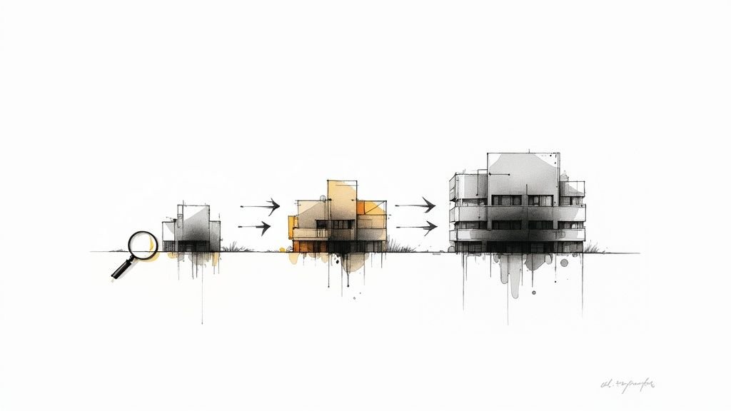
How Standards Cut Down RFIs and Permitting Delays
Think of your architectural drawing standards as a risk management tool that directly protects your two most vulnerable project phases: permitting and construction. This is where a mature, disciplined approach pays off, shielding both your timeline and your bottom line.
A plan reviewer buried under a mountain of drawings at the local building department needs to find what they need, verify code compliance, and move on—fast. When your drawings are clear, consistent, and speak a predictable graphic language, you make their job easy.
But an inconsistent set forces them to hit the brakes and play detective. A single ambiguous symbol for a fire-rated wall or a sloppy egress diagram can trigger a storm of red-lined comments, kicking off a costly and time-consuming resubmittal cycle.
Flying Through Permit Reviews
A clean, predictable drawing set is your fastest path to a building permit. For permitting prep, code officials are trained to look for consistent graphics for egress paths, accessibility clearances, and site data. If they have to guess what you mean, they’ll send it back with comments.
Those plan-check comments can delay the start of construction by weeks or even months. Using a BIM production partner that rigorously applies standardized components, annotation styles, and view templates is one of the surest ways to slash those resubmittal cycles. If you want to dive deeper, there's a fascinating history of drawing intent in American architecture on archleague.org.
The lesson learned in the trenches is simple: A permit set that’s easy to read gets approved faster.
Eliminating the RFI Black Hole
Once you break ground, the spotlight shifts to the contractor. Every Request for Information (RFI) they send is a signal that work has stopped because your drawings weren't clear enough. This is the definition of RFIs prevention. These aren't just questions; they are productivity killers that bleed schedules dry and inflate budgets.
An RFI is a failure of communication. A robust drawing standard is your best defense, ensuring your design intent is so clear it leaves no room for misinterpretation.
A strong standard kills the ambiguity that fuels RFIs. These common field issues are completely preventable with disciplined documentation:
- Dimensioning Confusion: Does that dimension go to the face of the stud or the centerline of a column? Without a firm-wide rule, different team members might document it differently on the same project, forcing the framer to stop and ask.
- Symbol Ambiguity: If a drafter uses a non-standard symbol for a light fixture, the electrical sub might install the wrong one. That leads to a change order, rework, and a heated phone call.
- Detail Mismatches: A floor plan calls out a detail number that doesn't actually exist on the detail sheet. The builder is left guessing, forcing an RFI that a simple quality check should have caught.
By enforcing a comprehensive set of architectural drawing standards, you build a system that stops these problems before they ever make it to the field. That operational consistency turns your drawings from a liability into a tool for delivering projects predictably and profitably.
Common Questions About Implementing Drawing Standards
Transitioning to a disciplined set of architectural drawing standards always brings up practical, on-the-ground questions. Moving from theory to implementation is where the real work begins. This isn’t just about creating a new document; it’s about changing habits and embedding a new system into your firm’s DNA.
Here, we’ll tackle the most common questions firms face when they decide to get serious about their production playbook. The goal is to give you direct, field-tested answers so you can build a system that actually delivers.
How Do We Get Senior Team Members on Board?
Veteran architects and technicians often have their own "proven" ways of doing things. The key is to frame new standards not as a critique, but as a strategic move to protect the firm's margins and enable growth.
Instead of focusing on restrictive rules, highlight the direct benefits to them:
- Fewer Distractions: Standardized templates mean less time fiddling with tedious setup and more time focused on high-value design work.
- Reduced Rework: Clear standards prevent downstream errors that lead to late nights fixing drawings.
- Easier Handoffs: A universal system makes it painless to delegate work to junior staff or an external delivery pod without endless explanations.
The conversation should be about operational consistency and predictability—not about who has the "right" way to draw a detail.
Should We Build Our Standards from Scratch or Use an Existing System?
There's no need to reinvent the wheel. Building on an established framework like the U.S. National CAD Standard® (NCS) provides a solid, vetted foundation. These systems have already solved many of the organizational puzzles you'll face, offering logical structures for layering, sheet organization, and notation that consultants and contractors already understand.
Your firm's unique value isn't in creating a brand-new layering system. It's in refining and customizing an industry-standard framework to perfectly suit your specific project types and BIM workflows.
Start with a proven system and then make it your own. Define your specific annotation styles, assemble your custom symbol libraries, and build your project templates around that core structure. This approach gives you the best of both worlds: industry compliance and firm-specific efficiency.
What’s the Best Way to Roll Out New Standards?
A sudden, firm-wide mandate is a recipe for resistance. A phased rollout is far more effective and gives you the chance to gather feedback and make adjustments. The process should feel collaborative, not dictatorial.
Here’s a practical, step-by-step approach that works:
- Start with a Pilot Project: Pick one or two new projects to serve as the testing ground. This creates a controlled environment to work out the kinks without disrupting the entire office.
- Involve a Champion: Designate a project manager or BIM leader who is enthusiastic about the new standards to lead the pilot team. Their success will become a powerful internal case study.
- Hold a Kickoff and Training Session: Don't just email a PDF. Conduct a hands-on training session to walk the pilot team through the new templates and QA processes.
- Gather Feedback and Iterate: After the pilot, hold a "lessons learned" session. What worked? What felt clunky? Use this feedback to refine the standards before rolling them out more widely.
This methodical approach builds buy-in and ensures the final system is practical and battle-tested. It transforms the implementation from a top-down order into a collective effort to improve how the firm operates.
Ready to build production systems that deliver clarity and consistency? We help firms implement the frameworks that protect margins and enable scalable delivery. To explore our templates, checklists, and other resources, visit us at https://www.bimheroes.com.