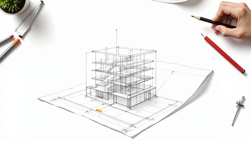
We’ve all seen it: the metal panel facade that looks stunning in the rendering. Clean lines, crisp reveals, perfectly uniform joints. Then comes the cut to the site: panels that don't align, reveals that vary in width across an elevation, and awkward transitions where two panel systems meet because nobody detailed the interface.
The gap between design intent and the built result almost always traces back to the construction documents—specifically, to details that described the typical panel field adequately but left the joints, reveals, and transitions underspecified.
Here’s a lesson learned in the field: in custom metal panel work, the field conditions are relatively forgiving. It's the transitions, terminations, and joints that make or break the facade. These are the conditions that require the most careful detailing, and they're the ones most commonly left incomplete. This guide is about closing that gap, moving decisions out of the field and back into your drawings, where clarity protects margins and guarantees outcomes.
Why Metal Panel Joints and Transitions Are the Hardest Conditions to Detail
If you’ve found detailing custom metal panels to be a genuine struggle, you’re not alone. The frustration is valid. The complexity isn’t just in your head; it’s baked into the nature of these systems.
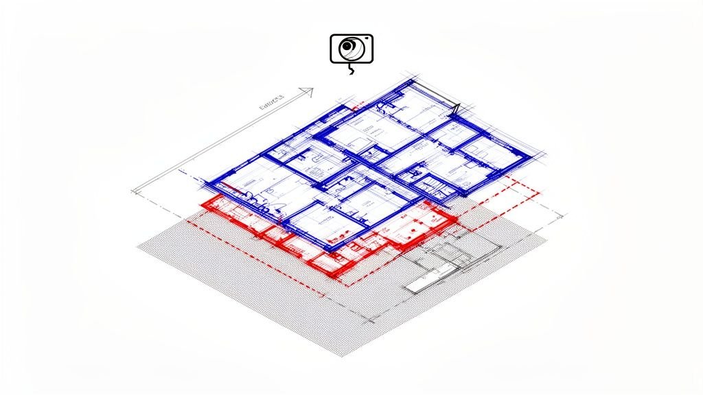
First, a single detail has to orchestrate multiple interacting components: the panel itself, the substrate framing, the attachment system, the joint treatment, and the weather barrier behind it. A mature BIM workflow is essential to coordinate these layers in three dimensions, not just as flat lines.
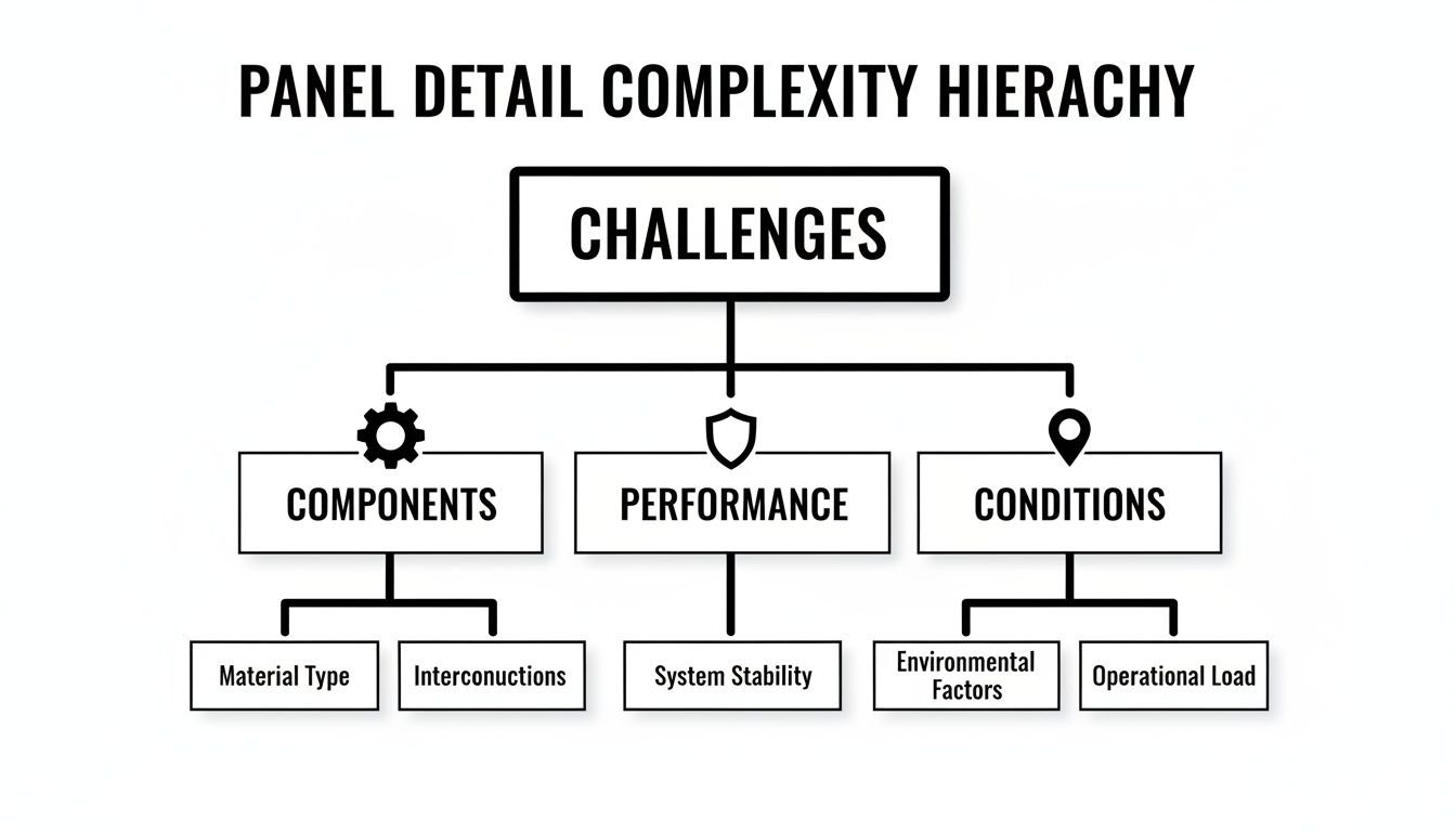
Second, joints aren't just aesthetic decisions. They are a convergence of performance requirements:
- Thermal Expansion Management: Metal moves. The joint must absorb this movement without buckling or failing.
- Water Management: The joint is either a seal or a drainage path. Getting it wrong means letting water in.
- Tolerance Accommodation: It’s the built-in "fudge factor" that absorbs minor imperfections in framing and installation.
Third, every transition condition is unique. Where a metal panel meets a window, a soffit, a different cladding material, or a roof edge, the geometry and performance requirements change completely.
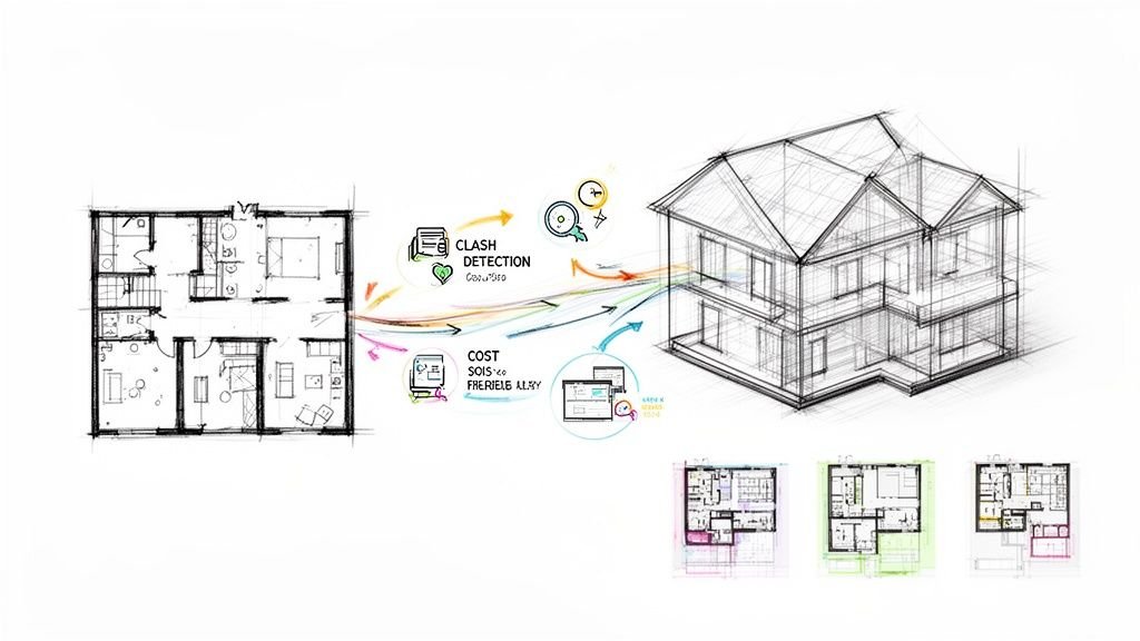
The core challenge is that many architects detail the typical panel field condition well but treat transitions as variations to be worked out later. This means they get worked out on site, often badly, leading to a cascade of RFIs and change orders. Fabricators and installers need enough information to execute these conditions without interpretation. Ambiguity gets resolved in the field, and field resolutions rarely match design intent, compromising both aesthetics and margin. A disciplined documentation process is the only way to ensure operational consistency. This front-end clarity is a fundamental part of any successful constructability review.
Understanding the Types of Joints in Metal Panel Systems
To create details that prevent RFIs, you need a clear taxonomy of joint types. Each represents a distinct strategy for managing water and movement. Treating them as interchangeable is a path to field problems.
Open Joints
An open joint is a deliberate gap between panel edges, typically 3/8 inch to 3/4 inch wide. This is the cornerstone of a true properly detailed rainscreen cladding system, where the joint is not sealed. Its purpose is to allow water to drain through to a drainage plane behind. The waterproofing work is done by a continuous, properly lapped weather barrier.
Your detail must show:
- Joint width and panel edge condition.
- Weather barrier continuity behind the joint.
- Any backer rod used for alignment.
- A clear drainage path to the exterior.
Sealed Joints
Here, panel edges are brought close together (typically 1/4 inch to 3/8 inch wide) with a sealant joint between them. This is common where the panel system is the primary weather barrier. However, sealed joints are maintenance-intensive; sealant degrades over time and needs periodic replacement. The success of a sealed joint hinges entirely on a robust QA process and installer precision.
A bulletproof detail must specify:
- Joint geometry including sealant depth-to-width ratio.
- Backer rod location and size.
- Sealant type and any surface preparation notes.
- The panel edge preparation required for proper adhesion.
Shadowline and Reveal Joints
A shadowline or reveal joint is a recessed condition that creates a visible shadow line. While often an aesthetic choice, it has significant technical implications. Reveal depth, width, and the condition at the back all need to be detailed.
If the reveal is open to weather, it functions like an open joint and needs a drainage path. If it's closed, it must be airtight. The key challenge is consistency. A crisp, uniform reveal line across an entire elevation requires tight substrate framing tolerances. Your detail must communicate this requirement, not just show the finished condition.
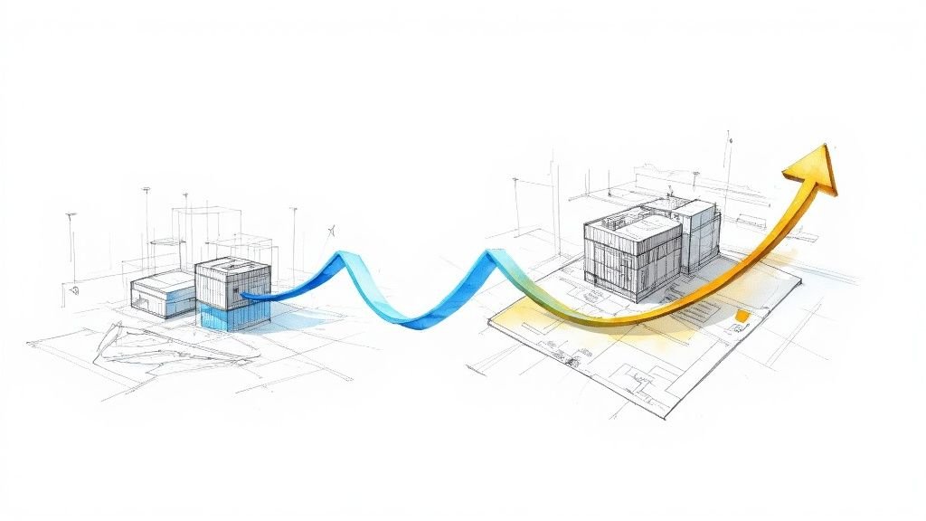
The North American fabricated metal products market is projected to grow substantially, as noted in the fabricated metal products market analysis on Mordor Intelligence, making this level of detailing skill even more critical for firms aiming to deliver high-quality facades.
Detailing Reveals: Where Design Intent Meets Construction Reality
Reveals are one of the most common areas where construction documents fall short, leading to on-site disappointment. An architectural drawing shows a clean line, but the detail must define exactly how that line is achieved.
Reveal Width and Depth
The detail needs to account for stacked tolerances: panel fabrication tolerance, substrate framing tolerance, and installation tolerance. A nominal 3/4-inch reveal can easily vary by ±1/4 inch if these tolerances aren't managed through disciplined documentation. The reveal depth affects how the shadow reads on the facade; a shallow reveal in bright sunlight looks very different from a deep one. Your detail must show the panel edge profile—square cut, returned edge, or formed reveal edge—because this dictates the panel fabrication process.
Substrate Alignment
Reveal consistency depends entirely on the substrate framing being installed to tight tolerances. It’s not enough to draw the finished condition; the detail must communicate the tolerance requirement to the installer. For long horizontal reveals, the detail should specify how the line is maintained across panel joints and at intermediate supports. This is a critical decision checkpoint in the QA process.
Backing Conditions
What’s behind the reveal matters, especially in open systems where the back is visible. A visible housewrap behind a designer reveal is rarely the intended aesthetic. If the weather barrier is behind the reveal, it must be shown. Some systems use a painted backer panel or closure piece to control what's visible—this must be shown explicitly in the detail. It’s this level of foresight that prevents costly field fixes and protects predictability in the final outcome.
Transition Conditions: The Most Complex Details in Metal Panel Work
This is where facade documentation truly proves its worth. Transitions are the most technically challenging conditions and the source of most RFIs and performance failures. Getting them right on paper is the single most effective way to protect your design intent and project margin.
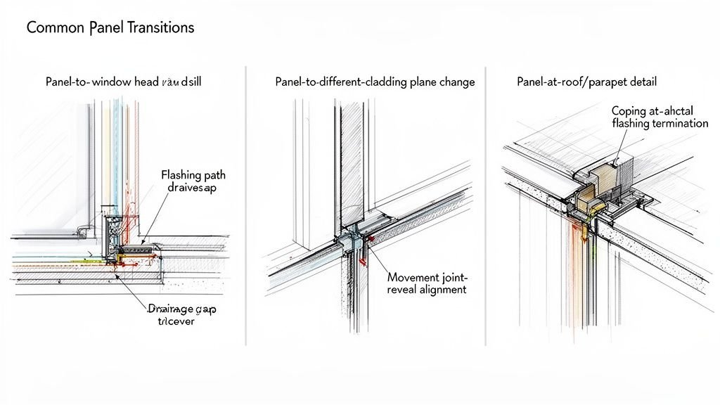
Panel to Window
This is the most common and most frequently under-detailed condition. The panel must terminate cleanly at the window frame, and the sill, jamb, and head conditions all behave differently and require separate details.
- Sill Condition: How does water that gets behind the panel exit? The detail must show sill flashing directing water out, not into the wall.
- Jamb Condition: Is there a reveal, a sealant joint, or a trim piece? Each option requires a different detail defining the geometry and materials.
- Head Condition: The detail must show a head flashing that sheds water away from the window and integrates with the weather barrier.
Thermal bridging at this interface is a common performance problem and must be addressed.
Panel to Different Cladding Material
Where metal panels meet brick, stone, or another system, the detail must resolve plane alignment, joint treatment, and water management. Different claddings sit at different depths; the transition must solve this change in plane elegantly. Movement joints between dissimilar materials are often required to accommodate differential movement without compromising weather performance.
Panel at Building Corners
Exterior corners can be a formed corner panel, a mitered joint, a trim piece, or an open condition. Each reads differently and requires a unique detail that accounts for thermal movement. Interior corners are often overlooked but are critical for weathertightness. The detail must show how panels terminate and how the corner is sealed.
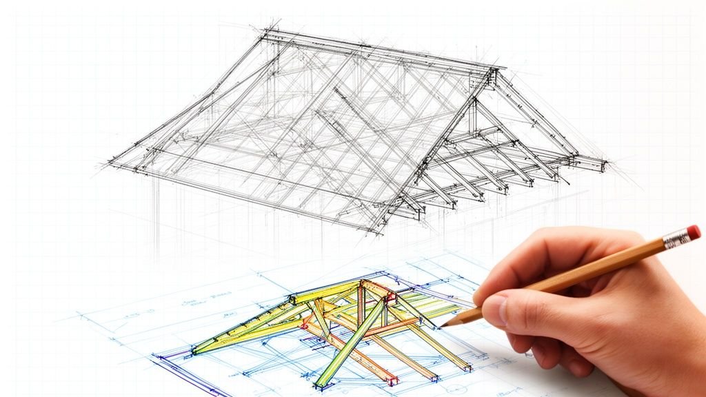
Panel at Roof Edge and Parapet
This is a critical waterproofing condition. The detail must show how the panel system transitions to the roofing membrane, how the cap flashing integrates with both, and how water is prevented from getting behind the panel. This is where a clear understanding of components like those in this guide to flashing types for roofing becomes invaluable.
Panel at Grade and Base Conditions
The base detail must show flashing that prevents water from wicking up from below. A reveal or shadow line at the base is a common design move; the detail must show how it's achieved and, crucially, how it drains.
The demand for customized solutions continues to grow, a trend supported by findings on the North America metal fabrication market research on MarketDataForecast.com. This underscores the need for production partners who understand these complex conditions.
What the Drawings Need to Show: A Documentation Checklist
This checklist is a minimum standard for any facade package involving custom metal panels. Each detail should be drawn at a scale that shows the full assembly (1.5" or 3" to the foot), not just a schematic. This is about building with template discipline to ensure consistency.
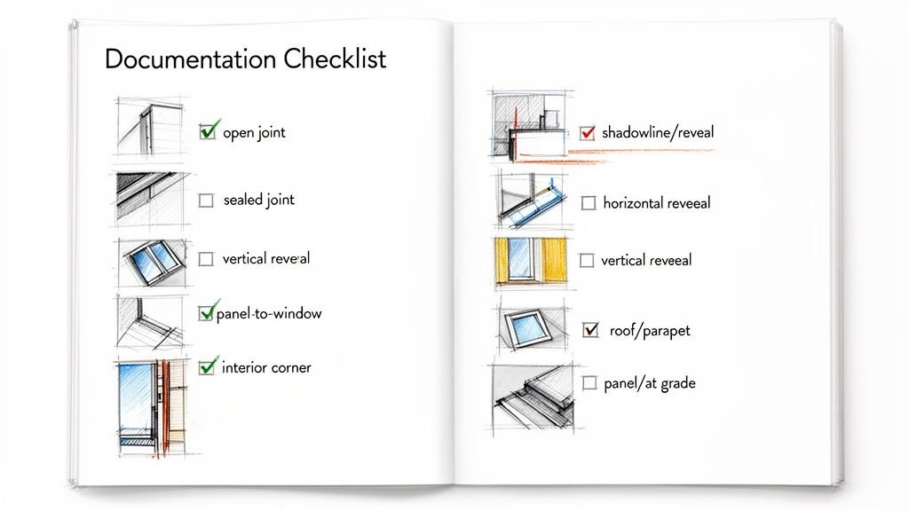
- Typical open joint detail: Show panel edge, joint width, backer, and weather barrier.
- Typical sealed joint detail: Specify sealant, backer rod, joint geometry, and surface prep.
- Horizontal reveal detail: Show width, depth, panel edge profile, and substrate tolerance.
- Vertical reveal detail: Same as horizontal, but addressing drainage.
- Panel to window: Provide separate details for sill, jamb, and head conditions.
- Panel to dissimilar cladding: Show plane alignment, joint treatment, and movement accommodation.
- Exterior corner: Detail the corner panel or trim and thermal movement strategy.
- Interior corner: Show panel termination and weather seal continuity.
- Roof edge or parapet: Detail the panel termination, cap flashing, and membrane integration.
- Base condition: Show the panel termination, base flashing, and drainage path.
The precision required for these details is made possible by modern fabrication technology. As noted in the sheet metal fabrication equipment market growth at Grand View Research, investment in this area continues to rise, enabling the tight tolerances your drawings must demand.
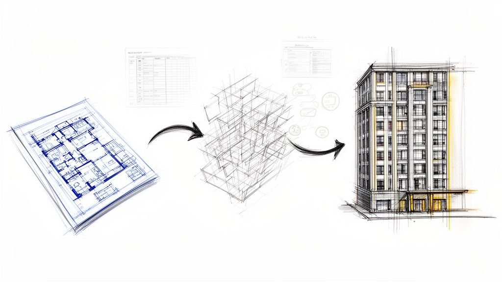
How BIM Heroes Approaches Metal Panel Detail Documentation
At BIM Heroes, we produce construction detail packages for metal panel systems that aren't just drawn to look right; they're modeled in Revit to be built right. We don't sell hours; we sell clarity, systems, and reliable delivery.
Our approach is built on production maturity. We operate as an embedded production partner, developing detail libraries for joints, reveals, and transitions that ensure consistency across a project. We understand US building envelope standards and the critical coordination between the panel system, substrate framing, and waterproofing. Our CAD-to-BIM evolution means we model at a level of detail required for fabrication coordination and permitting prep, preventing RFIs before they happen.
We structure our teams into scalable delivery pods, ensuring the same high level of detail whether we're documenting a single storefront or a complex mixed-use facade. By staying involved through detail development and drawing production, we provide the operational consistency and predictability that protects your margin and ensures the facade you designed is the facade that gets built. For projects requiring complex BIM coordination, our systems provide the clarity needed for successful execution.
The Takeaway: From Intent to Built Reality
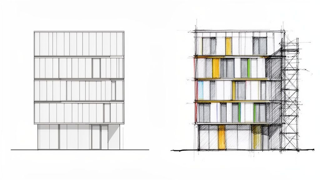
Return to the opening image: the facade that looks exactly like the rendering versus the one that doesn't. The difference is almost always in the details—specifically, whether the joints, reveals, and transitions were fully resolved on paper before anyone started installing panels.
Metal panel facades are among the most detail-sensitive building envelope systems in use today. The architects and production teams who treat these transition conditions with the same rigor as the typical field conditions will consistently deliver facades that match the design intent. The ones who leave these conditions to the installer will consistently be disappointed by what gets built. The final product is a direct reflection of the discipline in the documentation.
Working on a project with custom metal panel cladding? Let's talk about how BIM Heroes can support your detail development and facade documentation.