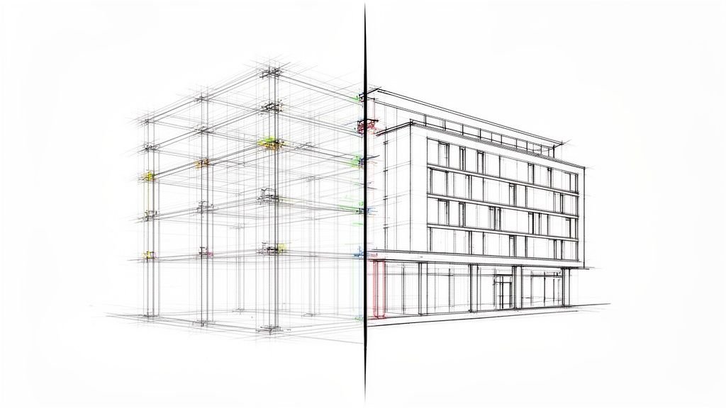
A reliable framing plan in Revit isn't a collection of 3D lines; it's a parameter-driven system built for predictability. When beams refuse to align with levels or framing jumps unexpectedly, it’s not a software glitch. It's a symptom that the underlying mechanics—the families, types, and parameters—are misunderstood or misused.
This isn’t a beginner’s guide. We’re going under the hood to break down how Revit framing behaves at a mechanical level, explaining why so many production pain points stem from misusing its core system.
Why Your Framing Plan in Revit Keeps Breaking
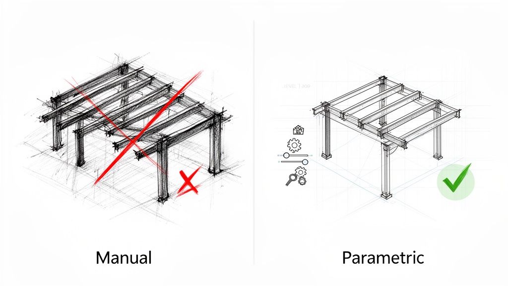
The most common point of failure for production teams is treating Revit framing elements like simple geometry. This old-school, CAD-centric mindset—nudging things into place until they look right—is the direct cause of broken models, coordination clashes, and unreliable drawings.
Revit doesn’t just see lines; it sees intelligent components governed by a strict hierarchy of families, types, and parameters. Every so-called "glitch" is just the software logically resolving a command that contradicts its own rules.
This disconnect between visual tweaks and systemic control is where project margins get vaporized. A beam that looks right in plan but reports the wrong offset in a section isn't just an annoyance; it's a data integrity failure that leads to RFIs, permitting delays, and rework. The challenge is to stop forcing geometry and start systematically defining its behavior.
The Real Source of Framing Errors
Frustration with Revit framing almost always traces back to a few specific misunderstandings. These aren't complex BIM theories; they are the fundamental mechanics of how structural elements are designed to behave. Pinpointing these issues is the first step toward a predictable Revit framing workflow.
When things go sideways, it’s usually because of one of these culprits:
- Inconsistent Alignments: Beams not aligning with levels or grids? This is often a result of incorrect family hosting or poorly defined reference planes inside the family itself. The element is unmoored from the project's coordinate system.
- Unexpected Element Behavior: Framing that jumps unexpectedly is a direct result of hosting relationships working exactly as designed. The beam is hosted to a column, and the column moved. The problem wasn't the software; it was the initial placement decision.
- Inaccurate Schedules and Tags: If your schedules report wrong sizes or tags behave inconsistently, it’s a classic symptom of misusing instance parameters for properties that should be type-driven. This bad habit often creates hidden geometry errors that break Revit models over time.
To help debug broken models, this table connects common symptoms to their root causes within the Revit system.
Common Framing Problems and Their Root Causes
| Symptom You See | Root Cause in the System | Where to Focus the Fix |
|---|---|---|
| Beams "jump" when a column moves. | Hosting Relationships. The beam is hosted to the column and is following its host, as designed. | Break the hosting relationship or re-host the beam to a stable grid or level instead. |
| Elements won't snap to a level. | Family Hosting Behavior. The family might not be level-hosted, or its internal reference planes are misaligned. | Edit the family to ensure it's built on the correct work plane and reference planes are properly defined. |
| A schedule shows dozens of unique beam sizes. | Instance vs. Type Parameters. Someone used instance parameters to override dimensions instead of creating new types. | Audit the model for overrides. Create new, standardized family types for each required size. |
| Tags show incorrect elevation data. | Incorrect Spot Elevation Settings. The tag might be reading the top of steel instead of the bottom, or it’s referencing the wrong level. | Check the tag family and its type properties to ensure it's referencing the correct information. |
Spotting these patterns is half the battle. Once you understand why the model is misbehaving, you can start enforcing the discipline needed for operational consistency.
Guesswork creates geometry, but discipline creates coordination. Revit framing works reliably only when families, types, and parameters are understood and controlled.
Ultimately, a stable framing plan in Revit is the outcome of production maturity. It requires a disciplined approach where every element's behavior is intentionally defined. This guide will break down the mechanics of this system, moving you from fighting the software to making it a reliable partner in delivering projects with predictability.
Understanding Family Categories and Hosting Behavior
I’ve seen it a thousand times: a persistent, maddening problem in a framing plan in Revit—unexpected joins, broken schedules, elements that just won’t cooperate. Almost every single one of those issues can be traced right back to the family itself.
Getting the fundamentals right at the family level isn't just a best practice. It’s the only way to build a predictable and profitable production workflow. It all starts with the family category.
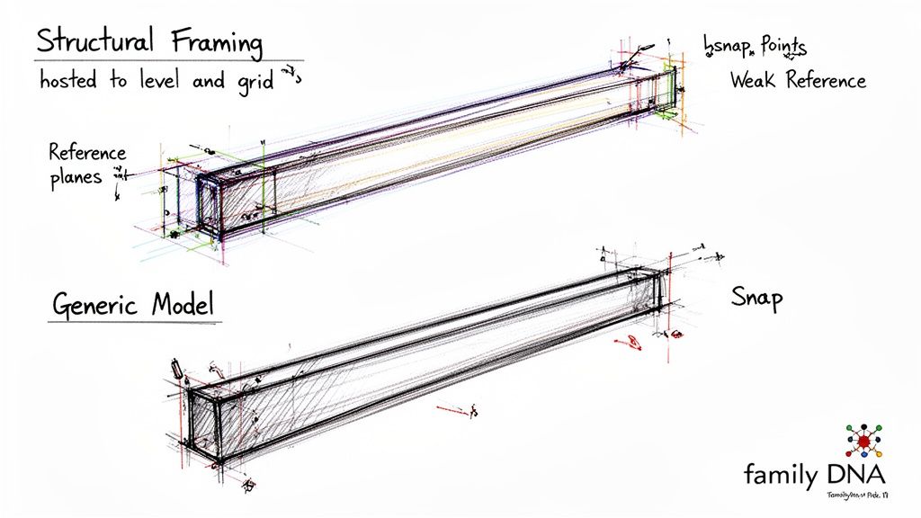
Choosing between Structural Framing and a Generic Model isn’t just an organizational choice. It’s a decision that defines the element's DNA. The correct category unlocks specific, critical behaviors: a Structural Framing family inherently understands how to join with columns, how to be coped, and how to generate an analytical line. Using the wrong category is like trying to make a door behave like a window—you can force it to look similar, but it will never function correctly within the system.
The Unbreakable Rules of Hosting
Beyond the category, an element’s hosting behavior determines its stability. This is a critical decision checkpoint that many teams miss. A beam drawn freely in space is an island. A beam hosted to a level and a grid line is an integrated component with predictable behavior.
When a beam "jumps" after someone moves a column, that’s not a bug. That's the hosting logic working exactly as designed. The beam was told to follow that column, so it did. The secret to a stable model is to intentionally define these relationships from the start as part of a disciplined template.
Beams should be hosted to the primary structural grid and their associated levels whenever possible. This anchors them to the project's coordinate system, ensuring they stay put. This discipline alone prevents the cascading errors that eat up hours in your QA process.
A framing element's behavior is a direct consequence of its family category and hosting logic. If the element misbehaves, it's because it was built or placed with the wrong instructions. The model isn't broken; the instructions are.
Why Reference Planes Are Non-Negotiable
Drilling down into the Family Editor, the hierarchy of reference planes governs everything—from snapping behavior to how dimensions are controlled. This is where the real mechanics of Revit framing families are defined. It’s not about drawing an extrusion; it’s about building a parametric skeleton that controls the geometry.
Within a family, reference planes are set as "Strong," "Weak," or "Not a Reference." This hierarchy is critical to get right:
- Strong References: These are the primary planes Revit snaps to first when placing or aligning the element. The centerline and top/bottom of a beam should always be strong references.
- Weak References: These are secondary planes, useful for dimensioning or less critical alignments.
- Not a Reference: These planes are purely for construction inside the family and are invisible to the project environment.
Mismanaging this hierarchy is a common source of frustration. If a modeler can't snap a dimension to the edge of a beam, it’s almost certainly because that edge wasn't defined by a strong or weak reference plane inside the family. A disciplined approach to family creation pays dividends in production maturity. You can explore these principles in our comprehensive Revit family creation guide.
This level of control is the foundation of a mature CAD-to-BIM evolution. It ensures your Revit data is reliable and interoperable from day one. Once you understand that every framing element is a product of its category, hosting, and internal reference planes, you shift from fighting the model to directing it. That control is the only way to protect your margins.
Type vs. Instance Parameters: The Core of Model Discipline
This is where so many teams stumble. To build a framing plan in Revit that doesn't become a liability, you must master the difference between a Type parameter and an Instance parameter. Misunderstanding this is the number one reason models get bloated, schedules break, and QA becomes a nightmare.
Here’s the simplest way to think about it: Type parameters are for rules. Instance parameters are for exceptions.
When you change something at the Type level—like the 'b' (width) and 'h' (height) of a W18x35 beam—you're setting a standard for every element of that type. Tweak the 'h' value in the Type Properties, and every single W18x35 beam in your project updates instantly. That’s how you maintain operational consistency.
Instance parameters, on the other hand, are for one-off adjustments. A perfect example is the 'Start/End Level Offset'. You use it to nudge a single beam up or down for a unique connection without affecting any other beam of the same type.
Where the Workflow Breaks Down
Chaos kicks in when modelers treat these two parameter types as interchangeable. It’s a bad habit, usually from a CAD mindset of "just make it look right," but it injects silent errors that corrupt your model’s data integrity.
I’ve spent countless hours debugging models plagued by these exact mistakes:
- Bloated Family Libraries: Someone needs a beam with a 2" top offset. Instead of using the 'z-Offset Value' instance parameter, they duplicate the beam type and call it "W18x35 – 2in offset." The project is now bogged down with redundant types for what should be simple instance tweaks.
- Corrupted Schedules: A modeler forces a change to a beam's dimensions directly in the properties palette, overriding its Type parameters. The beam looks right in plan, but now it’s a rogue element. It no longer matches its own type definition, which means schedules will report the wrong size and break quantity takeoffs.
- Unpredictable Updates: When you rely on instance overrides, you lose all systemic control. Updating the structural design becomes a painful, element-by-element slog instead of a quick, type-based change. That inefficiency eats directly into your margin protection.
In a disciplined BIM workflow, you never create a new family type for a condition that can be controlled by an instance parameter. That single rule is a firewall against model corruption.
Controlling Justification and Offsets with Precision
To master instance-level control, you must understand how justification and offset parameters interact with a family's internal skeleton—its reference planes. These are your tools for fine-tuning a beam’s position without breaking its core definition.
For Revit structural framing, these are the key Revit beam parameters you'll use constantly:
- Justification (y and z): This tells the beam which of its internal reference planes should align with the line you draw. Setting 'z Justification' to 'Top of Beam' ensures the top of the steel follows your placement line, critical for framing under a slab.
- z-Offset Value: This moves the entire beam up or down from its justification plane. It's the clean, correct way to add a consistent offset.
- Start/End Level Offset: These are designed specifically for sloped beams. They control the vertical position of each endpoint relative to the host level. Using them for a simple flat offset is a common mistake and leads to unexpected behavior.
These instance parameters are how you tell a single beam how to behave in its specific spot. This discipline ensures your framing plans produce geometry that is not only visually correct but also packed with reliable data for schedules, tags, and coordination. It's why our internal model health and QA/QC checklists always include an audit for incorrect parameter usage.
Understanding this hierarchy—Family Category > Family Type > Instance Parameters—is what separates a production team that fights Revit from one that directs it with clarity and precision.
How Revit Resolves Joins, Coping, and Cutbacks
Framing elements rarely exist in a vacuum. How Revit handles their interactions—the joins, copes, and cutbacks—can feel maddening if you don't grasp the logic behind it. It’s not random; Revit follows a strict, automated hierarchy to decide which beam cuts which. Getting this wrong is a surefire way to produce an unreliable framing plan in Revit.
Revit's default behavior for joining structural elements is based on a pecking order. It weighs factors like the family type (a column usually cuts a beam), material strength, and even the placement sequence. This automation is a decent starting point, but it often needs to be manually overridden to reflect actual construction intent.
So, when you see a beam slicing clean through a girder it’s supposed to frame into, that's just Revit following its internal rules. This is where many production teams hit a wall, burning hours manually adjusting geometry instead of using the tools designed to control these interactions and prevent RFIs.
Taking Control with the Beam and Column Joins Tool
The Beam/Column Joins tool is your go-to for dictating the join hierarchy. It lets you cycle through the available join orders for selected elements, forcing a beam to cut a column or vice versa. It’s a simple concept, but it only works if the elements are part of the same join calculation.
If the tool seems to do nothing, it's almost always because the elements aren't truly touching or intersecting. A tiny, imperceptible gap is all it takes to prevent Revit from recognizing that a join should even exist. It's a classic case of modeling that looks right but isn't geometrically precise.
Revit’s join logic is unforgiving. It operates on geometric truth, not visual approximation. If elements aren’t truly intersecting, the automated and manual join tools simply have nothing to act upon.
This decision-making process is critical for maintaining a healthy model. The flowchart below visualizes the core choice: should a change apply to a single, unique beam, or to all beams of that specific size?
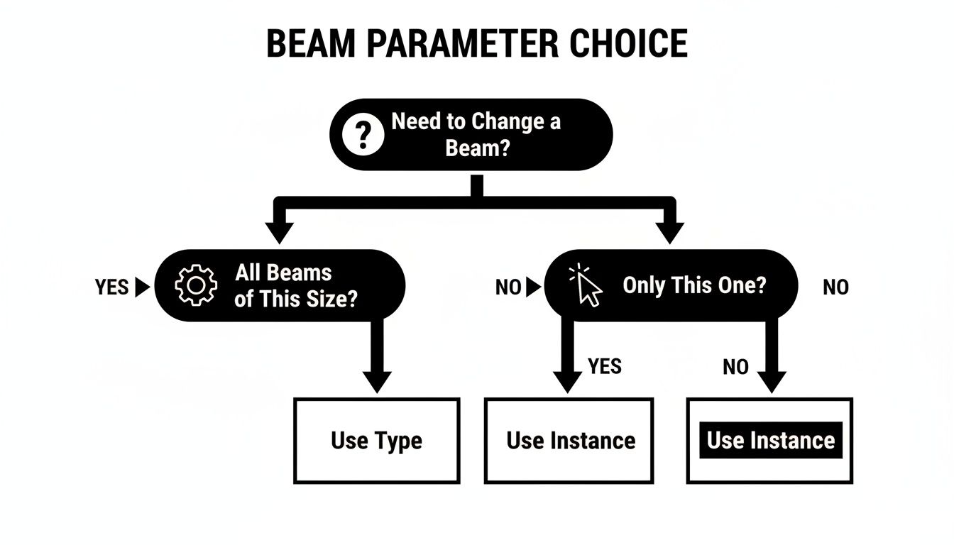
This reinforces a fundamental rule for model health: instance parameters are for unique exceptions, while type parameters enforce consistent standards across your project.
Understanding Coping and Join Cutbacks
When beams frame into one another, you need to show the notch—the cope—for fabrication. The Apply Coping tool automates this. But just like the join tool, it demands precision. The elements must intersect for it to work. If it fails, your last resort is creating manual voids, but you'll sacrifice all parametric control.
This is completely different from the Start/End Join Cutback instance parameters. It’s crucial to understand that these parameters do not change the physical geometry. Instead, they pull back the element's analytical line. This distinction directly impacts the structural engineer.
A common mistake is using a negative cutback value to "extend" a beam to a column. This creates a visual connection, but it leaves the analytical model completely disconnected. It's a guaranteed way to cause a failed structural analysis and create major headaches during coordination. These cutbacks are purely for refining the analytical model.
To clarify when to use which parameter for adjusting your framing, here’s a quick guide. Using the wrong one can lead to modeling errors and permitting prep issues.
A Guide to Framing Adjustment Parameters
| Parameter Name | Parameter Type | When to Use It | A Common Mistake to Avoid |
|---|---|---|---|
| Start/End Join Cutback | Instance | To adjust the analytical line's end position without changing the physical geometry. Ideal for fine-tuning the structural analysis model. | Using a negative value to visually "stretch" a beam to a column. This disconnects the analytical model. |
| Start/End Extension | Instance | To physically extend or shorten a beam's geometry at its ends. Useful for unique, one-off conditions where a beam needs to be longer or shorter than its defined length. | Applying it to many beams that should be a standard length. This creates inconsistencies and maintenance headaches. |
| Justification | Instance | To control the alignment of a beam relative to its location line (e.g., top, center, bottom). | Changing justification without understanding how it affects the beam's relationship with other elements, causing clashes. |
| Geometric Position | Type | To define the standard cross-sectional alignment for all beams of a particular type (e.g., y-z justification). | Modifying the type parameter when you only need to adjust a single, specific beam instance. |
Understanding the specific purpose of each parameter is key to building an accurate and reliable structural model. Misusing them often leads to rework and confusion between architectural and structural teams. Recent industry data shows that Revit 2022 and 2023 were used in approximately 70% of all projects across major markets. This widespread use means engineering partners expect a clean analytical model. You can learn more about these adoption statistics and their impact. Mastering these tools is essential for producing a clean coordination model and aligning your Revit framing workflow with modern production standards.
The Downstream Impact on Schedules and Coordination
The real test of any framing plan in Revit isn’t how it looks on screen—it’s whether the data it generates is reliable. A model can look perfect, but if it spits out faulty schedules, inaccurate tags, and a broken analytical model, it's a massive liability. This is where poor parameter discipline hits your margins and makes project outcomes unpredictable.
When you misuse Type and Instance parameters, the first thing to break is your schedule. A structural framing schedule should be a clean list of standard parts. But when modelers create one-off types just to handle a simple offset, the schedule balloons into a mess of near-identical entries like "W18x35 – 2in offset," turning quantity takeoffs into a guessing game.
This kind of inconsistency undermines the model as a single source of truth and defeats the purpose of a mature BIM workflow.
Why Your Tags and Schedules Lie
Think of tags as direct windows into an element's parameters. When a tag shows the wrong size or elevation, it's not a glitch in the tag family—it's reporting the bad data it was fed from a poorly managed element. If a beam's dimensions were overridden at the instance level, the tag will obediently display that override, creating a direct conflict with the official type mark.
This leads to chaos on the construction documents. You might have a beam tagged as a W18x35 but scheduled as something else entirely, all because of an invisible parameter override. Preventing these RFIs is simple: enforce discipline.
Instance parameters are for location and orientation. Type parameters are for size and material specification. Visual accuracy means nothing if schedules are wrong, tags are inconsistent, and the analytical model is disconnected. The goal isn't just geometry; it's contract-ready documentation.
The Disconnected Analytical Model
Perhaps the most critical downstream failure is the gap between the physical and analytical models. Architects and modelers see the 3D geometry, but structural engineers rely on the analytical model—a simplified schematic of lines and nodes—for their analysis software. These two representations must be aligned.
Sloppy modeling practices create a chasm between them:
- Incorrect Offsets: Using a 'Start/End Level Offset' to flatten a beam instead of the 'z-Offset' can shove the analytical line away from its intended node point.
- Improper Join Cutbacks: Faking a connection by using a negative join cutback might make the physical model look right, but it can leave the analytical lines feet apart.
- Hosting Errors: Beams hosted to the wrong level or element can create analytical nodes that just float in space, completely unattached to the main structure.
These errors make the analytical model useless, forcing the engineering team to rebuild it or send the model back for rework. This stalls the project and creates friction, all because the initial modeling lacked discipline. With BIM adoption on the rise—73% of UK respondents and 80% of large US firms are using it—delivering a clean, coordinated model isn't optional. You can discover more insights about global BIM adoption here.
A disciplined approach to creating a framing plan in Revit is about building a scalable delivery system. It ensures the data flowing from your model is consistent and ready for coordination, protecting your firm's reputation. For teams looking to tighten up their workflows, our guides on structural coordination and model health offer actionable checklists.
When families, types, and parameters are handled with intent, the model transforms from a 3D picture into a predictable and profitable project asset.
Ready to improve your team's Revit framing discipline?
Faulty parameters and inconsistent families are often the hidden source of model errors and coordination headaches. Our Revit Framing Family Audit Checklist provides a clear, technical framework for vetting your components to ensure they are built for production reliability.