An effective HVAC duct layout drawing is more than a plan; it's a buildable blueprint that prevents costly on-site conflicts and protects project margins. It ensures every duct, transition, and piece of equipment is placed with full consideration for structure, clearances, and other trades, transforming a theoretical design into a constructible reality.
Why Your Ductwork Drawings Create On-Site Headaches
Let's be blunt: a clean-looking set of ductwork drawings doesn't guarantee a buildable system. Too often, the path from design to installation is littered with coordination clashes, ceiling conflicts, and constructability issues that kill project margins and create friction between teams.
This isn't about pointing fingers. It’s about a systemic problem where trial-and-error routing leads directly to on-site rework. The consequences are predictable: RFIs, fabrication delays, and heated arguments in the coordination meeting. When an HVAC duct layout drawing looks fine in plan but falls apart in section, the project pays the price.
The Root Causes of Rework and Delays
The real issues hide in plain sight on the drawings. They are the subtle but critical details that separate a theoretical layout from a practical installation guide. These common technical failures are the primary drivers of on-site headaches:
- Ducts Drawn Without Elevation Intent: Routing ductwork horizontally without a strict, pre-defined elevation strategy is the number one cause of clashes. It completely ignores structural beam depths, fire protection lines, and lighting fixtures.
- Last-Minute Drops and Transitions: Adding uncoordinated drops to get under a beam or squeezing in a transition without checking clearances creates impossible fabrication or installation scenarios.
- Missing Access Clearances: VAV boxes and dampers crammed into spaces with no thought given to future maintenance violate code and create long-term operational problems.
- Routing That Ignores Fabrication: Overly tight routing with non-standard fittings looks possible in CAD but is often impossible to fabricate and install efficiently, driving up costs.
Each of these failures represents a breakdown in production maturity and a missed opportunity to protect project margins, often leading to costly duct repair and replacement down the line.
The core message is simple: accurate HVAC duct layout drawings don’t come from trial-and-error routing — they come from disciplined modelling, clear zones, and coordination-first thinking.
Moving from Reactive Fixes to Proactive Systems
The solution isn't just "better BIM." BIM is a tool, and it only delivers clarity when guided by a rigorous process. True HVAC BIM coordination requires a shift in mindset, moving from reactive fixes to proactive systems that ensure predictable, profitable delivery.
It starts with establishing a solid foundation for all trades. This proactive approach focuses on:
- Defining and freezing ceiling zones early with the architect.
- Establishing agreed-upon routing rules and priorities for all trades.
- Using a consistent datum for all elevation tagging.
- Aligning the Level of Development (LOD) with the project phase.
This disciplined approach is fundamental to creating high-quality, reliable building construction drawings that the field can trust.
Setting Up Your Project for a Clash-Free Layout
A buildable HVAC layout doesn’t start with the first piece of ductwork you draw. It starts with a conversation. The most common technical disasters—ducts crashing into beams, impossible transitions, and ceiling space conflicts—are symptoms of a terrible project setup. The difference between an amateur and a pro is shifting from reactive problem-solving to a proactive, disciplined framework from day one.
This framework is built on non-negotiable conversations between the architectural, structural, and MEP teams. These are critical decision checkpoints that prevent chaos and protect your margins. The goal is to carve out a predictable path for all MEP systems before serious modeling begins.
Defining Zones and Establishing Rules
First things first: define and freeze the ceiling zones. The architect defines the ceiling heights, and the MEP team confirms the resulting plenum space is sufficient. Once that zone is established, it becomes a fundamental constraint for every single MEP layout.
From there, the team must establish routing priorities. Does the massive HVAC trunk line get priority over a gravity-fed plumbing line? Where will the fire protection mains run? Answering these questions early creates a clear hierarchy and prevents turf wars during detailed modeling.
A project without defined zones and routing rules isn't a project—it's a race to claim space. That's a race everyone loses, leaving you with a messy, uncoordinated model that guarantees rework and prevents scalable delivery.
Setting Up the Digital Foundation
With the strategic framework in place, the focus shifts to the technical setup of the BIM model. This is where modeling discipline becomes tangible. A clean, well-organized model is the backbone of any successful HVAC coordination effort.
Here are the key setup actions you can't skip:
- Establish Shared Coordinates: All architectural, structural, and MEP models must be linked using the same coordinate system. This is fundamental for accurate overlays and collision analysis.
- Define a Project-Wide Datum: Every elevation needs to be tagged relative to a single, agreed-upon datum, like the finished floor level. Inconsistent datums are a primary cause of vertical coordination screw-ups.
- Align on LOD Requirements: The Level of Development (LOD) has to be appropriate for the project phase. Modeling with fabrication-level detail too early is a waste of time, but not having enough detail in the construction documents leads to on-site mistakes.
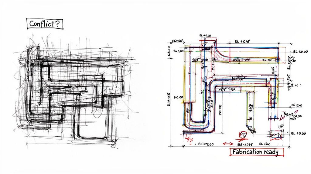
This process flow diagram shows what happens when you get the planning wrong.
This visual perfectly illustrates how one failure in planning inevitably creates conflicts that demand expensive rework. A disciplined project setup breaks that cycle.
A robust digital foundation is essential. Platforms like Autodesk Construction Cloud are designed to help with this collaboration, but they're only as good as the principles your team follows. To get into the nuts and bolts of collision analysis, check out our guide on clash detection in BIM. This initial investment in structure and communication makes scalable delivery and predictable outcomes possible.
The Anatomy of a High-Quality Ductwork Drawing
What separates a liability-ridden HVAC duct layout drawing from one an installer can build from confidently? It's a disciplined commitment to clarity, hierarchy, and buildability. A truly effective drawing is a communication tool first, leaving no room for assumptions on site.
A high-quality drawing anticipates the installer's questions and answers them visually. It moves beyond simple routing to become a precise instruction manual for fabrication and installation, directly protecting project margins by preventing RFIs and rework.
From Ambiguity to Actionable Detail
The journey from a vague concept to a buildable layout hinges on a few non-negotiable elements. These components transform a simple plan into a reliable source of truth. Poorly executed drawings are a primary source of budget overruns, while well-crafted MEP layouts are a cornerstone of operational consistency.
Here’s what every buildable ductwork drawing must include:
- Correct Duct Sizing Representation: Ducts must be drawn to their true dimensions, including insulation thickness. Representing an insulated 24×12 duct as a simple 24×12 rectangle is a classic mistake that causes immediate clashes.
- Consistent Elevation Strategy: Every piece of ductwork needs a clear elevation tag (e.g., bottom of duct, centerline) tied to the project datum. Random or missing elevation data is a direct path to on-site chaos.
- Clear Offsets and Transitions: All jogs, offsets, and size transitions must be explicitly dimensioned. An installer should never have to guess the angle of an offset or the length of a transition.
This level of detail is what prevents a layout that looks fine in plan from collapsing into a mess of conflicts when viewed in section.
The Power of Annotation and Hierarchy
Annotation isn't just labeling; it's creating a clear visual hierarchy. A cluttered drawing filled with overlapping text is just as useless as a drawing with no information. The goal is to provide all necessary data without creating visual noise.
A disciplined annotation strategy includes:
- Systematic Tagging: Every component, from VAV boxes to fire dampers, should be tagged consistently for accurate equipment schedules and seamless procurement.
- Legible Routing: Duct runs should be easy to follow, logically aligning with structural bays, lighting plans, and fire protection systems.
- Prioritized Information: Key information like main trunk line sizes and elevations should be prominent. Secondary details should be clear but not overpowering.
A great HVAC duct layout drawing tells a clear story. It guides the installer from the air handling unit to the final diffuser without confusion, ensuring the system is built exactly as designed.
Historically, getting this right was a challenge. Today, the residential ductwork design software market, valued at USD 296.5 million in 2022, has changed the game by enabling a level of precision that minimizes on-site errors. This shift is why studies now show simulated designs achieving 25% better energy performance than their manually drafted counterparts. You can explore this evolution by reviewing industry analysis from Grand View Research.
Good drawings prevent bad installations. The table below breaks down common mistakes versus best practices.
Key Elements of a Buildable Ductwork Drawing
| Drawing Element | Poor Practice (Causes RFIs) | Best Practice (Ensures Clarity) |
|---|---|---|
| Duct Sizing | Ducts drawn without insulation thickness. | Ducts modeled with full insulation dimensions. |
| Elevations | Inconsistent or missing elevation tags. | All ductwork tagged with consistent datum (BOD/CL). |
| Offsets & Transitions | Undimensioned jogs, forcing field measurements. | All offsets and transitions explicitly dimensioned. |
| Component Tagging | Generic or inconsistent equipment tags. | Unique, systematic tags for all equipment (VAVs, FDs). |
| Clash Coordination | Routing ignores structure, piping, and lighting. | Layout is fully coordinated against all other trades. |
| Annotation Clarity | Overlapping, unreadable text and leaders. | Clean, hierarchical annotations that prioritize key info. |
Ultimately, a high-quality HVAC duct layout drawing is the direct result of a coordination-first mindset, enabled by disciplined BIM workflows.
Using BIM for Predictable Ductwork Coordination
BIM is often pitched as the silver bullet for coordination, but any seasoned production team knows the truth: it’s just a tool. It only delivers results when backed by rigorous workflows. An uncoordinated BIM model is just a faster way to create the same old problems.
The key to predictable outcomes is the discipline you bring to it—turning 3D geometry into a reliable plan for fabrication and installation. This mindset shifts your team from constantly putting out fires to proactively preventing them. Instead of sifting through thousands of meaningless collisions, a mature HVAC BIM coordination process prioritizes and solves issues methodically.
Beyond the Clash Report: A Proactive Strategy
A classic mistake is treating clash detection as a pass/fail test run late in the game. By that point, rerouting a major duct run can trigger a costly chain reaction. Experienced teams front-load this process, baking coordination into every step of the design.
True clash prevention isn't a report; it's a strategy:
- Early Zone Definition: Before anyone models a single fitting, get in a room with the architect and agree on "no-fly zones" and dedicated MEP corridors.
- Systematic Clash Prioritization: Focus on the big stuff first, like major duct runs hitting primary structural steel, not minor conduit-on-pipe issues.
- Regular Overlay Meetings: Ditch endless email chains. Hold focused coordination sessions where issues are solved live in the model.
This approach stops problems before they start. It’s a discipline that pays off, especially for U.S. volume builders and architectural firms. Integrated duct layouts in BIM models have been shown to slash 20% off coordination clashes with other trades. For more on how these optimized designs are making an impact, check out the latest findings from Technavio's market analysis.
Coordinated Section Views: The Ultimate Validation Tool
Plan views lie. They can make a jam-packed ceiling plenum look wide open, hiding the vertical chaos. The only way to validate a complex hvac duct layout drawing is with coordinated section views.
Cutting sections through congested corridors, shaft spaces, and equipment rooms is non-negotiable. It’s the only way to visually confirm that the vertical hierarchy of all your systems—ducts, fire protection, sloped plumbing, and electrical trays—actually fits.
A layout that hasn't been validated with multiple, targeted section views is just a hypothesis waiting to be proven wrong by the first installer on site.
Aligning LOD with Project Phase
Another critical discipline is matching the Level of Development (LOD) to the project phase. Modeling with fabrication-level detail (LOD 350/400) during schematic design is a colossal waste of time. On the flip side, issuing ductwork drawings for construction with only schematic detail (LOD 200) is a recipe for an avalanche of RFIs.
A practical LOD strategy breaks down like this:
- Schematic Design (LOD 200): Ducts are modeled as simple volumes or single lines to reserve space and confirm primary routing paths.
- Design Development (LOD 300): The model includes accurately sized ducts, major fittings, and primary equipment with basic clearance zones.
- Construction Documents (LOD 350): The layout is fully detailed with insulation, access clearances, and supports modeled to confirm it’s buildable.
This phased approach prevents both wasted effort early on and critical information gaps later, transforming your BIM process into a reliable system for ensuring every MEP layout drawing is buildable and coordinated.
QA Processes That Prevent On-Site Surprises
A great drawing is only great if it’s been battle-tested before it hits the field. Mature production teams know that quality assurance (QA) isn’t a final checkbox; it's a risk mitigation strategy that protects margins by preventing last-minute surprises.
This goes beyond an automated clash report. True QA is about applying human intelligence and field experience to the model, catching the subtle issues that software misses. It's about looking at the HVAC duct layout drawing through the eyes of the person who has to fabricate and install it.
Moving Beyond Automated Clash Reports
Automated clash detection is a fantastic first pass, but it won’t tell you if a VAV box is impossible to service or if a run is too tight for flange connections.
This is where peer reviews and multi-trade overlay meetings are indispensable. A second set of eyes often catches inconsistencies the original modeler overlooked. More importantly, getting structural, plumbing, and fire protection teams in a room for a live overlay meeting allows for real-time problem-solving that prevents RFIs before they ever start.
Adopting an Installer's Mindset
The most effective QA happens when you review a model with an installer’s mindset. You have to ask the practical questions the person in the field would ask. This proactive approach is the cornerstone of reliable HVAC BIM coordination.
Think through these common failure points:
- Access Clearances: Is there enough physical space around that VAV box or fire damper for a technician to get their hands and tools in for service? Model the access zone, not just the equipment.
- Insulation and Flanges: Have you accounted for the full dimensions of an insulated duct, including space for flanges and connections? A 24×12 duct isn't 24×12 once it's wrapped and ready to hang.
- Support Locations: Does the layout allow for logical and structurally sound hanger locations? Routing a large duct without thinking about support options is a classic mistake.
- Fabrication Logic: Does the routing use standard, easily fabricated fittings where possible? Overly complex transitions add unnecessary cost and lead time.
A drawing that hasn't been reviewed for constructability is an expensive problem waiting to happen. The goal of QA is to find those problems in the controlled environment of the model, not the chaotic reality of the job site.
The Power of an Internal Checklist
The best firms codify this knowledge into an internal QA/QC checklist. This isn’t a generic to-do list; it’s a living document built from hard-won lessons on past projects. It's a repository of "never agains."
A strong checklist for ductwork drawings forces reviewers to verify compliance with project standards, from annotation styles to datum usage. It formalizes the process, turning tribal knowledge into a repeatable, scalable system. For excellent guidance on system design, you can also lean on standards like ACCA’s Manual T.
This rigorous QA process is what allows a firm to sell clarity and predictable delivery—not just hours. It ensures every MEP layout drawing is vetted for accuracy, coordination, and buildability.
Your Coordination-Ready Drawing Checklist
Throughout this guide, we've hammered home one core idea: a truly buildable HVAC duct layout drawing is the result of a disciplined system, not guesswork. It's about having a coordination-first mindset. This commitment prevents on-site chaos and protects your project margins.
Operational consistency is what separates mature production teams from everyone else. They get that clarity doesn't happen by accident; it's engineered into the workflow. This is the only way to create reliable shop drawings for construction that installers can trust.
From Theory to Practice
To help you turn these principles into action, we've put together a practical tool designed to reinforce this production maturity. We sell clarity and reliable delivery, not billable hours.
We invite you to download our HVAC Duct Layout Review Checklist.
Use this checklist to benchmark your own QA process and make sure your next set of ductwork drawings is genuinely ready for the field. It’s a concrete step toward catching common failures before they become expensive problems on-site, solidifying your reputation for getting it right the first time.
Frequently Asked Questions
We get a lot of questions from production teams trying to nail down their HVAC duct layout and coordination process. Here are a few of the most common ones.
What Is the Most Common Mistake in HVAC Duct Layout Drawings?
Hands down, the biggest mistake is drawing ducts in a 2D plan without a strictly enforced elevation strategy. Teams route ductwork where it seems to fit horizontally, forgetting about structural beams, fire sprinkler mains, and lighting fixtures fighting for the same space. This oversight leads to drawings that look fine on paper but are completely unbuildable. The result is major clashes, costly on-site rerouting, and a frustrated job site.
How Does LOD Affect Ductwork Drawings?
Level of Development (LOD) is everything for managing expectations. You have to match the level of detail to the project stage. At early stages (LOD 200), ducts are conceptual placeholders. By the time you hit LOD 300/350 for construction documents, that model needs to be precise: accurate dimensions, fittings, insulation, and required clearances. Modeling with too much detail too early burns time, while using a low LOD for construction is a recipe for RFIs. Aligning LOD with the project phase is key for effective HVAC BIM coordination.
Why Are Coordinated Section Views So Important?
Plan views can be incredibly deceptive. You might think a duct has a clear shot, but a section view tells the real story, often revealing a clash with a structural girder or sloped roof deck.
Coordinated section views that cut through congested areas are your ultimate validation tool. They are the single best way to visually confirm that the vertical stacking of all MEP systems—ducts, pipes, and conduit—actually works within the ceiling space. This simple step prevents major, expensive surprises during installation.
A disciplined, thoughtful approach to your MEP layout drawings is the surest way to protect your project margins and deliver predictable outcomes. At BIM Heroes, we’re focused on providing production systems and clarity, not just billable hours. See how we help teams build better by visiting us at https://www.bimheroes.com.