A metal stud frame partition wall looks simple in Revit. But the difference between a model that saves coordination time and one that creates RFIs often comes down to five or six details that never make it into the model. Here's what actually matters to the contractor building it. A massive gap often exists between a design-intent model and one that’s actually ready for construction, especially when it comes to the metal stud frame. This post is a practical translation guide to bridge that gap, ensuring your BIM workflows deliver clarity, predictability, and margin protection.
Why Metal Stud Frame Models Often Fall Short
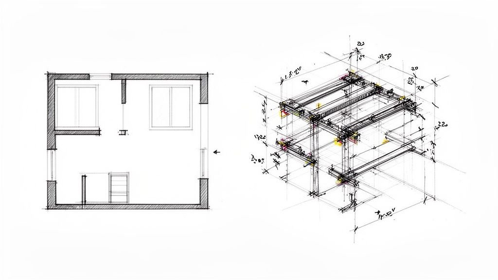
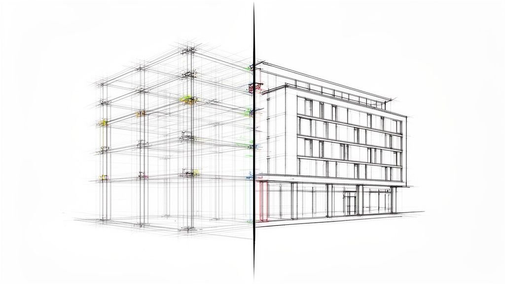
Your architectural model often shows a metal stud frame wall as a simple, generic partition, usually at a Level of Development (LOD) 200–250. On screen, the wall looks complete. But in reality, it’s just a placeholder. Critical details like stud size, gauge, and spacing exist only as background parameters, not as explicitly modeled geometry. This is the core of the problem—the model lacks the DNA a contractor needs to build from.
Projects that issue partition layouts without this level of detail generate avoidable RFIs during framing, disrupting production and hurting the bottom line. What an architect needs for design visualization is worlds apart from what a drywall subcontractor needs for installation. They’re looking for specific, actionable data to lay out the work, order materials, and coordinate with other trades on site.
When the model only provides a basic wall type, it forces the contractor to stop work and ask questions that should have been answered weeks or months earlier. These gaps typically revolve around a few key details:
- Exact Stud Spacing: Is it 16" or 24" on-center? Where does that spacing change to support heavy finishes or frame out openings?
- Track and Head Details: What type of track is needed at the base and head of the wall? More importantly, is a deflection head detail required to handle structural movement?
- Connections to Structure: How does the wall tie into the primary structural steel or concrete slab? This is one of the most common sources of RFIs from the field.
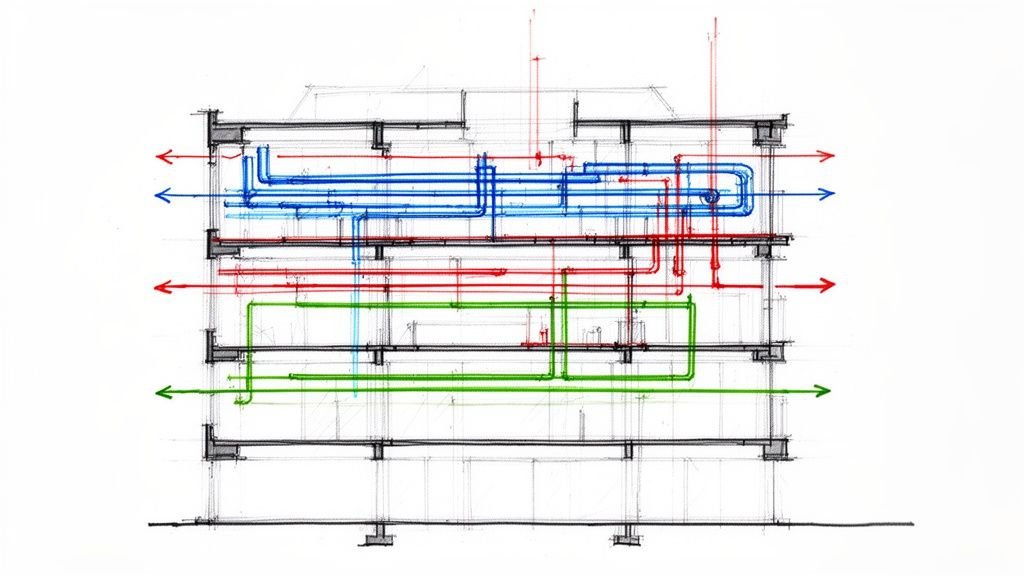
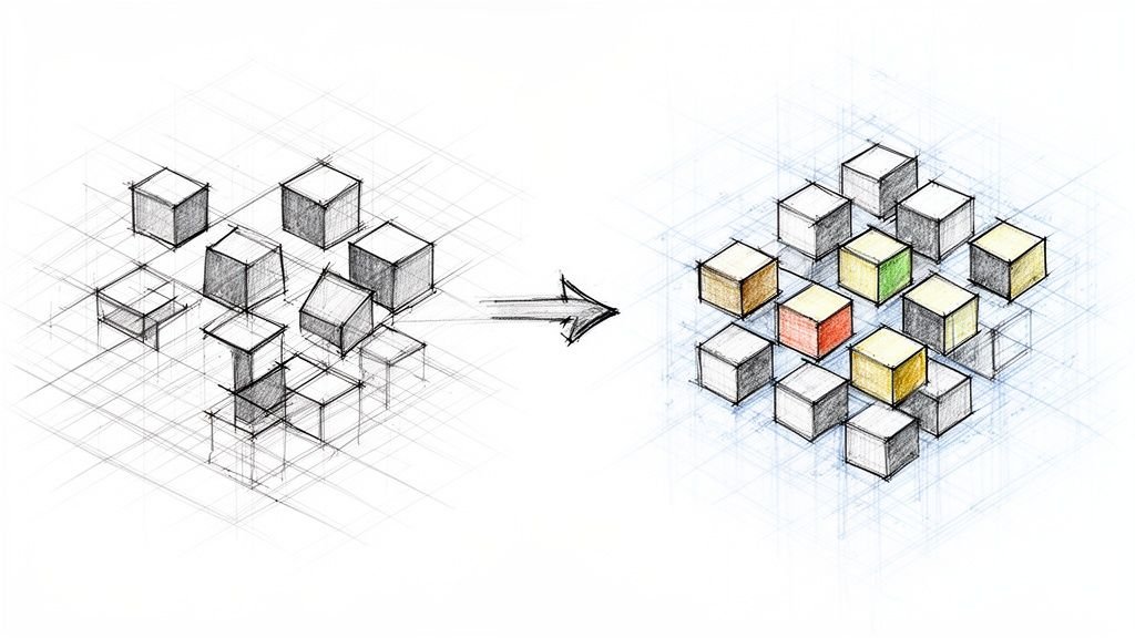
This flowchart shows the direct line from an incomplete model to project delays.
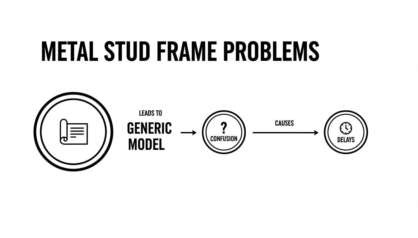
The path is clear: a generic model creates confusion, and that confusion inevitably leads to costly delays and rework. Every RFI is a pause in production, an opportunity for error, and a hit to the project’s margin. The goal of a mature BIM workflow is to break this cycle by embedding construction-level intelligence directly into the model, moving beyond simple representation to proactive, buildable design that ensures operational consistency.
The 6 Things a Metal Stud Frame Layout Must Communicate
To prevent a flood of RFIs and keep your project on schedule, a metal stud frame layout needs to do more than just reference a wall type schedule. It has to provide clear, buildable instructions. The difference between a job that runs smoothly and one bogged down by questions often comes down to these six critical details. These aren't just suggestions; they are the essential instructions a drywall contractor needs to get the work done right the first time.
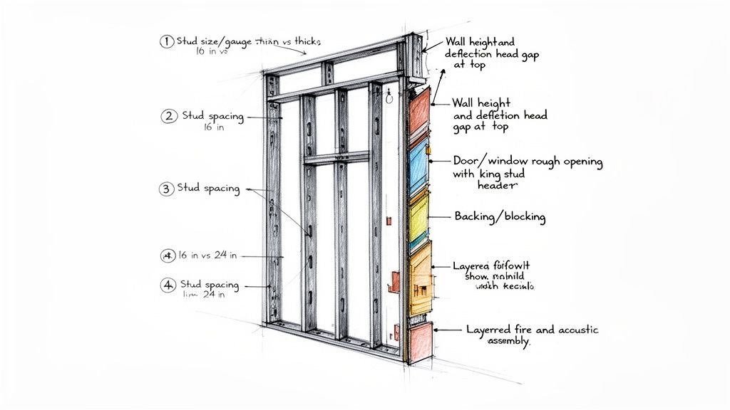
1. Stud size and gauge
Simply labeling a partition as a "3-5/8 inch wall" isn’t enough. The contractor needs the full track and stud designation, which includes the material's thickness, or gauge. A simple non-load-bearing partition might use a lighter 20-gauge stud, but a load-bearing metal stud frame system, or one in a high-traffic area, will need something heavier. Your specs must be clear, as this decision affects material orders, cost, and structural integrity. Any assumption here is a recipe for a failed inspection or a costly change order.
2. Stud spacing
The classic "16 inches on-center" note is a starting point, not the final word. A truly buildable metal stud framing layout shows exactly where and why that spacing needs to change. Your model must explicitly define every variation.
Think about common conditions:
- Around Openings: Standard spacing is always interrupted at doors and windows.
- Heavy Wall Finishes: Walls with heavy tile or stone often need tighter stud spacing—like 12" O.C.—for adequate support.
- Braced Conditions: Any areas requiring structural sheathing will have their layout dictated by panel dimensions.
When you don't call out these changes, you're forcing the framing contractor to guess. That’s a risk no project schedule or budget can afford.
3. Wall height and deflection head
In commercial projects, the metal stud frame must accommodate structural movement at the top track. This is handled with a deflection head detail. It isn't an optional add-on; it's a fundamental part of how the system performs. Forgetting to specify it is one of the most common—and disruptive—RFIs. The drawings must clearly show the type of deflection track, the required gap, and the specific fastening requirements. This detail is critical for preventing drywall cracks and buckled studs. For a deeper look at how our teams handle cross-discipline issues, check out our thoughts on MEP coordination.
4. Door and window rough openings
A generic opening in a Revit model tells the field crew almost nothing. A buildable layout must detail the exact members that form every rough opening: king studs, cripple studs, and the header type. These are frequently missing from generic partition models and create field confusion. Modeling these individual components, even at a basic LOD, eliminates guesswork and ensures the layout accounts for the extra material needed. This is a classic failure point for design-intent models.
5. Backing and blocking
Contractors cannot assume where backing goes—it must be shown. If something is getting mounted to a wall—a grab bar, cabinets, a TV mount, or wall-mounted equipment—it needs solid backing inside the stud cavity. This is a classic coordination failure that is 100% avoidable with a disciplined QA process. The documentation must clearly state the exact location, material, and thickness. Modeling backing in Revit is the best way to handle this, as it allows for precise placement and clash detection against MEP elements.
6. Fire- and acoustic-rated assemblies
A rated wall is a complete system. When a UL assembly is specified, every component of that metal stud frame wall is dictated by the rating. This is a life-safety requirement where zero deviation is acceptable. The model and drawings must explicitly identify the UL assembly number, required stud gauge, insulation fill requirements, and sealant details. Treating a rated wall like any other partition during modeling is a massive risk that can lead to failed inspections and expensive rework.
LOD Guidance for Metal Stud Frame in Revit
Figuring out how much detail to put into your metal stud frame models is a constant balance. The goal is to provide the right information at the right time, protecting your margins and making the project predictable. This isn’t about chasing the highest LOD; it's about decision checkpoints and production maturity.
LOD 200: The Design-Intent Model
At this early stage, a wall is a generic placeholder.
- What's Included: A simple partition with wall type defined and stud size as a parameter.
- Typical Use Case: Appropriate for early design and schematic coordination. Issuing this for construction is a surefire way to get buried in RFIs.
LOD 300: The Permit and Construction Document Model
This is the minimum for permit-ready construction documents. The model starts looking less like a concept and more like buildable instructions.
- What's Included: Stud spacing is represented, openings are modeled, rated assemblies are noted, and the deflection head is shown.
- Typical Use Case: Submitted for permits and used by contractors for bidding. It answers the most common field questions.
LOD 350: The Fabrication and Full Coordination Model
This is where the model becomes a digital twin, required for shop drawings and design-build delivery. The model stops being a drawing and becomes a set of instructions.
- What's Included: A full metal stud frame layout with connections, backing locations, hardware coordination, and interface with adjacent structure. Every stud, track, and piece of backing is accounted for. This level has become essential as the light-gauge steel framing market—valued at over $36 billion in 2022—continues to grow. You can explore the full market research on light-gauge steel framing to see why efficiency is driving adoption.
- Typical Use Case: A must-have for design-build, prefabrication, and any job focused on minimizing field labor and preventing RFIs. This is where our coordination work for contractors and design-build clients typically sits. For more on this, see our guide on BIM Level of Detail.
What a Good Metal Stud Frame Shop Drawing Looks Like
There’s a huge leap from a CD partition schedule to an actual framing shop drawing. A framing shop drawing isn’t just a cleaned-up version of the plan; it’s an exact instruction manual for the installer. This is where the translation from design intent to buildable instructions starts, and where a disciplined process can prevent margin erosion.
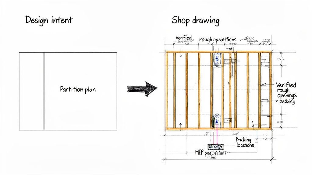
A framing shop drawing adds the following over a standard partition plan:
- Stud layout drawn to scale, not just noted. The shop drawing shows every single stud—king studs, jack studs, cripples, and all headers.
- Verified rough opening dimensions matched to door and hardware schedules. It cross-references plans with schedules to confirm exact sizes, preventing expensive misfits.
- Backing shown in both plan and elevation. Vague notes are replaced with explicit details for grab bars, cabinets, or wall-mounted equipment, with precise dimensions and material callouts.
- Coordination with MEP rough-in: switches, outlets, pipe penetrations. This ensures studs don’t land where a plumber needs to run a pipe, preventing a ton of potential RFIs.
- Rated assembly UL numbers clearly called out per wall type. Assumptions die here, replaced with verified, buildable instructions.
The U.S. steel framing market, reliant on the precision of the light gauge metal framing, demonstrates the value of this process. This meticulous shop drawing stage is what gives the system its resilience and adaptability in the field. You can learn more about the steel studs market growth and its impact.
How BIM Heroes Handles Metal Stud Frame Coordination
This is what we do. We don’t sell hours; we sell clarity, systems, and reliable delivery. We model metal stud frame systems at the LOD the project requires—from CD-level partitions to LOD 350 coordination models for design-build teams. This isn’t aspirational; it’s about production maturity.
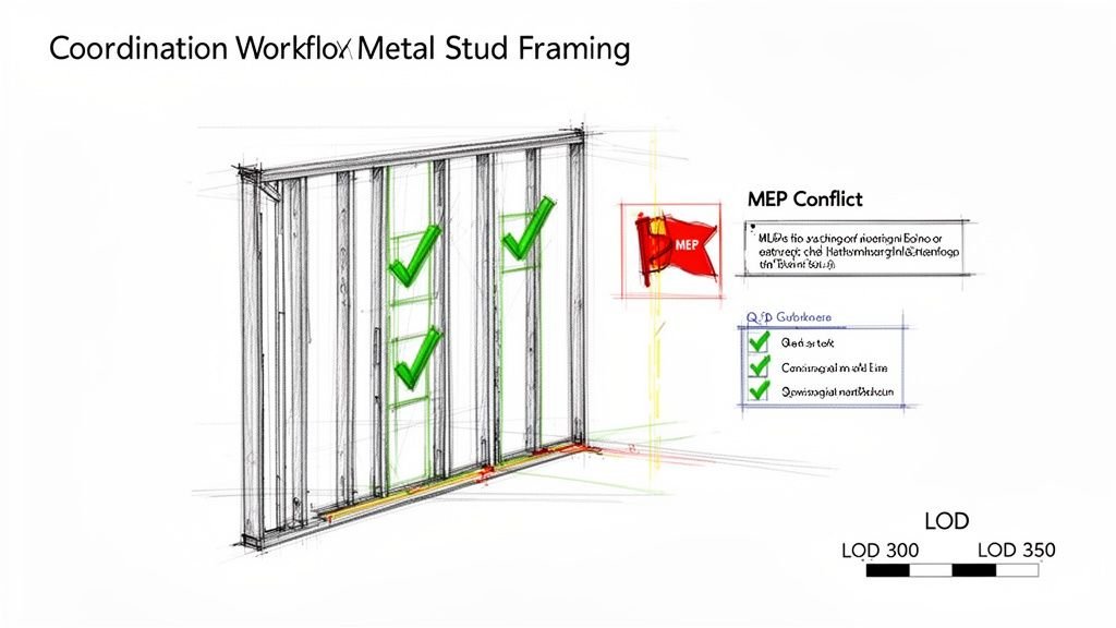
Our production team flags coordination issues before they reach the field. We hunt for the kinds of conflicts that derail projects, focusing on:
- MEP conflicts: Clashes between framing and ductwork, conduit, or plumbing lines.
- Missing blocking: Ensuring every fixture and piece of wall-mounted equipment has the correct support specified.
- Unresolved rated assemblies: Making sure every component matches the specified UL design.
We work directly in your project’s Revit environment, integrating with architectural, structural, and MEP models. Our scalable delivery pods become an extension of your team. Clients receive clean, contractor-ready documentation—not a model that still requires interpretation on site. We transform design intent into actionable shop drawings, which you can learn more about in our guide on what shop drawings mean for your project's success. Our process gives your team exactly what it needs: a reliable path from a digital model to a built reality.
Your Path To Predictable Metal Stud Frame Layouts
A metal stud frame system that isn't properly coordinated in the model creates cost and schedule problems downstream. The gap between a typical architectural model and what a contractor can actually build from is a massive source of avoidable RFIs, on-site delays, and shrinking margins. By embedding the six essential details—from stud gauge to backing locations—into your BIM workflow early on, you give contractors what they need to build without guessing.
This detailed approach is your blueprint for protecting profit margins. Every question answered in the model is an RFI that never gets written and a delay that never happens. It is the most direct path to a predictable outcome. For many firms, building this capability in-house is a challenge. It takes disciplined templates, tough QA processes, and a deep understanding of what happens on site. If you're leveraging techniques like scan-to-BIM, this level of detail is even more critical for renovation projects.
Want a checklist of everything your metal stud frame layouts should include before issuing for permit? Download our free Revit Framing Coordination Checklist.
At BIM Heroes, we transform design intent into buildable, coordinated models. Our production-focused approach ensures every detail, from stud spacing to rated assemblies, is accounted for, protecting your margins and delivering clarity. Learn how we can help your next project at https://www.bimheroes.com.