You can’t treat modular construction design like a conventional site-built project in BIM. That single mistake is why so many modular projects go off the rails. To succeed, you have to make a fundamental shift: you’re designing for manufacturing, not just for visualization. This means embedding factory constraints, transportation limits, and assembly tolerances into your model from day one.
Why Most Modular BIM Designs Fail
The promise of modular construction—speed, cost certainty, quality control—evaporates when design teams miss one critical truth. You are designing a product for a factory floor, not just a building for a construction site.
Many modular projects stumble, not because the concept is flawed, but because the BIM for modular design is treated like a traditional documentation tool. It becomes a pretty picture instead of what it needs to be: a precise set of manufacturing instructions. This disconnect between architectural intent and factory reality is where margins get crushed and schedules fall apart.
We’ve seen modular projects stabilize once teams lock module logic early and stop redesigning around factory constraints. The failure point is almost always a design assumption that looks great on screen but simply doesn't work on the production line or during final assembly.
The Disconnect Between Design and Production
The real challenge in designing for modular construction isn't structural engineering; it's a precision and coordination challenge. A BIM model might look perfect, but if it doesn't account for manufacturing tolerances, transportation limits, and crane sequencing, it’s functionally useless for fabrication.
Teams new to modular fall into the same predictable traps that create chaos downstream. These aren't rookie mistakes. They're the logical result of applying traditional site-built thinking to a manufacturing process.
You'll know your workflow is failing if you see these common pain points:
- Unnecessary Complexity: Models are bogged down with excessive detail (improper LOD progression) that adds zero value for the fabricator but kills model performance.
- Late Design Changes: A seemingly minor change, like nudging a window, breaks the standardized logic of dozens of modules, triggering a cascade of rework that destroys margin protection.
- Misaligned MEP Zones: Inter-module connections for mechanical, electrical, and plumbing systems are poorly defined, setting you up for major clashes and costly delays during on-site assembly.
- Vague Connection Details: The model lacks the specific tolerances and details needed for module-to-module and module-to-foundation connections, leading to preventable RFIs and guesswork.
The real measure of a modular BIM model isn't its visual fidelity. It's whether it can be used to generate clear, unambiguous shop drawings that prevent RFIs and support an efficient factory workflow.
Ultimately, successful prefabrication BIM workflows demand a completely different mindset. The model must become the single source of truth for a distributed production system, reflecting factory capabilities just as much as it reflects the architectural vision. Making that mental shift is the first and most critical step toward delivering predictability and operational consistency.
Thinking Like a Manufacturer From Day One
Success in modular construction design starts with approaching the project like a manufacturer, not just an architect. This isn't a box you check later in the process; it's a mindset that must drive every decision in the BIM model from the very first click. The most profitable and predictable modular jobs are always the ones where the team thinks in terms of production maturity and systems, not just construction sites.
This means leading with the constraints. What’s the biggest module the factory can build? What are the legal dimensions for road transport? What’s the crane’s lift capacity and reach on site? These aren’t annoying details to figure out later—they are the hard boundaries that define the entire design.
The moment these constraints become creative guardrails instead of obstacles, you start designing for production and protecting your margins.

Defining the Unshakeable Foundation
Before you model a detailed wall assembly, three things must be set in stone: the module boundaries, the structural grid, and the datum levels. Think of these as the project's constitution. Changing them later unleashes a level of chaos and rework that completely wipes out the business case for going modular in the first place.
These early decision checkpoints create the consistency needed for scalable delivery pods.
- Early Module Definition: Nail down the precise volumetric box for each module type. This isn't just about length, width, and height; it includes clear, modeled zones for all the inter-module connections. Getting this right prevents the painful redesign needed when a concept can't be split into shippable units.
- Standardized Structural Grids: A consistent, repeatable grid is the backbone of efficient fabrication. It simplifies engineering, standardizes component procurement, and makes the factory assembly line run smoothly. Any deviation from the grid should require a formal sign-off.
- Fixed Datum Levels: Lock in absolute floor-to-floor heights and other critical vertical datums. These fixed reference points guarantee that modules built in different batches will line up perfectly when they arrive on site.
A disciplined BIM for modular design process never leaves module breaks to chance. It models the 'air gaps' and connection zones between units with the same precision as the modules themselves. This is how you prevent catastrophic assembly failures on site.
From CAD Logic to BIM Production Systems
This manufacturing-first approach is about more than just a CAD-to-BIM evolution. It demands a system where the "I" in BIM (Information) is structured specifically for a production workflow. Your model has to answer questions for the factory floor, not just the architectural review board.
For example, your model needs to clearly show transportation and lifting points and contain accurate weight calculations to inform crane selection. It also means getting smart about your supply chain; it's worth exploring proven procurement cost reduction strategies that can make a huge difference to a modular project's bottom line.
This proactive, constraint-based design is becoming more important as the market expands. According to the Modular Building Institute's industry analysis page, the sector continues to show robust growth, rewarding teams that deliver precise, factory-ready BIM models.
Ultimately, designing for modular construction is less about limitless architectural expression and more about finding elegant solutions within a fixed set of rules. By defining these rules early and enforcing them with disciplined prefabrication BIM workflows, you turn the design process from a source of risk into a powerful engine for predictable delivery.
Building Disciplined BIM Workflows for Prefabrication
A successful modular BIM workflow is built on data integrity, template discipline, and providing crystal-clear instructions for fabrication. Shifting from a site-built mindset to a manufacturing one demands a disciplined approach to how you structure your entire BIM process.
Without this discipline, teams create models that look great in a render but are useless on the factory floor. The result? A flood of RFIs, production grinds to a halt, and profits get eaten away. The secret is to build a workflow that puts the fabricator first.
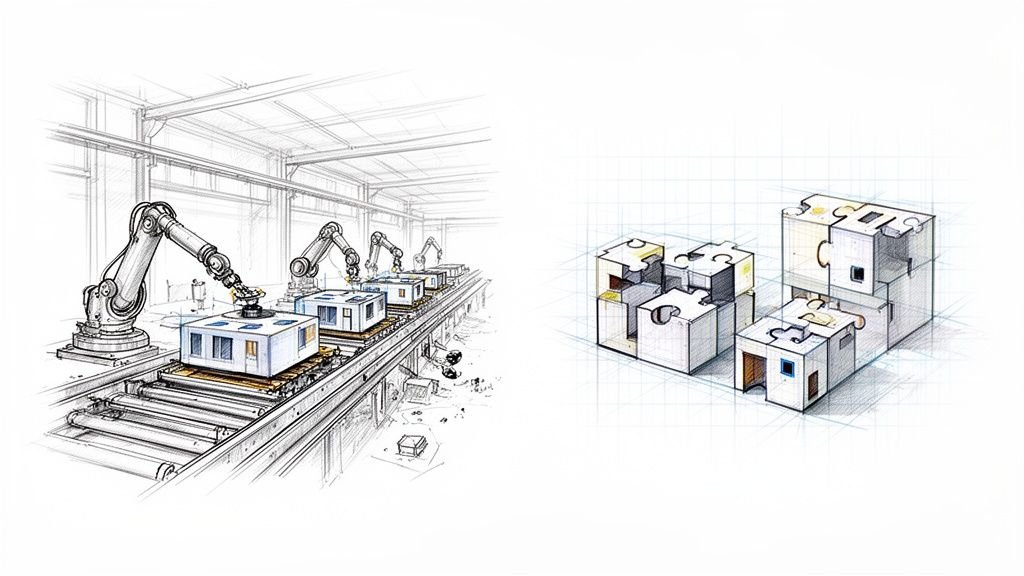
The diagram below shows a simplified, disciplined path from the initial grid setup all the way to transport-ready modules.

As you can see, foundational decisions like the structural grid directly constrain the module design, which then has to respect transport limitations before it ever sees the construction site. It's a chain of constraints you have to design for from day one.
Traditional vs. Modular BIM Workflow Priorities
The shift from traditional to modular isn't just about changing software settings; it's a fundamental change in priorities. You move from designing a unique, one-off building to designing a repeatable, manufacturable product. This table breaks down the key differences in focus.
| Design Aspect | Traditional Site-Built BIM Focus | Modular Construction BIM Focus |
|---|---|---|
| Model Goal | Representing final design intent for on-site interpretation. | Providing precise fabrication instructions for the factory. |
| LOD Progression | Gradual, often uniform development across the model. | Strategic, high-LOD focus on interfaces and connections early on. |
| Core Unit | The entire building as a single, unique entity. | The repeatable module as a standardized, productized unit. |
| Coordination | On-site clash detection and resolution. | "Clash prevention" through pre-vetted, standardized module designs. |
| Tolerances | Generous, assuming on-site adjustments can be made. | Extremely tight, with no room for error between factory and site. |
| Data Management | Focused on documentation and visualization. | Focused on data for procurement, logistics, and assembly sequencing. |
Trying to force a traditional BIM process onto a modular project is a recipe for budget overruns and schedule delays.
The Critical Role of LOD Progression
One of the most common—and expensive—mistakes we see in BIM for modular design is a chaotic approach to Level of Development (LOD). Teams often jump straight to LOD 400 detail across the entire model, creating massive, sluggish models bloated with data that adds zero value to the manufacturing process.
A disciplined LOD progression is essential.
- LOD 200 (Schematic): Set the rules. Define module volumes, the structural grid, and primary MEP zones.
- LOD 300 (Design Development): Develop specific assemblies within the module prototypes. Model primary structural members, MEP mains, and major architectural elements.
- LOD 350/400 (Fabrication Detail): Apply high detail only where it matters most—at the interface points between modules. This includes precise modeling of connections, hookups, and weatherproofing details with exact tolerances.
This staggered approach keeps the model lean and ensures your team’s effort is focused on the areas with the highest risk of coordination meltdowns.
The goal isn't to model every screw. It's to provide just enough information, at just the right time, for the factory to build and the site team to assemble without a single question.
Managing Repeatable Units and Interface Zones
In modular construction, you're designing a series of repeatable products. Managing these standard units effectively is key to efficiency. Your BIM strategy must ensure that a change to a single repeatable unit—like a standard bathroom pod—propagates flawlessly across the entire project. This requires serious template discipline.
Just as important are the interface zones—the negative space between the modules. These zones must be modeled with extreme precision. This is where trades hook up their systems and where structural loads are transferred. Modeling these interface zones as distinct elements in your BIM coordination process is non-negotiable.
Aligning BIM with Market Demand
Focusing your BIM efforts also means understanding where the market is headed. As shown by reports from sources like Grand View Research, the demand for multi-story residential and commercial buildings is driving much of the growth. The highest-value BIM work will be in creating repeatable unit plans and highly coordinated MEP systems.
By building disciplined workflows, you align your design process with the realities of manufacturing and the demands of the market. To see how these principles fit into a larger production sequence, check out our detailed guide on the complete prefabrication workflow explained.
Solving Coordination for Flawless Assembly
In traditional construction, a one-inch misalignment is an annoyance fixed with fieldwork. In modular construction design, that same error can bring the entire assembly process to a grinding halt, jeopardizing crane time, labor costs, and project timelines. You completely lose the forgiveness of a traditional job site.
Every connection point—structural, mechanical, electrical, and plumbing—has to align perfectly as modules are craned into place. This demands a much more rigorous approach to coordination within the BIM model, one that truly anticipates the realities of the factory and the final assembly.
A disciplined coordination process treats the model as the absolute single source of truth for every trade, from the factory floor to the final installation.
Beyond Standard Clash Detection
Standard clash detection, which focuses on simple hard clashes like a pipe hitting a beam, just doesn't cut it for modular workflows. Your coordination strategy has to evolve to account for a whole new set of risks.
A mature modular construction BIM workflow includes checks for:
- Manufacturing Tolerances: Are you leaving enough space for the actual fabrication variance of a component, not just its perfect modeled dimension?
- Transportation Clearances: Does the model account for the temporary bracing or wrapping required for shipping?
- Assembly Sequencing: Does a chosen MEP connection point become inaccessible once the module next to it is installed? The model has to be checked against the planned install sequence.
- Service Access: Is there enough clearance around connection points for a technician to get their hands and tools in there to make the connection?
This advanced review is less about finding errors and more about validating the manufacturing and assembly plan itself. Our in-depth guide to clash detection in BIM provides a solid foundation for these more advanced checks.
The Master Coordination Model as the Single Source of Truth
The only way to manage this complexity is with a master coordination model. This federated model aggregates the latest models from all disciplines and becomes the definitive source of truth that governs every decision.
In modular design, the master coordination model isn't just a review tool; it's the virtual assembly floor where the entire building is constructed digitally before a single component is fabricated. This process is what protects margins and ensures predictability.
This central model is where you rigorously police the interface zones between modules. A common point of failure is misaligned MEP zones, which are invisible in isolated models but become glaringly obvious in a properly managed coordination model, preventing expensive on-site modifications. For complex projects, leveraging specialized modular assembly services can be key to overcoming these challenges.
Preventing RFIs and Protecting Predictability
Ultimately, this intense, front-loaded coordination process is all about RFI prevention. Every clash resolved in the model is one less question from the factory and one less potential delay on site. It shifts problem-solving from the expensive, high-pressure environment of the construction site to the controlled, low-cost digital environment.
This proactive approach has a direct and measurable impact on the project's bottom line. It protects margins by eliminating rework, slashes the risk of schedule overruns, and delivers the operational consistency that is the entire promise of modular construction. When your BIM for modular design prioritizes flawless assembly, you move from hoping for a good outcome to building a system that reliably produces one.
Creating Factory-Ready Documentation from Your Model
A perfectly coordinated BIM model is only half the battle. If that digital precision doesn’t translate into crystal-clear documentation for the factory floor, the production line will grind to a halt. In modular construction design, the final link is a set of drawings built for a manufacturing environment—not a traditional job site.
Standard architectural drawings often leave room for interpretation. In prefabrication, that’s a recipe for disaster. A single ambiguous detail can stop a production line, trigger a flood of RFIs, and cause costly errors that get multiplied across every single module. The goal is to produce documentation that speaks the fabricator’s language, leaving zero room for guesswork.
From Architectural Plans to Manufacturing Instructions
The deliverables for a modular project look fundamentally different from a conventional drawing set. They are filtered, annotated, and structured to answer the specific questions a factory team will have.
Key documentation types typically include:
- Individual Module Drawings: Each drawing details a single module in isolation, showing complete dimensions, component callouts, and assembly steps.
- Assembly Diagrams: These show how individual modules connect, focusing obsessively on the interface zones, structural connections, and MEP hookups.
- Connection Details: These are highly magnified views of every unique connection condition, including tolerances, fastener specs, and sequencing notes.
- Schedules and Cut Lists: Direct data exports from the model that drive procurement and fabrication.
Getting this level of detail right is a core part of a successful prefabrication BIM workflow. You can dive deeper into this topic in our guide on creating effective shop drawings for construction.
Here’s the litmus test for your documentation: Can a fabricator build an entire module using only the drawings you provided, without asking a single question? If the answer is no, the documentation has failed.
The Growing Need for Production-Ready BIM
Mastering this documentation process is becoming more critical as the modular market explodes. Market data, like that found in modular construction market reports, projects significant global growth. This isn't a niche market anymore; it represents a massive wave of projects where production-ready BIM for modular design is the only way to succeed.
When you treat your documentation as a critical manufacturing tool, you prevent RFIs before they happen, protect your margins, and ensure the design intent from your model is perfectly executed on the factory floor. This is how you achieve the operational consistency that modular construction promises.
Building a Predictable Modular Delivery System
Making the leap to a successful modular practice is about more than adopting new software—it demands a different way of operating. True scalability in modular construction design comes from building a predictable delivery engine that locks in consistency and protects your margins. This is the shift from selling hours to selling clarity, systems, and reliable outcomes.
This operational change is built on a foundation of relentless standardization and production maturity. It’s about creating a system that stamps out variables and maximizes repeatability.
Establishing Production Pods and QA Checkpoints
A powerful way to bake in consistency is to organize your teams into small, focused "delivery pods." Each pod runs on a standardized workflow, uses the same disciplined templates, and sticks to a common set of QA processes. This structure prevents the "process drift" that so often trips up firms as they grow.
To make these pods effective, you have to establish clear decision checkpoints—formal gates where key stakeholders must sign off before anyone moves forward.
- Checkpoint 1: Module Logic Lock. The grid, module dimensions, and transport envelopes are finalized. No more changes without a formal review.
- Checkpoint 2: Interface Zone Approval. All module-to-module connections for structure and MEP are fully modeled and approved.
- Checkpoint 3: Fabrication Data Freeze. The model is locked down, and shop drawings are generated. From this point on, only critical changes are considered.
These checkpoints are your primary defense against the scope creep and late-stage design changes that destroy profitability.
The core principle is simple: make decisions early and stick to them. A robust system with clear decision checkpoints forces the difficult conversations to happen when they are cheap to solve—in the digital model, not on the assembly line.
This systemized approach transforms BIM for modular design from an art into a science. It builds confidence with your clients and predictability for your business, turning modular delivery from a constant fire drill into a smooth, well-oiled machine.
Ready to build more predictability into your process? Our Modular BIM Design Checklist provides a practical framework for implementing these principles, helping you establish the template discipline and decision checkpoints needed for scalable delivery.
At BIM Heroes, we help firms build the production systems and disciplined workflows needed to make modular delivery predictable and profitable. If you're ready to get past the frustration and build a system that scales, we're here to bring the clarity and support you need.