In custom metal panel systems, accuracy isn’t a goal—it’s the foundation of margin protection. A single millimeter of deviation in the shop can trigger a cascade of failures on site: misaligned reveals, panels that won’t seat, and clashes with the backup structure that halt installation and destroy schedules.
Traditional 2D workflows leave too much to interpretation. They force fabricators and installers to bridge the gap between design intent and physical reality, creating opportunities for the very errors that erode profitability. This guide is a playbook for eliminating that ambiguity. The core message is simple: in panel fabrication, accuracy isn’t achieved by detailing harder—it’s achieved by modeling smarter with BIM.
Where Panel Projects Fail (and Why 2D Workflows are the Cause)
For architects, façade consultants, and fabricators, project success hinges on flawless execution. A small error in a shop drawing snowballs into field rework, endless RFIs, and busted budgets. This isn’t an inconvenience; it’s a direct hit to operational consistency and your reputation.
The root cause is almost always the same: fragmented data and interpretation gaps inherent in 2D processes. When shop drawings are just a collection of disconnected lines on a screen, you invite failure.
The Real Failure Points in Custom Metal Panel Projects
We’re not talking about generic BIM benefits. We're talking about preventing specific, costly mistakes grounded in fabrication and installation reality:
- Inconsistent Panel Sizes: Manual dimensioning across dozens of sheets leads to typos and drift, resulting in panels that are cut incorrectly.
- Misaligned Reveals: Without a governing logic, joint widths vary across an elevation, creating a visibly poor-quality installation.
- Incorrect Datum References: When the panel layout isn’t locked to the primary structural grid, mounting hardware misses its connection points.
- Unresolved Corner Conditions: 2D details often fail to communicate the precise geometry of complex corners, leaving fabricators to guess.
- Clashes with Backup Structure: Panels are fabricated and shipped, only for installers to discover they interfere with steel, insulation, or conduits.
- Unclear Fastener Logic: Ambiguous details lead to incorrect fastener placement, compromising both aesthetics and performance.
The greatest weakness of a 2D workflow is that it cannot enforce rules. It relies on people to be perfect under pressure—a recipe for margin erosion.
This guide explains how to use Building Information Modeling (BIM) as a precision control system to eliminate these failure points before they ever reach the shop floor. It’s about building a system that delivers predictability and protects your bottom line.
BIM as a Precision Control System, Not Just a Coordination Tool
Moving past 2D requires a shift in mindset. For complex panel fabrication, BIM is not just a 3D visualization tool; it’s a production control system. The model becomes the single, indisputable source of truth, locking in geometry and enforcing design intent from the initial layout to the final fabrication file.
This isn’t about making a prettier picture. It’s about building a digital machine that guarantees the accuracy of your metal panel shop drawings.
Controlling Panelization Logic with Parametric Families
The power of BIM for façade detailing lies in parametric panel families. These aren’t static 3D blocks; they are intelligent components with built-in rules.
For example, a rule can be set that every panel joint must be exactly ½-inch. As the façade is populated with these families, the model automatically enforces this dimension everywhere. This simple constraint eliminates inconsistent reveals and ensures the panelization logic is maintained across thousands of unique components without manual oversight. It makes consistency the default.
Maintaining Consistent Joints with Rule-Based Layouts
In a 2D workflow, verifying joint consistency across an entire project is a tedious manual task prone to error. In BIM, consistency is automated.
By embedding the joint dimension directly into the panel family, the rule is applied globally. If a design change requires adjusting the joint width from ½-inch to ¾-inch, that change is made once in the family definition and instantly propagated across the entire model. Every panel updates automatically, ensuring uniformity without redrawing a single line. This is a level of control that 2D simply cannot offer.
Validating Tolerances Before a Single Panel is Cut
One of the most expensive field errors is discovering a clash during installation. A BIM workflow prevents this through proactive clash detection. Before fabrication begins, the façade model is federated with the structural and MEP models. This digital "test fit" identifies every location where a panel interferes with a steel beam, a conduit, or insulation.
A clash found in the model is a five-minute coordination task. A clash found on site is a five-day work stoppage that requires rework, RFIs, and a change order.
This process transforms quality control from a reactive, post-fabrication problem into a proactive, pre-production checkpoint.
How BIM Resolves Common Failure Points
The table below contrasts the reactive nature of 2D with the proactive control of a BIM-driven system for custom metal panel detailing.
| Fabrication Task | Risk in 2D Workflow | Resolution in BIM Workflow |
|---|---|---|
| Panel Sizing & Layout | Inconsistent panel sizes and misaligned reveals from manual errors. | Parametric panel families and rule-based layouts enforce uniformity. |
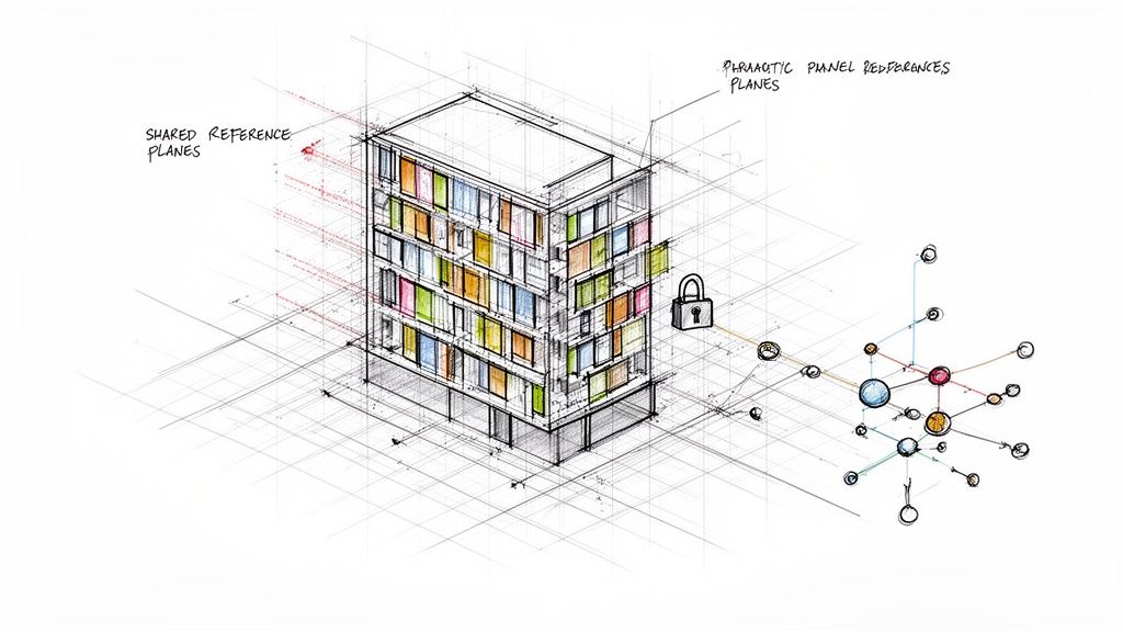
| Datum & Grid Alignment | Panel layout drifts from the structural grid, causing fastener misses. | Shared reference planes lock the façade to the structure, ensuring perfect alignment. |
| Tolerance Validation | Clashes with backup structures are discovered during costly installation. | Digital clash detection identifies and resolves interferences before fabrication. |
| Complex Geometries | Corners, soffits, and terminations are ambiguous and prone to misinterpretation. | The 3D model provides absolute geometric clarity, eliminating guesswork. |
| RFI Generation | Disconnected drawings create interpretation gaps, leading to constant RFIs. | The model serves as the single source of truth, answering questions before they are asked. |
This systematic approach to shop drawing accuracy delivers the operational consistency needed to protect margins and deliver complex projects with confidence. We don’t sell hours; we sell clarity, systems, and reliable delivery.
Bridging the Digital-to-Physical Divide
A fully coordinated BIM model is more than a design document; it’s a direct instruction set for fabrication machinery. This CAD-to-CAM workflow closes the last and most critical gap where errors occur: manual data entry at the CNC machine.
Instead of an operator interpreting a 2D drawing, the high-LOD model exports machine-readable files directly. This seamless digital handoff ensures the machine cuts, bends, and punches with the exact geometry validated in the model. There is no room for human error.
What you model is what gets fabricated. The BIM model becomes an active component of the manufacturing process, not just a precursor to it.
The Importance of Template Discipline and QA Checkpoints
Making this connection seamless requires production maturity. It’s about establishing rigorous template discipline and decision checkpoints throughout the BIM workflow. Fabrication-ready panel families must be data-rich, containing more than just geometry:
- Material Specifications (type, thickness, finish code)
- Hardware Information (fastener types and locations)
- Unique Part Numbers for tracking and logistics
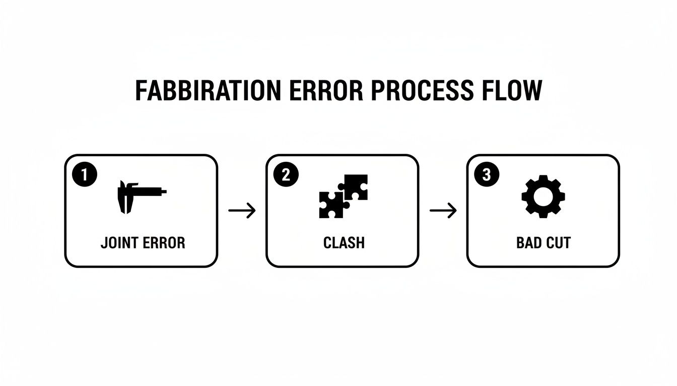
When this data is embedded in the model, the exported files carry every instruction needed. This level of discipline, explored in concepts like [designing for modular construction](https://bimheroes.com/designing for modular construction/), is the key to scalable, repeatable quality. It prevents common errors like incorrect joint tolerances, clashes, and bad cuts before they can disrupt production. The demand for such precision is growing; you can read more on the metal fabrication market's growth to see why automated accuracy is a competitive necessity.
A System for Predictable Delivery
The core lesson is this: in custom panel fabrication, precision is an engineered outcome, not an accident of effort. By implementing BIM as a precision control system, you systematically eliminate the failure points that erode margins and delay schedules.
This is about achieving production maturity. It’s about building a reliable, repeatable process that connects design intent directly to the fabricated panel, removing the friction of human interpretation. For a deeper look at the foundational documents, our guide on shop drawings for construction explains their critical role.
When your process guarantees that what you model is exactly what gets fabricated, you’re no longer just selling panels. You’re selling certainty—a far more valuable commodity.
This approach transforms your workflow from a series of risky handoffs into a seamless digital thread. It reduces RFIs, prevents costly field fixes, and delivers the operational consistency that makes complex projects profitable. The principles are central to any modern manufacturing process, as detailed in our guide on the prefabrication workflow explained.
We believe in empowering teams with the right systems. The goal is for you to feel confident that your process is built for accuracy, and to know you have a partner who understands production.
To help you implement these QA checkpoints, we’ve created a Metal Panel BIM Shop Drawing Checklist. It's a practical technical resource, not a sales tool, designed to help you build a fabrication workflow that delivers, every time.
Frequently Asked Questions
Let's address some common questions architects, consultants, and fabricators have when adopting a BIM-first approach for panel fabrication.
How does BIM handle unique or complex panel shapes?
This is a core strength of BIM. Instead of manually drawing hundreds of unique 2D panels, we use parametric families. A single intelligent family can generate countless variations based on predefined rules. Whether you need trapezoidal panels for a sloped soffit or panels notched around a structural penetration, the family adapts automatically while maintaining critical constraints like joint tolerances and material thickness. This is how you manage complexity with accuracy.
What Level of Development (LOD) is required for fabrication-ready models?
For reliable metal panel shop drawings, the model should reach LOD 350 at a minimum, with LOD 400 being the ideal target for direct-to-fabrication workflows.
- LOD 350 defines specific panel assemblies, their connections, and their coordination with adjacent systems. It is the baseline for accurate shop drawings.
- LOD 400 represents fabrication-level detail. The model includes individual panels, fasteners, and brackets modeled with precise dimensions and material data, ready for direct export to CNC machinery.
Understanding the right LOD is critical. For more detail, read our guide on Levels of Development in BIM.
Can this BIM workflow be used for materials other than metal?
Absolutely. The underlying principle—a data-rich model as the single source of truth—is material-agnostic. Whether you’re working with precast concrete, GFRC, terracotta, or composite materials, the strategy is the same. By creating intelligent parametric components within a coordinated model, you can drive shop drawing accuracy and automate fabrication data for any prefabricated system, ensuring predictability and protecting margins across your portfolio.
At BIM Heroes, we deliver clarity, systems, and reliable outcomes. We understand that production certainty is achieved through a smarter process, not just more hours.
To help your team build that process, download our complimentary Metal Panel BIM Shop Drawing Checklist. It's a practical framework to establish the QA checkpoints needed for flawless fabrication.
Get your free checklist here: https://www.bimheroes.com
