Meta description: Mechanical clashes ceiling plenum issues aren’t random. They’re the predictable result of fragmented design, 2D coordination limits, and late changes. Here’s what causes them and how teams reduce rework.
Category: MEP Engineering
Rough-in starts. The mechanical contractor lifts a main duct into place and realizes it won’t clear the beam that sits lower than everyone expected. Across the corridor, sprinkler drops land where the light fixture housings need to go. Then the ceiling height on the reflected ceiling plan turns out to depend on a plenum depth that never existed.
Many project teams have experienced this.
Nobody on site thinks the clash is acceptable. Nobody intended it. And yet the same plenum ceiling conflicts keep showing up on commercial, multifamily, and institutional projects, especially where coordination still happens through 2D overlays, separate discipline reviews, and submittals processed one package at a time.
That’s why this problem needs a different diagnosis. Mechanical clashes ceiling plenum issues are not the result of one careless designer or one inattentive reviewer. They’re the result of a workflow that asks multiple disciplines to design inside the same volume of space without a reliable shared picture of it.
Once you’ve seen enough of these jobs, the pattern gets hard to ignore. The clash that shows up in the field started much earlier, when ceiling heights were assumed instead of confirmed, when beam depths were still moving, when fixture housing depths weren’t part of the coordination conversation, or when a late reroute never made it back through a full review cycle.
The field discovery feels sudden. The cause is not.
The On-Site Clash That Was Completely Predictable
The familiar version starts with a duct.
A supply main is fabricated, delivered, and lifted. In plan, the route looked clean. It threaded past the corridor, stayed out of rated walls, and aligned with the branch takeoffs. But once the installers get under the structure, the bottom of steel leaves less room than the MEP drawings implied. The duct can’t pass where the design expected it to pass.
Then the job shifts into recovery mode.
What the field team sees first
The first sign is simple. Something won’t fit.
After that, the consequences stack quickly:
- Fabrication is suddenly wrong: Ductwork or pipe that matched the issued drawings no longer matches the actual space.
- Other trades get trapped: Sprinkler, electrical, and ceiling crews can’t finish because nobody wants to install around a conflict that may move again.
- The decision gets forced downward: Instead of resolving the plenum, teams start asking whether the ceiling can be dropped, whether a soffit can be added, or whether a reroute can be accepted.
None of those are clean fixes.
Why it wasn’t really a surprise
The hard truth is that these clashes were visible long before rough-in. They just weren’t visible in one place, at one time, to one group making a single decision.
A beam elevation sat in one set. A duct depth sat in another. Fixture requirements lived somewhere else. The reflected ceiling plan showed intent, but not the full geometry above it. Each discipline made a reasonable move inside its own scope. The project still failed to reconcile the shared space.
Field lesson: A plenum clash discovered on site usually started as an information gap, not an installation mistake.
That’s why the post-clash meeting often turns into a blame exercise that doesn’t solve anything. The mechanical contractor points to the drawings. The architect points to ceiling intent. Structural points to approved framing. Electrical points to fixture submittals. Everyone is partly right, and the clash still exists.
The issue isn’t that nobody worked. The issue is that the process never forced the full plenum to be coordinated as one system.
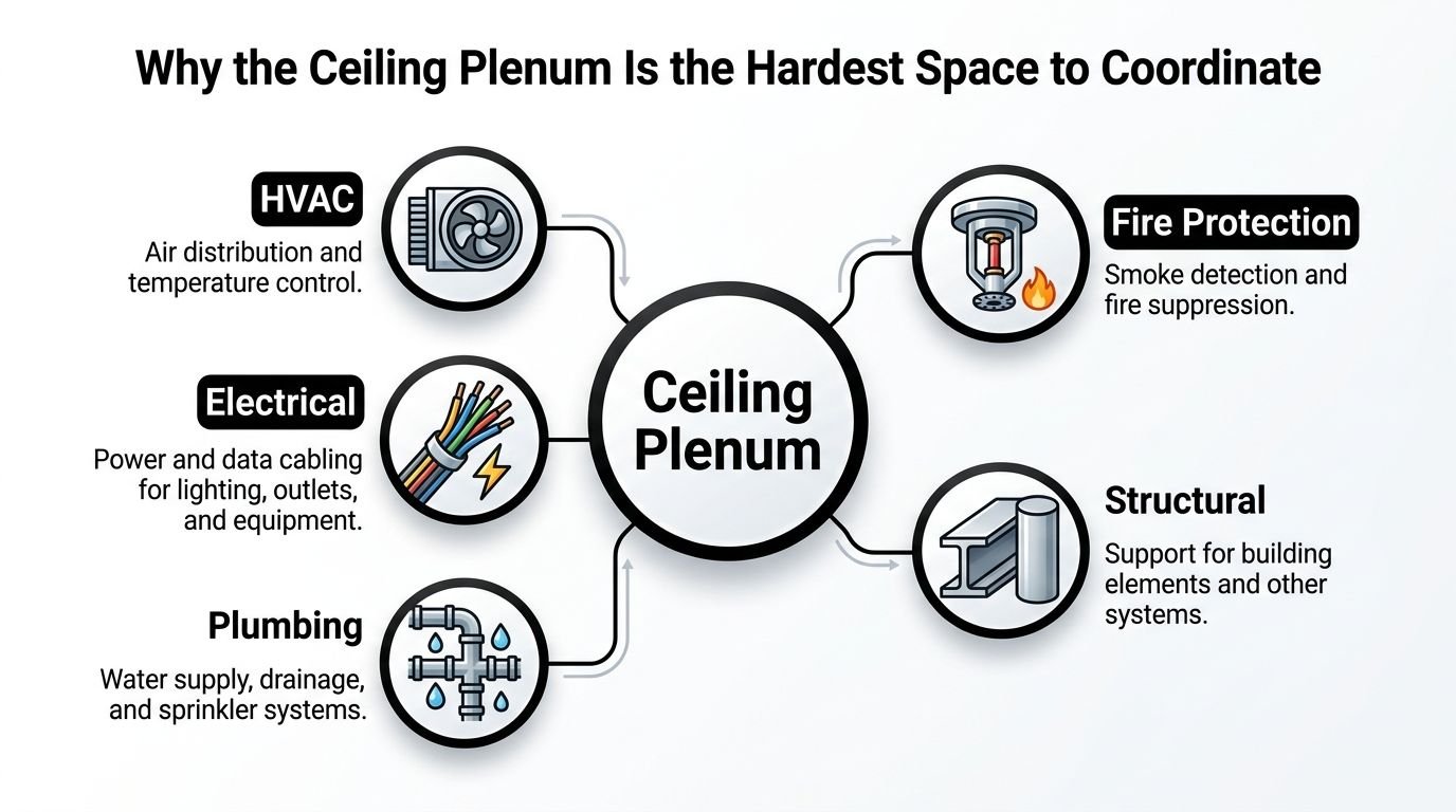
Why the Ceiling Plenum Is the Hardest Space to Coordinate
The ceiling plenum fails coordination more often than other building zones because every trade is designing into the same slice of volume, but each system follows different rules.
The plenum isn’t spare space. It is a shared service corridor squeezed between finished ceiling intent and fixed structure, and it has very little tolerance once real dimensions show up.
Every system has a valid reason for being there
That is what makes ceiling plenum coordination difficult in practice. The problem is not that one discipline is careless. The problem is that each discipline is responding correctly to its own constraints, while the project team has not yet forced those constraints into one coordinated volume.
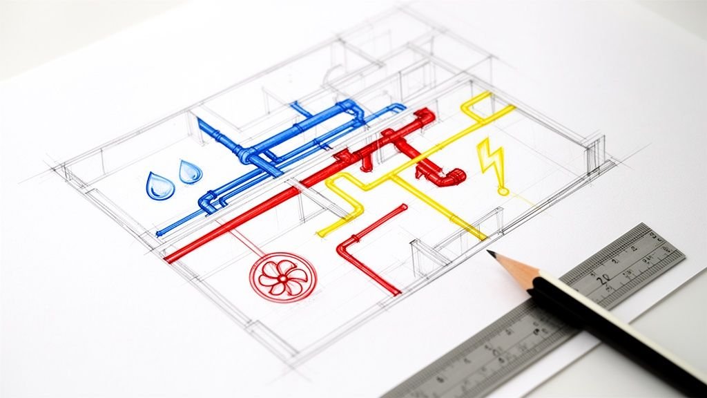
A few examples show why the space disappears quickly:
| System | What it needs from the plenum | Why it creates conflicts |
|---|---|---|
| HVAC | Large routes, turning radius, insulation, access | Duct depth consumes vertical space quickly |
| Structure | Beams, joists, bracing, framing drops | Fixed geometry forces everyone else to react |
| Fire protection | Main routing, branch lines, head placement | Coverage logic rarely aligns neatly with ceiling devices |
| Electrical | Conduit, cable tray, boxes, fixture housings | Small components multiply into crowded zones |
| Ceiling system | Suspension, fixture support, finish alignment | Finish intent depends on space that may already be taken |
The hard part is not identifying these systems. It is resolving their priorities in the right order. Structure is fixed. Large duct mains often have the fewest routing options. Gravity drainage needs slope. Sprinkler coverage has spacing rules. Lighting wants alignment with the room, not with whatever space is left over after everyone else routes around beams.
That hierarchy is rarely obvious in 2D.
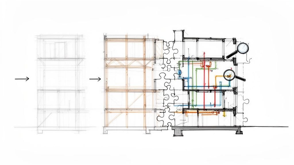
Vertical coordination breaks down first
Plan views make the plenum look manageable because each trade can trace a route across the floor plate. The conflict usually sits in section. A duct can clear a corridor on plan and still collide with a beam bottom, a cable tray stack, and a recessed fixture once actual elevations are assigned.
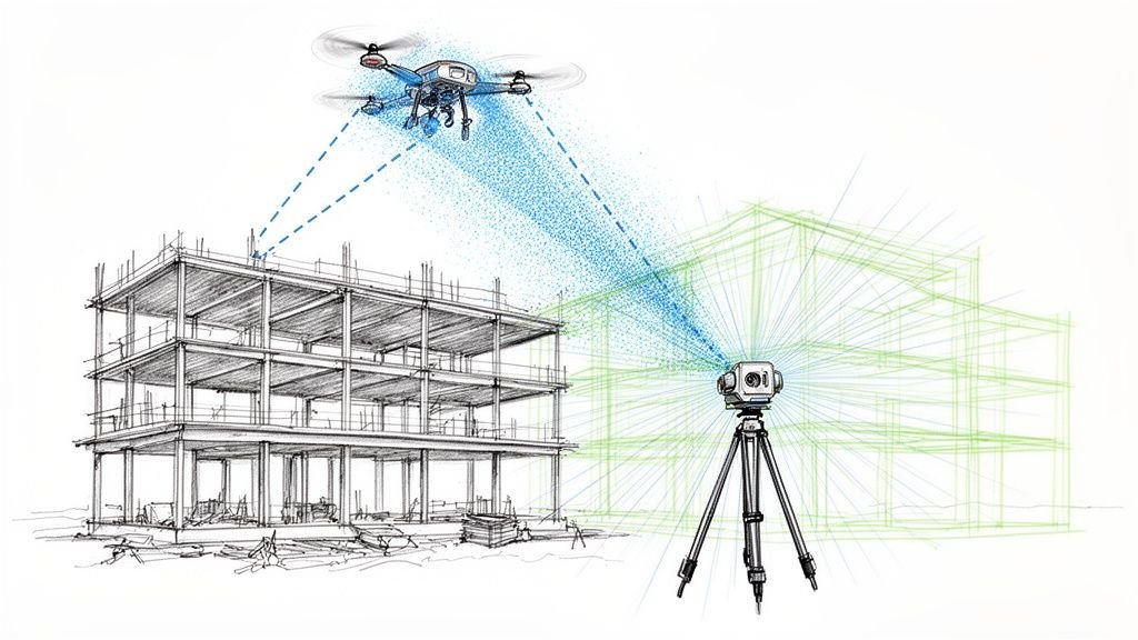
I see the same pattern on crowded jobs. Each discipline issues reasonable drawings. The combined geometry still does not fit. That is why 3D clash detection in BIM coordination workflows matters here more than in almost any other zone. The plenum is a vertical problem disguised as a horizontal one.
Code tightens the available space
The plenum also carries code constraints that limit what can go above the ceiling and what materials can be used there. For HVAC plenums, materials must be noncombustible or meet a flame spread index under 25 and a smoke developed index under 50 under IMC Section 602.2.1, as outlined in this review of materials in HVAC plenums.
That affects more than specification language. It influences routing decisions, product selection, fixture choices, and access strategy. Once the zone is crowded, code restrictions remove the informal workarounds teams sometimes rely on elsewhere.
Exposed plenums remove the last layer of forgiveness
Closed ceilings can hide some irregularity. Exposed plenums cannot.
Once the services are visible, coordination has to satisfy appearance as well as function. Routing discipline, alignment, support strategy, and finish quality all become part of the coordination problem. The same clash that might be boxed out above a lay-in ceiling can become an architectural issue in an exposed ceiling because there is nowhere to conceal a late field adjustment.
The plenum is difficult to coordinate because it concentrates fixed geometry, trade-specific rules, and finish requirements into one shallow space that traditional workflows rarely validate as a whole.
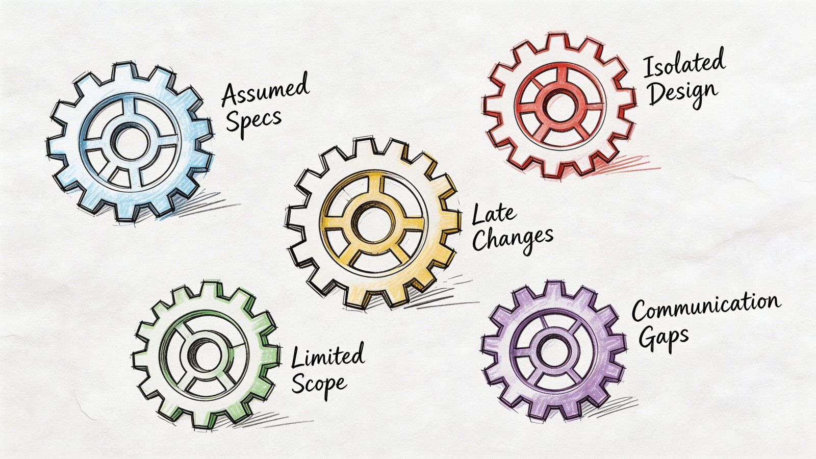
The Five Systemic Reasons Plenum Clashes Keep Happening
Recurring plenum clashes trace back to the same few workflow failures. They show up on different project types, but the mechanics are similar.
Ceiling heights get assumed before they get proven
The architect establishes ceiling intent. The mechanical engineer sizes systems to serve the program. Structural is still developing framing. Everyone moves forward because the job has to move.
That’s normal. It’s also where trouble starts.
On many projects, the ceiling height is treated as settled before the true plenum depth is confirmed against actual structure and actual system sizes. That creates a bad baseline. MEP design proceeds inside a volume that may shrink later.
Once that happens, every downstream decision inherits the error.
A corridor is a common example. The ceiling looks straightforward on plan. Then beam depths, transfer conditions, or framing transitions cut into the available zone. The main duct stays the size the load requires. The sprinkler line still needs a route. The fixture still has a housing depth. The ceiling height ends up being the only flexible element, even if nobody wanted to touch it.
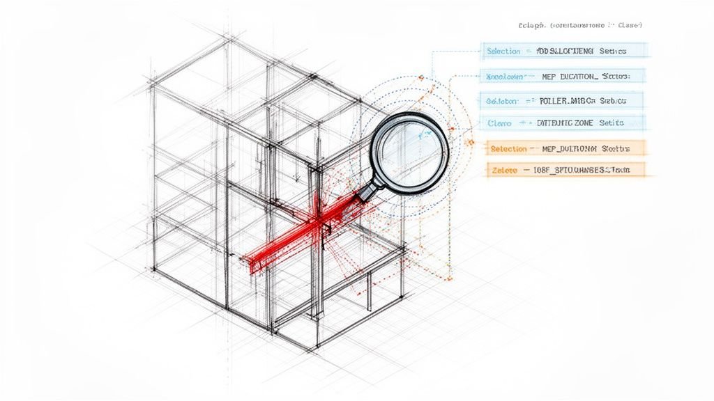
2D overlays miss the dimension where many clashes live
A lot of teams still review MEP coordination construction issues by overlaying plans. That can catch obvious horizontal conflicts. It doesn’t reliably catch vertical ones.
A duct and a beam can look perfectly compatible in plan while occupying the same space in section. A sprinkler line can miss a light fixture on the reflected ceiling plan and still conflict with the fixture body above the ceiling. A sanitary line may clear other systems in plan but lose the routing battle once slope is applied.
That’s why MEP clash detection matters. The problem isn’t that reviewers are careless. It’s that 2D methods ask people to mentally assemble three-dimensional geometry from disconnected views. That works sometimes. It doesn’t scale well on dense projects.
Teams looking to tighten that process get toward more formal clash detection in BIM because the workflow exposes spatial conflicts that overlays don’t show well.
Submittals arrive in sequence, not as one coordinated decision
Shop drawing and submittal timing creates another predictable gap.
Steel may be reviewed on one schedule. Duct shop drawings on another. Fire protection layout later. Lighting submittals later still. The reflected ceiling plan may continue changing while all of that is happening. Each package can be reviewed competently and still fail as a combined system.
This fragmentation often catches teams during the approval process.
- One reviewer checks compliance: The package appears correct inside its discipline.
- Another reviewer checks constructability: The package seems installable based on available information.
- Nobody checks the full stack together: The plenum as a shared zone never gets a single coordinated review.
That’s not a staffing issue. It’s a sequencing issue.
The plenum itself has no owner
This is one of the biggest root causes, and it’s hidden in plain sight.
Structure owns structure. Mechanical owns ductwork. Fire protection owns sprinkler routing. Electrical owns conduit and fixtures. The architect owns ceiling intent. But the plenum ceiling as a shared physical volume often has no explicit owner.
When nobody owns the space between structure and finish, each trade optimizes locally. The project then pays for the global conflict.
Coordination rule: If no one owns the plenum, the field will inherit it.
The practical effect is easy to recognize. Main routes get placed where they first seem to fit. Branches adapt around them. Ceiling devices get adjusted late. Access becomes an afterthought. Maintenance suffers because the installed condition reflects a sequence of local decisions rather than a planned layout.
Late changes don’t trigger a full re-coordination cycle
Even well-run projects drift late.
A beam gets upsized. A duct route changes to avoid another issue. A lighting package changes. A ceiling type changes. A vendor swaps one fixture for another with a deeper housing or different support condition. None of these changes looks catastrophic by itself.
The problem is what happens next. Or doesn’t happen next.
On many jobs, a late change gets reviewed only for its own discipline impact. It doesn’t get pushed back through full plenum coordination BIM or a serious equivalent process. That’s how a “small” revision becomes the source of a field conflict weeks later.
One late decision can invalidate a lot of earlier assumptions:
- Geometry changes
- Clearances disappear
- Fabrication keeps moving
- The field discovers what design never rechecked
That pattern isn’t rare. It’s built into fragmented delivery.
What a Plenum Clash Costs When Caught On Site
A plenum clash found in the field is rarely a single-fix problem. By that point, material has been bought, fabrication may be complete, hangers may already be in, and adjacent trades have planned around an assumed route. The physical interference is only the visible part.
The first costs are direct and easy to recognize. Ductwork gets remade or cut back. Pipe is rerouted. Supports move. A new penetration may need structural review before anyone drills or cores. Ceiling framing, device locations, and access panels often have to shift after layout is already set.
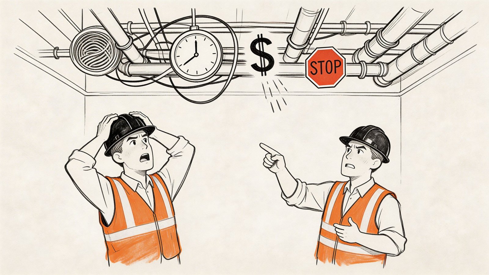
The larger hit is production loss.
Once one trade stops, the others lose their sequence. Ceiling closure gets delayed because nobody wants to bury unresolved work. Electricians and controls crews lose access. TAB work slides. Inspections have to be rescheduled around partial completion. What looked like a duct-to-light conflict turns into a floor-wide sequencing problem.
That is where field cost starts to climb. Foremen reshuffle crews. PMs issue RFIs on conditions that should have been settled before rough-in. Fabrication shops get late revision requests. Supervisors spend time negotiating space in a corridor that should already have had an agreed vertical order. Even if the rework quantity is small, the interruption is expensive.
Open plenum jobs raise the risk because there is less tolerance for field adjustment and less ability to hide compromises. As noted earlier, exposed ceiling designs demand tighter alignment and cleaner routing. A clash in that condition affects appearance, access, and owner expectations at the same time.
Teams often frame this as a software ROI question, which misses the point. The better measure is risk control. Articles on BIM coordination cost savings usually emphasize savings after conflicts are avoided. In practice, the bigger benefit is preventing one unresolved plenum condition from disrupting procurement, installation sequence, inspection timing, and finish turnover.
A field clash rarely costs what it takes to move the duct. It costs the crew hours, schedule recovery effort, and trust that get burned around the move.
There is also a less visible cost. Repeated plenum clashes teach the site team that the drawings are provisional. Once that happens, every install slows down because crews start checking around the documents, asking for confirmations, and protecting themselves against the next surprise.
That is not a people problem. It is a process failure showing up at the worst possible time.
Why Catching Vertical Conflicts in 2D Is So Difficult
2D workflows aren’t useless. They’re just structurally limited for this specific problem.
A plan overlay can tell you whether two elements occupy the same horizontal area. It cannot reliably tell you whether they clear each other vertically once all real-world conditions are applied. That missing dimension is where many ductwork ceiling conflicts occur.
The missing information isn’t trivial
For a plenum conflict to be caught in 2D, the reviewer has to mentally combine multiple facts that often live on different sheets or in different submittals.
A typical reviewer may need to know all of this at once:
| Item | Why it matters in the plenum |
|---|---|
| Duct depth plus insulation | Determines real installed depth, not nominal shape only |
| Bottom-of-steel elevation | Sets the true upper limit for routing |
| Lighting housing depth | Consumes space that plan symbols don’t show |
| Pipe slope | Changes elevation continuously along the run |
| Ceiling suspension and support | Occupies space often treated as negligible until it isn’t |
Any one of those can break the route. Combined, they create a coordination problem that 2D documents don’t naturally reveal.
Small components become major vertical conflicts
Lighting is a good example because it looks simple on paper.
Chicago Plenum-rated IC boxes for recessed lighting have stringent installation requirements, including no holes, tightly overlapped or gasketed seams and joints, flush or press-back knockouts, and gasketed junction box covers opening into the ceiling, as explained in this overview of Chicago plenum fixture requirements. Those are not abstract details. They affect fixture enclosure geometry, placement, and the clearances around it.
What looks like a clean symbol on an RCP can become a real three-dimensional object competing with duct, sprinkler, conduit, and ceiling support in a tight zone.
Reviewers are being asked to do mental modeling
That’s the practical limitation of 2D plenum review. It depends on individual reviewers mentally modeling the space with imperfect inputs.
Some people are good at that. Good teams still miss clashes because the workflow itself is fragile.
The more congested the plenum gets, the less realistic it is to expect reliable 3D decisions from disconnected 2D views.
This isn’t a criticism of drafting discipline. It’s a recognition that the coordination burden rises faster than the drawing method can comfortably support.
How BIM Coordination Specifically Solves Plenum Conflicts
A coordinated model doesn’t solve the plenum because it’s fashionable. It solves it because it puts the actual competing geometry in one place before fabrication locks the job in.
That matters most in the spots where teams get surprised.
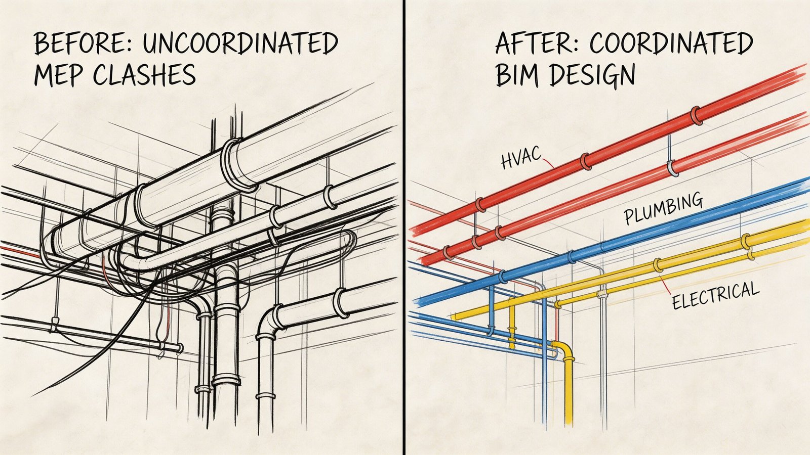
What becomes visible early
In a coordinated model, the team can check real routing against real constraints.
That includes:
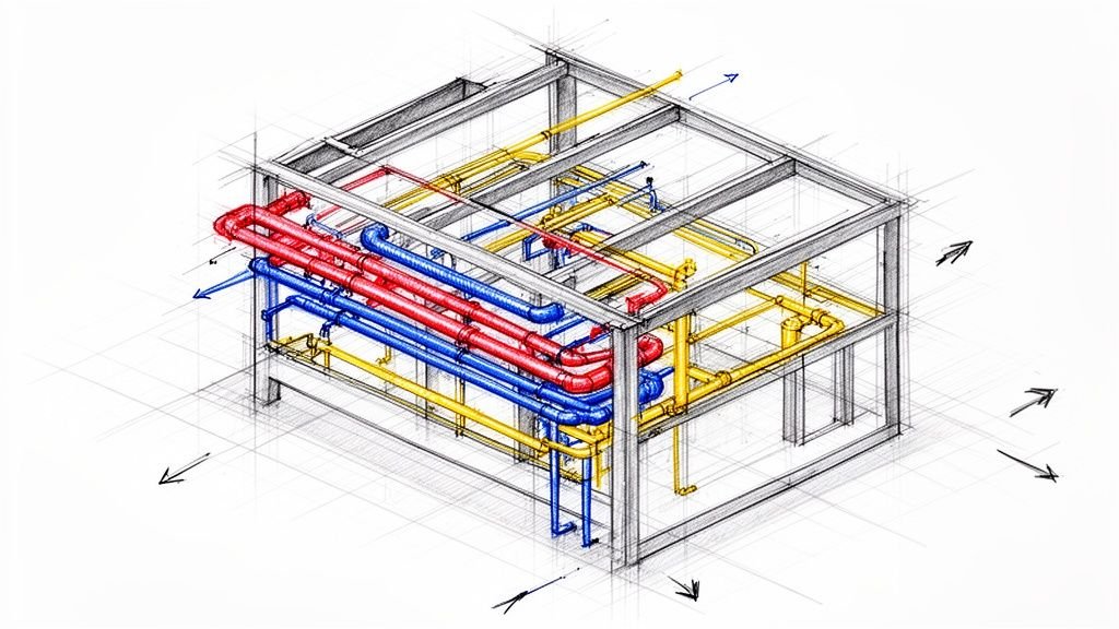
- Duct against structure: Main runs can be tested against beam depth and framing conditions before shop drawings drive fabrication.
- Sprinklers against ceiling devices: Head locations can be reviewed with lights, diffusers, and access panels as actual objects, not symbolic overlaps.
- Ceiling height against system depth: The proposed finished ceiling can be checked against the true build-up above it.
That changes the timing of the decision. Instead of discovering a conflict after material is on site, the team resolves it while alternatives are still cheap.
The model supports decisions, not just clash reports
Good plenum coordination BIM isn’t just about generating a list of collisions.
It helps teams answer practical questions early:
- Should the corridor main shift?
- Does the branch routing need to swap elevation with another trade?
- Is the ceiling height still realistic?
- Does a fixture type need to change?
- Should a congested zone be detailed with a dedicated section and agreed routing rules?
That’s where coordination becomes production control. The model helps teams decide, document, and hold a coordinated condition.
For firms building that capability in-house, practical workflows around MEP in Revit matter more than flashy visuals. The value is in disciplined geometry, usable families, decision checkpoints, and a review process that catches conflicts before they multiply into RFIs and field workarounds.
Better inputs create better fabrication outcomes
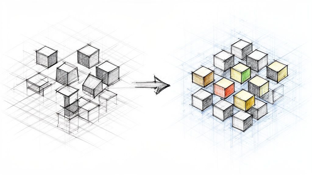
The biggest gain is predictability.
When the routing has already been checked against structure, ceiling components, and adjacent systems, fabrication packages are based on something closer to the truth of the building. That improves install sequencing, reduces rework pressure, and gives the field a layout they can trust.
Production view: BIM coordination earns its value when it turns uncertain space into agreed space.
That’s the core shift. Not from 2D to 3D as a software upgrade, but from assumption to confirmation before construction starts making assumptions expensive.
Better Plenum Coordination Without a Full BIM Mandate
Not every project has a formal clash detection requirement. Not every owner will pay for full-model coordination. Teams have ways to improve outcomes if they’re willing to tighten process discipline.
The key is to act like the plenum is a managed zone even if the project isn’t running a full digital coordination workflow.
Set plenum rules earlier than is typical
The easiest mistake is waiting too long to define who gets what space.
During design development, teams can agree on rough routing priorities in congested areas. Not every inch needs to be fixed, but the hierarchy should be clear. Main ducts don’t belong in the same decision bucket as branch conduit. Sloped plumbing needs different treatment than level piping. Fixture depths should be known before ceiling intent gets treated as final.
That kind of early zoning reduces ambiguity.
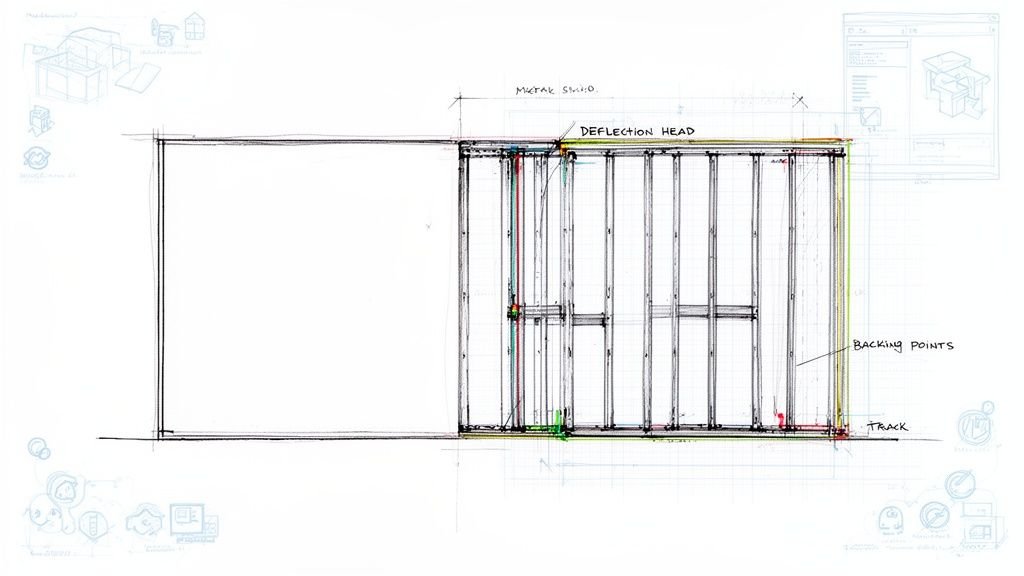
Use sections where plans stop helping
In dense corridors, lobbies, and equipment-adjacent ceilings, permit sets should include real section cuts through the trouble spots.
Not decorative sections. Coordination sections.
A good section forces the team to look at:
- Bottom-of-structure conditions
- Largest MEP elements
- Ceiling system depth
- Fixture and device requirements
- Remaining access for maintenance
That’s enough to expose a bad assumption before it becomes a field problem.
Treat the reflected ceiling plan like a coordination document
Many teams use the RCP as a finish layout only.
In reality, the RCP is one of the best early warning documents for plenum congestion. Lights, diffusers, sprinkler heads, speakers, access panels, and detectors all appear there. If the RCP is reviewed only for alignment and aesthetics, the project misses a major coordination checkpoint.
The better habit is to review it with MEP and ceiling support conditions in mind.
Review every dense RCP area as if it were a section problem, because that’s what it becomes in the field.
Confirm structural depth before MEP design hardens
A lot of avoidable ceiling plenum coordination failures start when MEP sizing proceeds against structure that is still conceptually right but geometrically unstable.
That doesn’t mean MEP must stop. It means there should be a formal checkpoint where beam depths, drops, and bottom chord elevations are confirmed before system sizing and major routes become difficult to change.
That single discipline can prevent a lot of late redesign.
Choose components that simplify the plenum
Product selection matters more than teams sometimes admit.
For tight spaces, systems like Armstrong’s ShortSpan can support spans up to 8'-6" without mid-span hanger wires, which can reduce interference points and improve access in crowded plenums, as described on Armstrong’s low-plenum corridor systems page. Choices like that don’t eliminate coordination, but they can make the plenum less congested and easier to maintain.
That’s a design-phase move with downstream payoff.
Owning the Plenum Before It Becomes Everyone's Problem
Plenum clashes keep happening because the process keeps allowing them to happen.
The common pattern is straightforward. Each discipline develops valid work inside its own scope. The project never fully reconciles the shared volume above the ceiling. Then construction becomes the first moment when the entire condition is forced into physical reality at once.
That’s why these conflicts feel repetitive. They are.
The fix starts with ownership. Someone has to treat the plenum as a single coordinated space, not as leftover room between structure and finish. On some projects that’s the architect. On others it’s the GC, the MEP lead, or a BIM coordinator. The title matters less than the responsibility.
What matters is that somebody asks the questions early enough to change the answer.
Is the ceiling height buildable?
Do the biggest systems have a viable route?
Are fixture and sprinkler locations compatible with what sits above them?
Did the late change go back through coordination, or just through approval?
When teams build those checkpoints into production, the job gets calmer. Fewer RFIs. Fewer field improvisations. Better permit readiness. Better fabrication confidence. Better margin protection.
A plenum ceiling doesn’t become coordinated by accident. It becomes coordinated when the team decides the shared space has to be managed as deliberately as every discipline inside it.
If your team is trying to make plenum coordination more predictable, BIM Heroes shares practical frameworks around BIM production, QA workflows, and coordination systems that help AEC teams reduce rework before it reaches the field. You can explore those resources at BIM Heroes.