Meta description: Scan to BIM accuracy isn’t one number. Learn how scanner precision, registration, LOD, modeling decisions, and QA checks affect trust in scan-to-BIM services.
A renovation team gets an as-built model back, loads it into Revit, and starts moving fast. The plan feels solid. Existing walls are there, core elements are in place, and everyone assumes the geometry is reliable enough to begin layout, detailing, and coordination.
Then the site visit happens.
A few field checks show that key wall locations don’t quite match what the model suggests. Nothing dramatic. But the mismatch is big enough to affect millwork clearances, ceiling coordination, or a tight restroom layout. At that point, the argument usually starts in the wrong place. People ask whether the scan was wrong.
Often, the scan wasn’t wrong. The underlying problem is that Scan to BIM accuracy was treated like a fixed promise instead of a scoped requirement. Predictability suffers in such situations. The issue isn’t whether scan-to-bim services work. It’s whether the team defined what “accurate enough” meant for this building, this use case, and this deliverable.
The Accuracy Mismatch That Derails Projects
Most accuracy disputes start with an assumption gap.
The architect assumes the model reflects real conditions closely enough for detailing. The scanning team assumes the model will be used for general renovation planning. The modeling team builds to the stated scope, not the unstated expectation. Everyone feels reasonable, and the model still becomes a problem.
That matters because this is no longer a niche workflow. North America holds over 35% of the global Scan-to-BIM market share as of 2024, and mid-sized projects typically cost $5,000 to $50,000 according to ViBIM’s summary of Scan-to-BIM market trends. When that much time and money sits behind a deliverable, a blurry definition of accuracy can erode the value quickly.
What the project team usually misses
The conflict is rarely about whether a provider delivered files.
It’s usually one of these:
- Assumed design use: The team starts using the model for detailed fit-out decisions when the scope supported broader planning.
- Critical zones not separated: High-risk areas like shafts, plant rooms, storefronts, and tight interiors needed tighter control than the rest of the building.
- Tolerance never stated: The contract mentions LOD, file format, and disciplines, but says little about acceptable dimensional deviation.
- Omissions get mistaken for errors: If embedded conditions, irregular framing, or above-ceiling MEP weren’t included, the model can look “wrong” even when it’s just incomplete.
A model can be within scope and still be the wrong model for the decision you’re trying to make.
Why this turns into margin erosion
Small dimensional surprises create big downstream waste.
A misread partition location can force redraws. A simplified ceiling zone can trigger avoidable RFIs. A generalized slab edge can compromise prefabrication assumptions. None of those failures show up on day one. They appear later, when the model has already become the team’s working base.
That’s why project architects and BIM managers need to treat laser scanning accuracy BIM claims carefully. “Accurate” by itself doesn’t mean much. Accurate for permitting, accurate for concept design, accurate for fabrication, and accurate for FM handover are not the same thing.
Scanner Accuracy vs Model Accuracy
A project team approves a scan because the hardware spec looks tight. Weeks later, the architect starts dimensioning millwork off the model and finds wall faces that do not line up with field conditions. The scanner did its job. The model still failed the decision it was being used for.
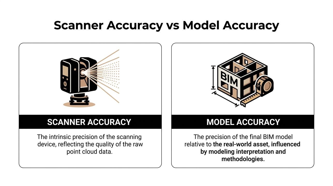
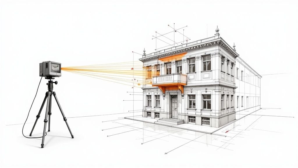
Scanner accuracy is capture accuracy
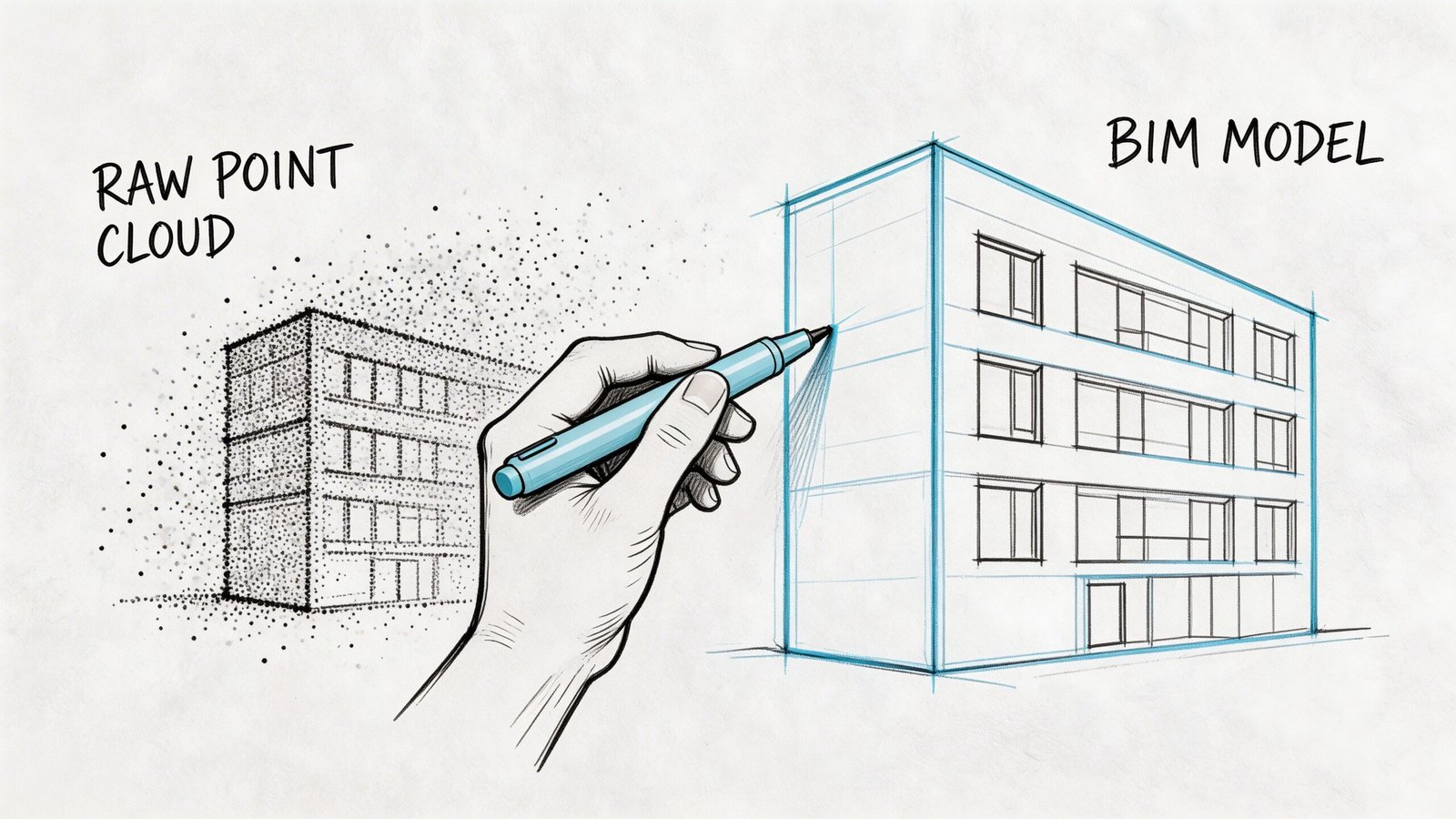
Scanner accuracy describes how well the equipment records existing conditions and how well the scans are registered into a usable point cloud. That includes instrument performance, control, scan setup, overlap, and registration discipline.
A high-quality point cloud can be very precise and still leave room for error in the BIM deliverable. The cloud is measured evidence. The model is a constructed interpretation of that evidence.
Point cloud quality still matters. If the dataset is noisy, incomplete, or poorly registered, the modeler starts from weak information. Teams that need dependable geometry should review the provider’s process for cleaning and preparing point cloud data for accurate models before modeling starts, not after discrepancies show up in Revit.
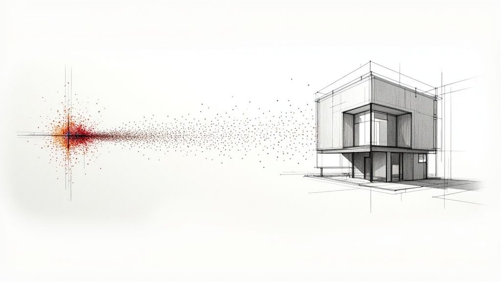
Model accuracy is representation accuracy
Model accuracy depends on what gets modeled, how it gets modeled, and what tolerance the team accepts for each element category.
That gap shows up fast in existing buildings. A wall may bow across its length, taper at one end, or drift out of plumb floor to floor. The modeler has to choose whether to fit a straight wall to the dominant face, split it into segments, or note the deviation outside the model. Each option can be correct for one use and wrong for another.
This is the production risk in scan-to-BIM. Hardware captures reality. Modeling turns irregular conditions into usable objects, and every simplification changes what the file can support.
Where teams get caught
The problem usually is not bad intent. It is a bad assumption about what “accurate” meant in the proposal, in the execution plan, or in the reviewer’s head.
| Topic | Scanner accuracy | Model accuracy |
|---|---|---|
| Primary concern | Reliability of the captured scan data | Reliability of modeled geometry for a stated use |
| Controlled by | Equipment, control, scan coverage, registration | Scope, element breakdown, modeling rules, QA review |
| What gets missed | Capture limits in hidden or reflective areas | Averaging, straightening, omission, or generalized geometry |
| Common bad assumption | “The point cloud is precise, so the model will be too” | “The model should reproduce every irregular condition” |
A point cloud can support several modeling approaches. The deliverable only becomes trustworthy when the approach matches the decisions the design team plans to make.
The question to ask before you approve the deliverable
Ask for the model tolerance by use case and by element type.
That means plain language, not marketing language. For walls, structure, slab edges, MEP mains, and high-risk rooms, ask how the modeled geometry is derived from the cloud, what deviation is acceptable, and how exceptions are flagged. If a provider answers with scanner specifications alone, they have not answered the core accuracy question.
Architects and facility teams do not work from hardware specs. They work from modeled objects, dimensions, clearances, and locations. The useful question is simple. How closely does this BIM deliverable represent existing conditions for the decisions we need to make?
What Affects Point Cloud Accuracy On Site
A renovation team approves a scan because the cloud looks sharp in the viewer. Two weeks later, the model starts missing clearances above the ceiling, a core wall is slightly off grid, and nobody can tell whether the problem came from capture, registration, or modeling. That is a common production failure. The field capture looked finished before the risk was understood.
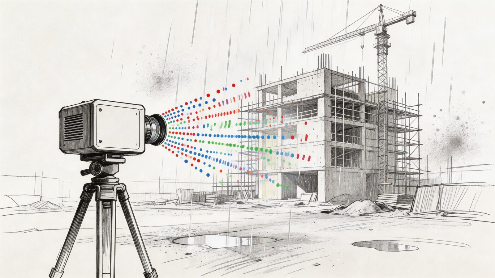
Hardware performance changes with context
Scanner specs are measured under controlled conditions. Existing buildings are rarely controlled.
Distance affects point density. So do incidence angle, line of sight, surface finish, and whether the scanner is reading glass, black paint, foil-faced insulation, or polished metal. Add an active site with workers, lifts, temporary protection, and partial access, and the cloud can lose reliability in exactly the places the design team cares about most.
The practical issue is coverage, not just stated hardware precision. If the scanner cannot see the surface well, the cloud may still look usable at screen level while carrying weak geometry, shadows, or noisy returns.
Registration quality sets the floor for everything that follows
One setup never captures a building well enough for production work. The scan team stitches many setups into a single registered dataset, and that step deserves direct scrutiny.
Bad registration creates a coordinated-looking cloud that is slightly wrong across larger extents. On a tenant fit-out, that may show up as wall faces that do not hold dimension consistently. On a hospital wing or plant room with many setups, small alignment errors can stack up into drift that affects layouts, sleeve locations, and tie-ins. If the provider cannot explain how registration was checked, the modeling team is starting from an unstable base.
Site conditions create noise, gaps, and false confidence
Some conditions reduce data quality. Others hide the condition entirely.
Common problem areas include:
- Glass and reflective finishes: returns can scatter or mirror adjacent geometry
- Dark or absorbent materials: surfaces may read thin, patchy, or incomplete
- Occupied or active spaces: people, carts, doors, and equipment introduce transient noise
- Congested above-ceiling zones: ducts, cable tray, hangers, and insulation block visibility
- Restricted access areas: locked rooms, high ledges, shafts, and live spaces often remain partially captured
Cleaning helps, but it does not recover missing visibility. Teams that need a refresher on preprocessing should review how to clean point cloud data for accurate models before setting model assumptions.
If a beam seat, pipe offset, or wall bow never made it into the cloud, the modeler has only two options. Omit it or guess.
Survey control and internal fit are different checks
A cloud can register well internally and still be wrong relative to project coordinates. That distinction matters on phased work, campus projects, facade packages, and any job that has to align with prior survey, civil data, or consultant models.
I have seen datasets that looked clean in isolation but arrived rotated, shifted, or vertically biased against the control network. The fix is rarely cheap once modeling has started. Coordinate verification belongs at the front of the job, not at model exchange.
What to confirm before modeling starts
A short field-to-office review catches many of the problems that later get mislabeled as "BIM accuracy" issues:
- Was the scan tied to survey control or project coordinates? Ask what control was used and how it was checked.
- How was registration validated? Ask for the report, residuals, target method, or other verification record.
- Where are the blind spots and access limits? Every dataset has them. They should be mapped, not buried.
- Which materials or zones produced weak returns? Reflective, dark, and occupied areas should be flagged for the modelers.
- Was the cloud cleaned and segmented before handoff? Production teams should not discover noise, duplicates, or misclassified areas halfway through modeling.
- What areas need re-scan or field verification? It is better to identify exceptions early than to model uncertainty as fact.
Those checks set expectations where they belong. Site capture can support a reliable BIM deliverable, but only if the team separates clean-looking scan data from verified, usable existing-conditions information.
How Modeling Decisions Affect Final BIM Accuracy
Even strong scan data can produce a weak model if the production rules are loose. Most project architects typically underestimate this problem. The model isn’t a neutral export from the point cloud. It’s a translation.
LOD changes what “accurate” means
A low-detail model can still be useful. It just can’t support every decision.
If the scope is set around LOD 200, geometry is intentionally generalized. That may be enough for planning, broad clash review, or area studies. It is not the same as a model built to support tight renovation detailing, dense coordination, or fabrication-sensitive conditions.
The mistake is asking for one global LOD and assuming that covers every zone equally well. It rarely does. If you need a quick reference on this, BIM Level of Detail is one of the first scope items worth aligning internally before procurement.
Parametric modeling forces judgment calls
Real buildings are messy. Revit objects prefer consistency.
A few common examples show where point cloud to BIM accuracy gets negotiated:
- Out-of-plumb walls: Does the model follow the lean, the centerline, or the best-fit vertical plane?
- Irregular slabs: Does the model represent the highest point, lowest point, or an averaged surface?
- Curved or deformed elements: Does the team model exact shape, segmented approximation, or a simplified family?
- Congested MEP: Are systems modeled as true geometry, centerlines, or clearance volumes?
Those are not software quirks. They are production decisions. If they aren’t stated in the scope, the team will make them anyway.
Tolerance belongs in the modeling brief
LOD alone isn’t enough. A model can be “LOD 300” and still be too loose for your intended use if no tolerance language backs it up.
Validation checks often compare the final model against the point cloud, with deviations under 5 mm used as a typical benchmark for high-quality scans. Hitting that level usually requires both automated segmentation and manual refinement, with 99% fidelity cited for prefabrication-oriented tasks in Techture’s introduction to scan-to-BIM and laser scanning.
That benchmark is useful, but the larger lesson is more important. High fidelity takes deliberate effort. It doesn’t happen because someone imported an RCP into Revit.
Field lesson: If the scope doesn’t state tolerance, the provider will default to what is commercially reasonable for their workflow, not what is mission-critical for your design package.
Completeness and accuracy are different problems
Many “accuracy” complaints are completeness complaints.
If the model omits existing MEP above the ceiling, structural embeds at critical openings, or nonstandard framing at a stair connection, the team experiences that omission as unreliable geometry. But the fix isn’t arguing about scanner performance. The fix is defining what had to be modeled in the first place.
A useful review framework looks like this:
| Question | Accuracy issue | Coverage issue |
|---|---|---|
| Does the modeled wall sit where the point cloud indicates? | Yes | No |
| Was the wall modeled at all in the critical area? | No | Yes |
| Is the floor represented with enough fidelity for leveling decisions? | Yes | Sometimes |
| Were ceiling services included for coordination? | Not necessarily | Usually the key problem |
Production maturity shows up here. Teams that separate fidelity, abstraction, and omission make better decisions and avoid blaming the wrong stage of the workflow.
Understanding Industry Tolerance Benchmarks
There isn’t one universal tolerance that defines trustworthy scan-to-bim services. The useful benchmark depends on what you need the model to do next.
That’s why a discussion about Scan to BIM tolerances should start with use case, not software.
Match tolerance to decision risk
If the model is mainly for planning, code study support, broad renovation layout, or facility reference, a more generalized output may be perfectly acceptable. In those cases, over-modeling creates cost without improving decisions.
If the model will drive tight interiors, MEP reroutes, storefront replacement, millwork interfaces, or prefabricated components, tolerance expectations need to be tighter and the review process more deliberate.
Teams often overspend or underbuy in this situation.
- Too loose: The model can’t support the detail decisions the project team assumes it can.
- Too tight: The provider spends time modeling conditions that don’t affect the actual workflow.
- Poorly distributed: Low-risk areas get the same treatment as high-risk zones, which wastes budget.
Complex interiors are where confidence drops
Interior retrofits are a frequent trouble spot because conditions are cluttered, layered, and irregular.
Real-world projects show that a 10 to 15% accuracy loss is possible in complex interiors when converting point clouds into models. The same body of guidance also notes that smart LOD trade-offs matter, and that LOD 200 can be sufficient for high-level clash detection when a full LOD 500 model would be unnecessarily expensive according to MaRS BIM’s discussion of scan-to-BIM accuracy and construction workflows.
That doesn’t mean complex interiors are unreliable by default. It means they require more selective modeling strategy.
Don’t ask for the highest fidelity everywhere. Ask for high fidelity where a wrong assumption becomes a redesign.
A practical way to think about tolerance
Instead of asking for “maximum accuracy,” ask which category your decisions fall into:
Reference use
Good for planning, documentation support, and general context.Design coordination use
Good for spatial fit, system routing, and early clash avoidance.Fabrication-sensitive use
Needed when components must fit existing geometry with very little field adjustment.
The smartest scopes define different expectations for each area of the building. That keeps budget aligned with project risk.
How to Specify Scope to Get the Accuracy You Need
Most bad outcomes in scan-to-bim services are purchased accidentally. The scope sounds complete, but it leaves too much open to interpretation.
Define the model by use, not by software output
Start with the decision the model needs to support.
Is it for permit background and design setup? Renovation coordination? Existing-condition verification before prefabrication? Record documentation for operations? Those are different deliverables, even if they all arrive as RVT files.
If you skip this step, the provider has to guess what matters most.
Write scope by zone and system
Blanket language creates uneven value.
A better approach is to specify fidelity where risk sits. That usually means separating core areas, public interiors, MEP-heavy spaces, façade interfaces, and low-risk support zones. Architectural, structural, and MEP elements may also need different expectations.
Scan-to-BIM costs can range from $0.25 to $1.50 per square foot for scanning and another $2.00 to $5.00+ for modeling, depending on complexity and LOD. Those cost bands make detailed scope and tolerance language essential if you want predictable ROI and fewer budget overruns according to GP-Radar’s overview of scan-to-BIM cost structure and ROI questions.
That pricing range is exactly why broad, vague scopes become expensive.
Include these items in the brief
Use a short control list before issuing procurement or approving production:
- Intended use: State whether the model supports planning, design coordination, fabrication-sensitive review, or FM.
- Critical elements: Identify the walls, slabs, ceilings, structure, façade edges, plant rooms, risers, or equipment zones that drive decisions.
- Tolerance expectations: State them explicitly for the elements that matter most.
- LOD by area: Don’t assign one blanket LOD if some spaces need more fidelity than others.
- Modeled versus referenced: Clarify whether MEP should be modeled as geometry, centerlines, or only retained in the point cloud.
- Coordinate requirements: Say whether the model must align to survey control or internal project coordinates.
- QA deliverables: Request deviation checks, issue logs, or screenshots for high-risk zones.
Ask for production logic, not just delivery dates
A good provider should be able to explain how they’ll build the model, not just when they’ll send it.
That means talking through software stack, review sequence, family strategy, and point cloud handling. If your team is comparing workflows, this page on point cloud software is useful background because software choices affect registration review, visualization, and model handoff quality.
What doesn’t work
These scope phrases cause trouble fast:
- “Model existing conditions accurately.”
- “Provide as-built BIM at LOD 300.”
- “Include all visible elements.”
- “Suitable for renovation.”
None of those statements tells the production team enough.
The safer version is more specific. Name the decision, the area, the systems, the tolerance expectation, and the omissions that are acceptable. That’s how you get margin protection instead of revision cycles.
A Realistic QA Checklist for Your BIM Deliverable
When the model arrives, don’t jump straight into production. Run a first-pass review before your architects, engineers, or facility team begin relying on it.
This doesn’t need to become a forensic audit. It needs to catch trust-breaking issues early.
Start with a few high-risk checks
Pick the areas where bad geometry would hurt the most.
That usually includes shafts, stairs, restroom cores, façade edges, plant rooms, low-clearance ceiling zones, and any area where new work has very little tolerance for surprise.
Use a simple sequence:
Spot-check critical dimensions
Compare a few key distances against field measurements or trusted control dimensions.Overlay model against point cloud
Review visually in Revit, Navisworks, ReCap, or the agreed viewer. Look for obvious drift, averaged geometry, or elements not following the cloud.Check known control locations
If survey control or benchmarks were part of the job, verify those first.
Confirm that the deliverable matches the brief
A model can be geometrically decent and still fail the project if it misses scope intent.
Review these items directly against the signed scope:
- LOD by element or zone: Was the expected level of development delivered where needed?
- Modeled disciplines: Are architecture, structure, and MEP represented at the agreed level?
- Omissions: Is there a clear list of what wasn’t modeled?
- Coordinate setup: Does the file sit where the rest of the project expects it to sit?
Look for abstraction that changes decisions
Some simplification is normal. Harmful simplification is not.
Watch for:
- walls modeled straight where the cloud shows meaningful deviation
- slabs flattened where drainage, level changes, or transitions matter
- MEP represented too loosely for clearance decisions
- storefronts, soffits, or framing zones simplified beyond useful design intent
If a simplification changes a design decision, it isn’t harmless abstraction anymore.
Keep a short issue log
Don’t bury review comments in screenshots and email chains. Use a compact log with four columns:
| Location | Issue | Risk to project | Action |
|---|---|---|---|
| Level and grid reference | What appears off or missing | Design, coordination, permit, or install impact | Clarify, revise, field-check |
That keeps QA tied to project consequences, not personal preference.
What a first-pass review should answer
By the end of this review, you should know four things:
- Can the team trust the model for the decisions planned this week?
- Where does field verification still matter?
- Which omissions need supplementary capture or modeling?
- Are there any areas that should be frozen until clarified?
That level of review prevents the common failure mode. A model enters production, gets trusted too quickly, and then leaks error into CDs, coordination, and site work.
Accuracy Is an Outcome Not a Feature
The safest way to think about Scan to BIM accuracy is this. It isn’t a product feature you buy once. It’s an outcome created by field conditions, registration quality, modeling choices, scope language, and QA discipline.
That’s why scan-to-bim services can feel excellent on one project and disappointing on another, even when the same tools are involved.
Teams that get reliable results usually do a few things well. They define use cases before procurement. They ask for tolerances where risk is real. They separate high-value zones from low-value zones. They review the model against the point cloud before turning it into the basis for design. And they don’t confuse a clean scan with a fully decision-ready BIM.
The firms that struggle tend to do the opposite. They assume “accurate” means universally accurate. They use one LOD label to cover the whole building. They skip omission review. They discover limitations only after drawings are underway.
That difference isn’t academic. It affects RFIs, redesign time, permitting confidence, and coordination stability. It also affects fee protection. When teams specify clearly and review early, they avoid spending design hours correcting a mismatch that was built into the brief from day one.
If you’re evaluating a recent deliverable or preparing a new scope, treat Scan to BIM tolerances as a production requirement. Not a marketing phrase. That mindset leads to better models and fewer surprises.
If you want a practical second set of eyes on your next scan-to-BIM scope, or a clearer QA framework your team can use before design starts, BIM Heroes has resources that can help you turn vague accuracy expectations into a repeatable review process.