Meta description: Design for manufacture and assembly DfMA architecture explained for architects and design-build teams. Learn what changes in SD, DD, BIM, and MEP when prefab and modular delivery are on the table.
An architect gets a modular project, designs it the usual way, and expects the prefab team to “make it work.” Then the manufacturer reviews the model and starts marking up problems that should never have survived schematic design.
The corridor geometry doesn’t line up cleanly with the module strategy. The bathroom layout can’t be standardized into a repeatable pod without forcing awkward utility connections. The structural grid creates partial conditions at the ends of the floor plate, so the plant now has to build custom edge units instead of repeating a clean run. None of that is a shop problem. It’s a design problem.
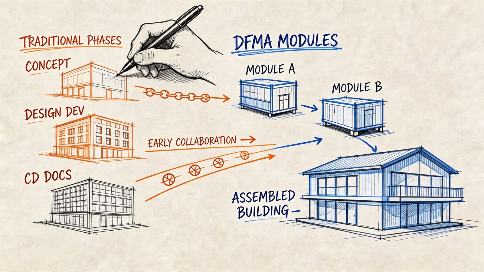
That’s the core principle of design for manufacture and assembly. In architecture, DfMA isn’t just about using prefab components or buying modular units. It’s a way of designing so the building can be produced, transported, and assembled with consistency.
Architects usually work in a sequence that rewards deferring commitment. Explore massing first. Refine plans later. Let structure settle. Push MEP coordination downstream. That sequence works on many conventional projects. It fails fast on DfMA construction AEC projects because early design decisions are also production decisions. If you make them without factory logic in the room, you create avoidable cost, rework, RFIs, and schedule risk.
The DfMA Disconnect Why Traditional Design Fails Prefab Projects
Most first-time prefab teams don’t fail because they lack software. They fail because they’re still designing for site improvisation.
Traditional architectural process assumes the field can absorb ambiguity. A framer can shim. A trade can reroute. A superintendent can sequence around an unresolved interface. That tolerance for late adjustment is built into conventional delivery. It’s also expensive, but the industry is used to it.
DfMA removes that cushion. Factory work depends on repeatability. Assemblies move through stations in a defined order. Connection points have to land where the model says they land. The more variation you introduce, the more you interrupt production.
Practical rule: If a decision affects how something will be built repeatedly, it belongs earlier in design than most teams think.
That changes the architect’s role. You’re no longer only defining spaces, materials, and intent. You’re defining production logic. Unit types, corridor widths, riser locations, façade repetition, pod boundaries, and grid discipline all become manufacturing inputs.
A lot of teams still treat this as a contractor-side issue. It isn’t. By the time a modular fabricator or prefab MEP partner sees a half-developed design, the greatest flexibility is lost. The geometry is already set. The variation is already baked in. The most expensive conversations now start with “Can we still make this work?”
On a DfMA project, the better question is simpler. What must be fixed early so the building can be made cleanly, repeatedly, and with minimal field correction?
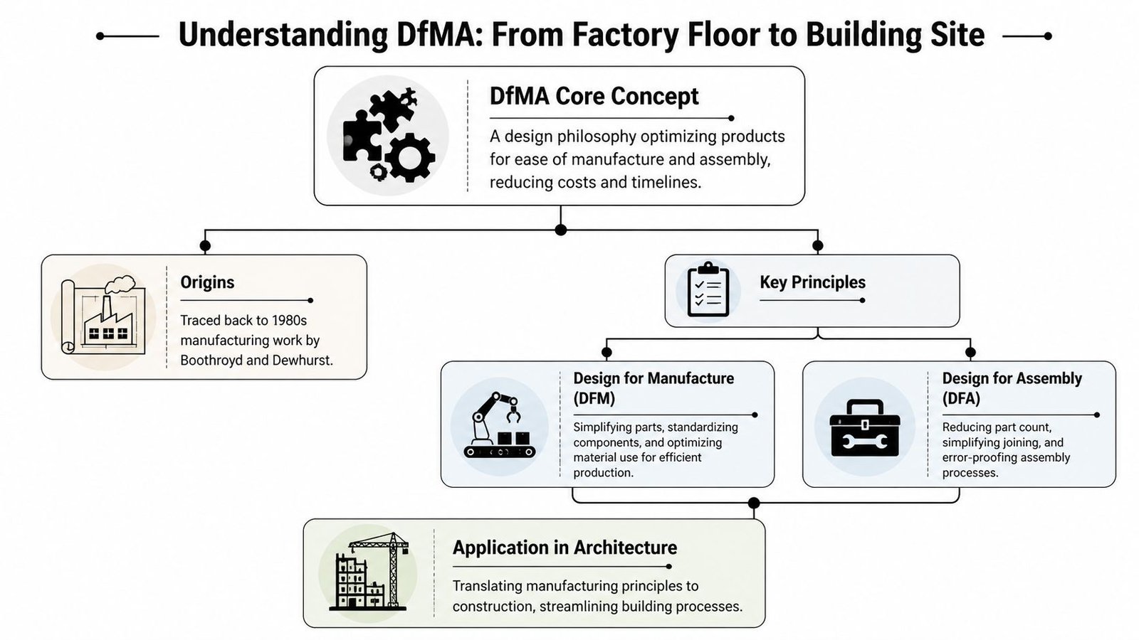
Understanding DfMA From Factory Floor to Building Site
A factory manager does not ask whether a crew can sort it out later. The line either runs, or it stops. That is the mindset behind DfMA, and it is why the method feels unfamiliar to teams used to resolving friction on site.
DfMA started in manufacturing. Boothroyd and Dewhurst built the method around a few plain questions. How many parts are necessary? How many separate handling steps can be removed? How can assembly happen in a predictable order, with fewer fasteners, fewer adjustments, and less opportunity for error?
That approach has a long track record in repeatable production. As summarized in the U.S. Department of Energy DFMA training module, DFMA case studies show the same pattern again and again: fewer parts, fewer separate fasteners, fewer assembly operations, shorter assembly time, and a much higher design-efficiency score when teams simplify the product before production starts. Construction borrowed that logic because the same waste shows up in buildings, just under different names. Extra part counts become extra types. Extra handling becomes extra lifts, extra site storage, and extra chances to install the wrong item in the wrong place.
Buildings are harder than consumer products. Site access changes. Planning grids shift. Consultants issue information at different speeds. Trade packages are split across contracts. Transport limits also set hard boundaries. If a volumetric unit is too wide for the route, the design is wrong no matter how good it looks in BIM. In many regions, once loads push past standard highway limits, escort requirements, route constraints, and delivery cost rise fast.
So DfMA in construction is not a borrowed slogan. It is a practical filter for design decisions from model to factory to crane hook to final connection.
What DfMA means in building terms
For architects, DfMA changes the job in four specific ways.
| Principle | What architects do differently |
|---|---|
| Reduce unnecessary variation | Limit unit types, rationalize bay sizes, repeat wall build-ups, and keep service zones consistent |
| Simplify assembly | Detail joints and handoff points so installation order is clear before fabrication starts |
| Design around logistics | Set assembly size, weight, and geometry with transport, lifting, and site access in mind |
| Push value into the factory | Move labor into repeatable assemblies that can be checked under controlled conditions |
Workflow changes become real in a BIM process. A repeated bathroom pod is not just a procurement choice. It affects the grid, riser positions, door swings, wall tolerances, MEP connection points, and how many model exceptions the team has to carry through coordination.
A practical example helps. If the façade panel width changes floor by floor to follow minor planning adjustments, the architect has created more than a drafting issue. The manufacturer now has more moulds or jig resets, procurement has more SKUs to track, QA has more opportunities for mismatch, and site crews have fewer interchangeable units when delivery sequence slips. The drawing still works. The production system works worse.
How the factory-floor logic translates to site work
On a building project, the DfMA test is straightforward. Can the assembly be made repeatedly, moved legally and safely, lifted without special workarounds, and installed in a predictable sequence with tolerances that match the model?
If the answer is unclear, the design is still carrying site-era assumptions.
That is why DfMA changes day-to-day architectural decisions. Corridor widths are checked against pod movement, not only code minimums. Structural openings are sized around actual plant and module routes. MEP zones are aligned so connections land in the same place every time. Tolerance strategy gets drawn, not left for a site meeting. Teams working through that shift usually benefit from seeing how off-site construction workflows affect design coordination and delivery planning.
The architectural translation
Architects usually need the biggest reset in four areas:
- Standardization has to be intentional: Three well-resolved room types usually outperform twelve near-matches that each need separate detailing.
- Assembly sequence belongs in design: If access for fixings, sealants, or final connections is awkward, the model is not ready for production.
- Interfaces stay with the design team longer than many assume: Pod-to-slab joints, façade anchors, riser penetrations, and rack supports need defined geometry early.
- Repetition has to survive design development: A scheme can start rational and drift into custom end conditions that wipe out factory efficiency.
DfMA works when the model describes something a factory can make repeatedly and a site team can install without interpretation.
A few habits still break projects. Late grid moves. Too many special corner conditions. Tolerance decisions deferred until shop drawing review. Highly detailed visual models with unresolved joints behind the finish line.
DfMA is the operating method that turns prefab from a product choice into a reliable delivery system.
How DfMA Redefines the Architectural Design Process
If you want a modular or prefab-heavy project to run cleanly, the design process has to change before the first serious round of plan iteration. This isn’t about adding one extra consultant meeting. It’s about changing which decisions get made early and which decisions are no longer allowed to drift.
Pre-design means locking the production logic
On a conventional job, pre-design often stays broad. Program, entitlement, high-level stacking, maybe early massing. On a DfMA job, pre-design needs sharper questions.
Before schematic design closes, the team should know which elements are intended for off-site manufacture. Bathroom pods. Wall panels. Structural cassettes. Corridor MEP racks. Façade assemblies. If that answer is still vague, the architect is designing without the project’s actual constraints.
The other change is who needs to be in the room. The factory, fabricator, or modular partner can’t be treated like a downstream bidder. Their assembly standards, preferred interfaces, repeatability limits, and production assumptions need to shape the design basis.
Field lesson: The earlier the manufacturer reviews the kit of parts, the fewer “design surprises” come back as premium-cost exceptions.
A useful checkpoint in pre-design is a short decision matrix:
| Decision | Must be known early | Why it matters |
|---|---|---|
| What is built off-site | Yes | Drives grid, interfaces, and consultant scope |
| What stays site-built | Yes | Defines handoff points and sequencing |
| How many repeatable module types are acceptable | Yes | Controls complexity and plant setup burden |
| Which party owns fabrication-level model inputs | Yes | Prevents gaps between design model and shop output |
Schematic design becomes a commitment phase
Most architects are trained to keep options open in SD. DfMA forces the opposite on a few critical items.
The planning grid needs to stabilize early. If the project wants repeatable wall panels, racks, or volumetric units, that grid is not a graphic convenience. It is the backbone of production. The same goes for floor-to-floor logic, riser strategy, and service distribution zones.
This is also the phase where repetition should be designed on purpose, not discovered by accident.
A strong SD package for design for manufacture and assembly prefab buildings usually does these things well:
- Reduces unique room types: Not every floor needs its own special condition.
- Fixes wet-core logic early: Bathroom and kitchen stacking should stop moving.
- Sets realistic assembly boundaries: Decide where the factory scope ends and field scope begins.
- Aligns structure with repeat modules: Don’t create avoidable partial bays or awkward edge pieces.
What doesn’t work is treating modularity as a future optimization. If the team says, “We’ll standardize later,” it usually means they won’t.
Design development carries more technical weight than usual
DD on a DfMA project is where many teams realize they’re behind. In traditional practice, unresolved interfaces can coast toward CDs and get pushed into RFIs, submittals, and field coordination. That won’t hold here.
By DD, the team should be resolving boundary conditions between architecture, structure, and MEP at the points where assemblies connect. Pod edge to corridor slab. Panel joint to primary frame. Rack support to structure. Stub-out position to riser zone. Those aren’t detailing leftovers. They are production-critical interfaces.
A good DfMA DD review asks harder questions than a standard design review:
- Can this assembly repeat without manual reinterpretation?
- Have we fixed the dimensions that control manufacturing?
- Are the connection types standardized or still drifting by location?
- Would a fabricator be able to derive production information from this model set without redesigning the intent?
If the answer to those questions is fuzzy, the package isn’t ready.
Construction documents move closer to fabrication intent
Traditional permit-oriented CDs often communicate compliance and general coordination. DfMA needs more precision.
That doesn’t mean the architect becomes the fabricator. It means the architect cannot issue a vague set and expect the factory to resolve core geometry, tolerances, or interface logic on its own. Production teams need clear dimensions, repeatable connection details, fixed opening conditions, and coordinated service locations.
Many teams feel the pressure of moving toward LOD 350 or even more fabrication-aware geometry at key interfaces earlier than they’re used to. The permit set may satisfy the authority having jurisdiction, but the production team still needs information the permit reviewer doesn’t care about.
The sequence really is inverted
Here’s the plain comparison.
| Traditional workflow | DfMA workflow |
|---|---|
| Explore plans first, rationalize later | Set production constraints first, then explore within them |
| Consultants can coordinate progressively | Interfaces need early cross-discipline resolution |
| Repetition is helpful but optional | Repetition is the economic engine |
| Shop drawing phase absorbs detail gaps | Detail gaps block production release |
That inversion is where many teams struggle. It feels restrictive at first because it limits late freedom. But that restriction is what creates predictability.
If a project depends on repeat manufacturing, schematic design is no longer the phase for loose intent. It’s the phase where you protect the entire downstream process.
For project architects, the practical change is less about theory and more about checkpoints. Freeze the grid sooner. Stop moving the wet stack. Define module families intentionally. Review interface zones with structure and MEP before DD drifts. Treat production drawings as the destination, not someone else’s cleanup exercise.
That’s what DfMA vs traditional construction really looks like in daily work. Less heroic rescue. More disciplined early decision-making.
DfMA in Practice Critical Decisions for MEP and BIM Workflows
Most architects first feel the pressure of DfMA in two places. The first is MEP. The second is the BIM model itself.
That’s not a coincidence. MEP systems are dense, layered, and intolerant of casual geometry. BIM is the place where those decisions either become repeatable or become expensive.
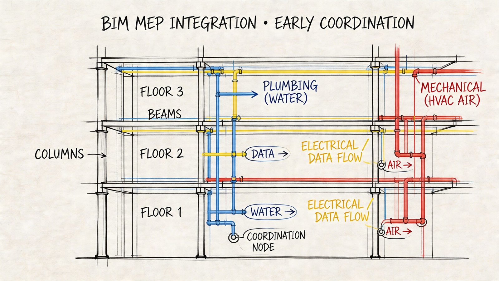
Why MEP exposes weak DfMA thinking first
Architects don’t size ducts or lay out final hydronic systems, but they absolutely shape whether those systems can be prefabricated cleanly. Ceiling plenum depth, corridor width, riser placement, wall thickness, shaft alignment, and wet-core consistency all come from architectural decisions.
Bathroom pods are the clearest example. A pod only works well when dimensions, connection points, and repeatability are stable. If every “same” bathroom has slightly different soffits, fixture offsets, or chase conditions, the pod stops being a repeatable product and becomes a set of custom rooms built in a factory.
The same problem shows up in corridor and ceiling prefabrication. Multitrade MEP racks depend on predictable routes and stable support geometry. If one floor changes section logic or introduces a local exception, the rack strategy can collapse into one-off fabrication.
A lot of firms still underestimate this because they think of MEP prefab as an engineering issue. It isn’t only that. It is also an architectural consistency issue. For teams working through those coordination demands, this overview of MEP systems production support is a useful companion.
The biggest MEP decisions architects control
Here are the decisions that usually matter most:
- Wet wall consistency: Repeated plumbing locations make pods and stacked utility strategies viable.
- Section discipline: Ceiling changes create routing changes, which create fabrication changes.
- Shaft and riser stability: Slight shifts from floor to floor break repeatability.
- Access logic: If maintenance or connection access is impossible after installation, the assembly isn’t fully resolved.
- Boundary ownership: Teams need to know exactly where pod scope ends and building scope begins.
A prefab MEP strategy fails long before fabrication if the architect keeps moving the spaces that define the routing envelope.
BIM has to carry manufacturing intent, not just design intent
Many firms are still underprepared. Standard BIM coordination workflows often stop at “clear enough to coordinate.” DfMA needs more.
A documented gap in the market is that most DFMA guidance explains principles but does not provide a practical framework for embedding them into BIM and parametric architectural workflows. That gap matters because case studies show cost reductions can exceed 50% when DFMA is applied early, yet many AEC teams still lack a way to run manufacturability checks across disciplines inside the model according to 6Sigma’s discussion of DFA in practice.
That aligns with what experienced delivery teams see in real projects. The model can’t just represent geometry. It has to support production decisions.
What changes in the model
A DfMA-ready model usually differs from a standard design-authoring model in a few ways.
Repeatable modules need controlled instances
Don’t let repeated units turn into hundreds of independent edits. If the project includes repeat bathrooms, patient rooms, hospitality keys, façade bays, or service zones, model them in a way that supports controlled propagation.
That may mean linked module files, disciplined group strategy, or tightly managed family logic. The exact method varies by project and platform. The principle doesn’t. A change to a repeatable unit should update predictably everywhere it is meant to repeat.
Interface zones need earlier precision
General layout geometry won’t carry a fabrication conversation very far. The places where assemblies meet need more exact information sooner.
That includes:
- Connection points
- Penetration locations
- Support conditions
- Clearance zones
- Stub-out and termination logic
Those areas usually need more mature coordination than the rest of the model by the end of DD.
Manufacturer content should shape the model where possible
If a fabricator has standard Revit families, preferred connection logic, or defined assembly libraries, use them. Rebuilding manufacturer logic from scratch often creates subtle mismatches between the design model and what the plant can produce.
BIM quality on a DfMA project is not cosmetic
On many conventional jobs, a model can still be “good enough” even if some elements are graphically neat but technically loose. That standard doesn’t hold when model geometry feeds coordination, takeoff logic, release sequencing, and fabrication interpretation.
The practical test is simple. Could the downstream team use this model to make a no-drama decision about production, or would they need a redesign meeting first?
If they need the meeting, the model is still carrying design intent, not production certainty.
The Biggest DfMA Mistakes and When to Use This Method
A project can look prefab-ready in Revit and still fail the moment the factory asks for a release package. The usual problem is not ambition. It is timing. The design team is still treating key decisions as adjustable, while the production team needs fixed geometry, repeatable details, and a clear sequence for what gets approved first.
That mismatch usually shows up in four places.
The mistakes that cost the most
Locking the structural grid too late
On a DfMA job, the grid sets more than planning geometry. It drives module widths, panel breaks, corridor alignment, bathroom stacking, riser positions, and what can move by truck. If a module has to stay within transport limits or a panel has to work with available lifting points, late grid movement affects far more than the drawing set.
Architects first feel the shift in workflow. In a conventional process, the grid can stay a live conversation deeper into design development. In a factory-led process, that flexibility runs out earlier.
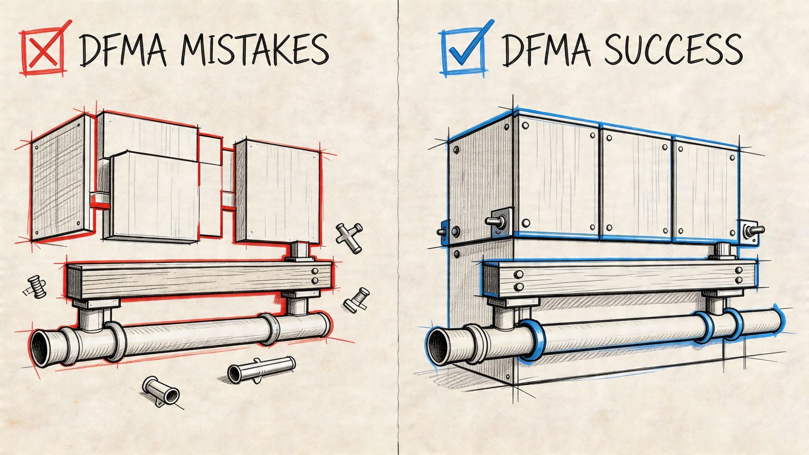
Designing too many special conditions
A one-off corner, an adjusted window head, or a slightly different wet wall may look minor in design review. On the production side, each one can mean a separate family, another shop detail, another QA check, and another chance for the site crew to install the wrong variation.
Repetition pays for DfMA. Exceptions spend that money fast.
Leaving MEP consequences to later coordination
Late changes to ceiling zones, shafts, plant space, and riser locations do not stay in the architecture model. They ripple straight into rack layouts, module boundaries, access panels, and service clearances. By the time the clash meeting catches it, the issue is no longer coordination. It is redesign.
Architects do not need to size the ductwork. They do need to hold steady on the spaces that ductwork depends on.
Treating the factory like a trade package
A serious prefab partner is setting production rules from day one. They care about repeatable dimensions, tolerances, lifting logic, fixings, storage, transport protection, and install sequence. If those rules arrive after planning approval or after major BIM content is built, the team has already burned time.
I have seen this happen on otherwise capable projects. The architect develops a clean concept model, the consultants coordinate around it, and the manufacturer then explains that two module types would build cleanly while the five drawn types create setup waste and a slower release cycle. That conversation needed to happen months earlier.
Why those mistakes cost real money
The loss is rarely abstract. It shows up as redraw time, delayed sign-off, more unique shop outputs, and site crews waiting on revised information. A factory gets its margin from repeatability and flow. Once the model keeps introducing exceptions, the plant starts carrying design risk it never priced for.
That is also why production teams put so much weight on drawing quality. A fabrication team cannot work from a model that still needs interpretation. If you want a useful benchmark for that level of definition, review this shop drawing example for fabrication handoff. It shows the difference between coordinated intent and information a production team can release with confidence.
When DfMA is the right method
DfMA works best when the project has enough repetition to justify earlier decisions and tighter rules. The strongest candidates usually have several of these conditions:
- Repeatable room or bay types: Multifamily, hotels, student housing, healthcare wards, and similar programs
- Clear value in parallel working: Site works and factory production can progress together
- An owner who wants predictability: Fewer variables matter as much as speed
- A team willing to standardize: Fewer type variations, fewer bespoke details, earlier sign-off
- Physical constraints that can be designed around early: Transport widths, cranage, storage areas, and installation access
Portfolio clients often get the most from it because the learning carries into the next job. The first project builds the rules. The next project starts with them.
When traditional delivery is usually the better choice
Some projects do not give DfMA enough repetition to pay back the front-loaded effort.
| Poor DfMA candidate | Why it struggles |
|---|---|
| Highly bespoke institutional work | Too many unique spaces and one-off details |
| Geometry driven by constant exception | Repetition breaks down |
| Projects with unstable scope | Early freeze points keep slipping |
| Teams with weak coordination habits | Production decisions arrive without the discipline to support them |
A hybrid approach often makes more sense on those jobs. Standardize bathroom pods, corridor services, plant skids, or façade zones where repetition is real, then keep the rest conventional. That is often a better commercial decision than forcing full modularization onto a building that does not suit it.
The better question to ask early
The useful question is not whether a project can use prefab. Almost any project can prefabricate something.
Ask these instead:
- Where is the repeatability that will survive planning, coordination, and procurement?
- Which decisions need to be fixed in SD or early DD to protect that repeatability?
- What is the manufacturer telling the team about transport, lifting, tolerances, and release sequencing?
- Will the owner accept fewer options in exchange for speed, certainty, or cost control?
If those answers are vague, DfMA will feel restrictive and expensive. If those answers are clear, DfMA becomes a disciplined way to reduce redesign, protect production flow, and give the architect a much firmer route from model to built work.
From Design Intent to Production Certainty
The clearest way to understand design for manufacture and assembly DfMA architecture is this. It asks architects to stop thinking only about what the building should be and start thinking about how the building will be produced repeatedly, with minimal reinterpretation.
That shift sounds narrow, but it changes almost everything important. It changes when the grid gets fixed. It changes how many unit types are acceptable. It changes how seriously teams treat MEP boundaries, BIM parameters, and repeatable details. It also changes how much risk gets pushed downstream into RFIs, late submittal churn, and expensive field correction.
DfMA is not a procurement label. It is a design discipline tied to production maturity.
Architects who understand that become more useful early. They ask better questions in pre-design. They keep schematic design from drifting into manufacturing problems. They give consultants and fabricators a model that supports execution instead of forcing redesign.
For firms building toward that level of delivery, examples of fabrication-oriented outputs help. A practical reference point is this shop drawing example workflow, which shows the kind of precision production teams need when design intent must turn into reliable assembly.
The teams that do this well don’t just deliver drawings. They deliver consistency, cleaner handoffs, and fewer surprises when the project leaves the model and enters production.
If your team is heading into its first modular, prefab, or DfMA-heavy project, BIM Heroes can help you set up the production logic early, from repeatable BIM modules and disciplined model structure to fabrication-ready coordination support. If you want a practical conversation, not a sales pitch, reach out and ask for a framework, checklist, or scope review.