


A restaurant TI can look clean on the coordination set and still die at health review because the kitchen hood exhaust package was treated like a single line item instead of a system. I've seen the same failure pattern repeat, a tight ceiling plenum, a grease duct that never got checked against structure, and a makeup air note that didn't prove balance. The GC thought the hood was “in.” The reviewer saw missing system data, and the schedule slipped into RFIs, rework, and a second round of submittals.
Kitchen Hood Exhaust Coordination Failure
The problem usually starts earlier than the first correction letter. Design hands off a hood layout that looks dimensionally right, then the permit set lands with a symbol, a few airflow notes, and no real proof that the exhaust, replacement air, and fire protection are being coordinated as one package. By the time the reviewer asks for the missing pieces, the team is already committed to equipment cuts, framing layout, and ceiling heights.
The cleanest way to avoid that stall is to treat the kitchen hood exhaust as a permit checkpoint, not an equipment selection. For restaurant TI work, that means the exhaust path, the makeup air route, the hood listing, the suppression interface, and the structural route all need to agree before submittal. If one of them is missing, the rest of the package looks provisional.
That's the production lesson here. A single uncoordinated hood can burn more margin than a dozen smaller coordination misses, because it touches architecture, mechanical, fire protection, and health review at the same time. If your team also wants the broader restaurant shell-and-core context, the design standards in this restaurant design resource are worth keeping close while you scope the hood package.
Practical rule: if a hood note can't survive permit review without a verbal explanation, it isn't ready for issue.
What Reviewers Look for in Exhaust Hood Drawings
Permit reviewers are not looking for a generic hood symbol and a fan tag. They want a matched system, with the hood tied to the cooking equipment, the exhaust fan, the makeup air fan, and the listing documentation that proves the assembly is legitimate. One public health plan-check sheet specifically requires manufacturer cut-sheets for the cooking equipment, exhaust fan, makeup air fan, and the UL listing card for the hood system so the reviewer can verify performance as a set, not as isolated parts (Sonoma County plan-check sheet).
The drawings need enough information for the reviewer to trace intent without guessing. That usually means hood face dimensions, plan location, section cuts, airflow callouts, duct routing, and the fire suppression interface. If the permit set shows the hood but doesn't show how it is listed, exhausted, balanced, and protected, the reviewer has every reason to send it back.
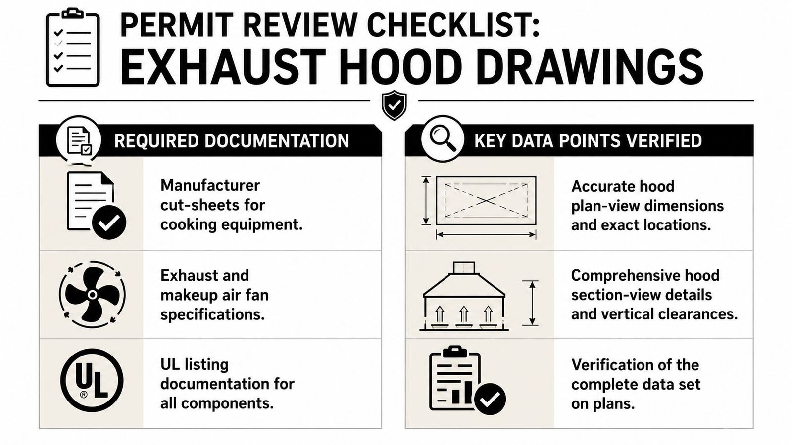
A useful way to think about it is this. The hood is not just a mechanical device, it's a documented air-quality and fire-safety system. That's why permit reviewers care about the complete data trail on the sheet set and not just the outline on the reflected ceiling plan.
For teams working in BIM, the checklist logic should live in the model and the sheet template together. A good starting point for that discipline is the permit drawings workflow resource, because the hood package fails or succeeds at the annotation level long before field install.
Comparing Type I and Type II Kitchen Hoods
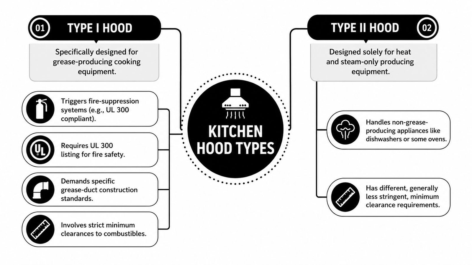
The first scoping mistake I see is teams treating every cooking area as if it needs the same hood logic. It doesn't. Type I hoods serve grease-producing appliances, while Type II hoods are for heat and steam only. That distinction drives the whole permit set, from the duct construction notes to whether fire suppression coordination is required.
Where Type I changes the drawing set
A Type I kitchen exhaust hood triggers the grease side of the conversation. For grease-producing appliances, a widely used code minimum is 200 CFM per square foot of hood face area for plume containment, which means the airflow discussion starts with actual hood geometry, not a generic fan tag (Enginist guide). That's the kind of number reviewers expect to see tied back to the layout.
Where Type II stays narrower
A Type II hood is still a permit item, but the documentation burden is different because the airflow and fire protection risks are lower than in grease service. The biggest mistake is assuming a heat and steam hood can be substituted into a grease duty line without revisiting the entire system. It usually can't, and that's where the RFI starts.
If you're checking elevations or cabinet integrations, it helps to visualize the full build early. A useful reference for that kind of pre-coordination is generate architectural renders with AI, especially when the ceiling plan and the equipment layout need to line up before shop drawings lock in the route.
CFM Calculations for Kitchen Hood Exhaust
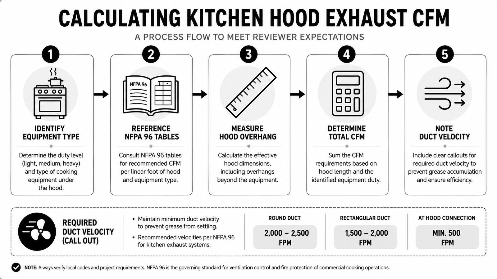
The airflow story has to be legible on the plans. Reviewers want to see how the exhaust value was chosen, how it relates to the hood geometry, and where the duct path sits in the overall assembly. NFPA 96 is the national standard for the design, installation, operation, inspection, and maintenance of commercial kitchen exhaust systems, including hoods, ducts, fans, and fire suppression (NFPA 96 overview).
What the sheet set should show
Don't leave the reviewer to reverse-engineer the airflow. The plan set should show the hood schedule, the equipment duty, the hood overhang or coverage intent, and the exhaust value called out in the same place. That's also where teams should note the effective opening area and the duct velocity zone so the system can be checked as a whole instead of as a loose collection of tags.
Why the calculation method matters
The airflow number is not just for code compliance, it drives noise, capture, and feasibility. A higher CFM value can look good on paper and still fail in the field if the hood geometry, appliance location, or duct routing undermine capture. That's why the mechanical sheet and the reflected ceiling plan need to agree before submittal, not after a reviewer asks for clarification.
If you want a simple way to keep the production discussion grounded, the impact of Cubic Feet per Minute is a useful primer to share with non-mechanical teammates who keep reducing the decision to “bigger fan, better hood.”
Coordinating Makeup Air for Exhaust Systems
A hood that exhausts air without a matching replacement path creates its own problems. In the field, that shows up as doors that fight the operator, a dining room that feels starved, and a reviewer who sees the imbalance immediately. The design check is straightforward, but it has to be documented, because makeup air is part of the permit scope, not a side note.
Replacement air needs to be drawn and labeled with the same care as exhaust, or the system reads as incomplete.
A DOE and ASHRAE kitchen exhaust guidance document states that replacement air introduced directly into the hood cavity must not exceed 10% of the hood exhaust airflow rate, and the compliance check should tabulate the short-circuit percentage for each hood (DOE and ASHRAE guidance). That threshold matters because short-circuiting air back into the hood defeats the point of the exhaust path.
What belongs on the permit drawings
The plan set should identify the makeup air fan, the discharge locations, the interlock logic, and the balance relationship to the exhaust fan. If the replacement air enters too close to the hood capture zone, the reviewer may flag the sheet even if the CFM values look nominal. If the system is in a tighter envelope, that note becomes even more important because the building pressure side effects show up faster.
This is one of the biggest RFI generators on restaurant TI work because the hood schedule is often issued before the final mechanical balance story is finished. The best teams close that gap in coordination, then send one coherent system to review instead of three disconnected disciplines.
Duct Routing and Structural Coordination
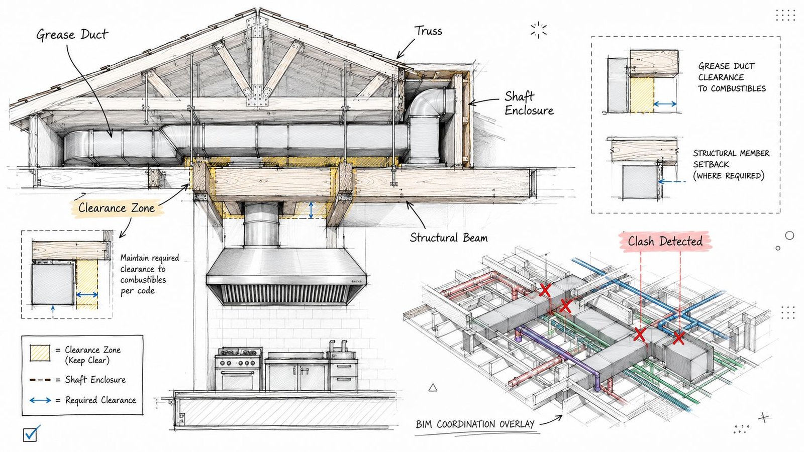
Grease duct routing is where the drawings stop being theoretical. A duct that works in plan may still fail when you drop it into joists, trusses, beams, or a crowded plenum. That's why the route has to be checked in BIM before the permit set goes out, not discovered when the framer or the duct installer is already mobilized.
The clash pattern that keeps repeating
The same three conflicts show up over and over. The duct wants the same corridor as a beam. The grease shaft lands where a truss pocket was assumed to be open. The plenum is too shallow once lighting, sprinkler mains, and the hood body are all modeled together. None of that is a surprise if the team runs a real coordination pass.
What the permit set should make obvious
The drawings should show the route, the enclosure intent, and the structural interfaces that need sleeves, offsets, or rerouting. Even if the final shop drawing is more detailed, the permit set has to prove the path is buildable. If that proof isn't on paper, the site team will end up resolving it with RFIs and field changes.
For teams formalizing that workflow, the duct design resource is a practical companion because it keeps the model-to-sheet transition focused on buildability, not just geometry.
Coordinating Fire Suppression for Kitchen Hoods
Fire suppression is where the hood package becomes life safety documentation. The suppression system has to match the hood type, the cooking equipment, and the listed assembly, and the drawing set needs to show enough for the reviewer to see that the coordination is real. The Minnesota regulatory guidance also requires kitchen hood fire-extinguishing systems to be serviced every 6 months, with dry chemical cylinders examined every 6 years and hydrostatically tested every 12 years (Minnesota guidance).
What belongs on the permit set
The permit drawings should identify the hood, the protected appliances, and the suppression interface points. The submittal usually needs to show nozzle locations, the general activation logic, and the access requirements so the system can be installed without conflicting with the hood body or the ceiling conditions. The exact shop layout is typically refined by the suppression subcontractor, but the permit set still has to show the design intent.
What should not be left vague
If the hood is shown without suppression coordination, or if the suppression notes don't match the hood and equipment schedule, the reviewer may assume the system is incomplete. That often becomes a correction cycle, then a field conflict, then a second submittal after the subcontractor has already priced the job. On commercial kitchen work, that's avoidable margin loss.
Common Documentation Mistakes to Avoid
- Missing CFM callouts. The reviewer can't confirm the exhaust basis, which usually triggers a mechanical correction.
- Unlabeled makeup air interlocks. The system reads as unbalanced, and the inspector may question whether the hood and replacement air operate together.
- Grease duct clearance omissions. Structural and fire-safety conflicts stay hidden until the coordination meeting or field install.
- Suppression notes left generic. The hood appears unprotected, so the package comes back for life-safety clarification.
- Fan schedules that don't match the hood. The reviewer sees disconnected component data and asks for a coordinated resubmittal.
- No listing documentation. A listed hood system can't be verified, which often delays approval.
Next Steps for Kitchen Hood Permits
Good hood documentation is a production maturity test. If the hood, exhaust fan, makeup air, duct route, and suppression package all line up on the sheet set, the project usually moves faster because the reviewer doesn't have to interpret intent. That same discipline helps restaurant operators too, especially when they're comparing build options in the early planning stage, the kind of planning covered in this essential guide for prospective caterers.
If your team is building commercial kitchen permit sets and wants the hood package checked before it becomes an RFI trail, bring the templates, schedules, and coordination details into one review. BIM Heroes can help tighten that package so the drawings are clearer, the review path is cleaner, and the project has a better shot at staying on schedule.
A CTA for BIM Heroes.