A clean Revit phasing view can still fail in the field. I've seen a hospital renovation sail through internal coordination, only to stall when the fire marshal asked where the temporary egress path was during a demolition-and-new-construction swap, and nobody could show a clear, phase-specific answer on the sheet. The model looked right. The construction phasing plan did not. That gap is exactly where occupied renovations get expensive, because the GC needs a sequence that can be built, the reviewer needs life-safety continuity, and the field team needs a plan that doesn't change with every coordination meeting.
If you want the graphic side first, the earlier BIM Heroes post on Master Revit Phase Filters: Demolition & New Construction is the right companion piece. Phase filters are necessary, but they're only the display layer. The deliverable that survives review is the sequencing and coordination package behind them.
When a Clean Revit Model Fails in the Field
A school renovation can look polished in Revit and still break down the moment occupied-phase logistics get real. The plans may show demolished partitions, new walls, and future work with tidy visibility settings, but the field superintendent is asking a different question. Where do kids exit while the west corridor is under construction, and what barrier keeps the work area separated while that route stays open?
That's the kind of miss that gets a phasing sheet kicked back. It usually happens when the team treats the model as the deliverable instead of the sequence. The drawings may be graphically correct, but if a temporary path, a rated separation, or a shutdown window isn't explicit, the GC can't rely on it and the AHJ won't approve it.
Practical rule: if a phase changes how people move, exit, or stay protected, it needs to be visible on the sheet, not just understood in a coordination meeting.
In occupied hospital and school work, the problem is rarely that the team forgot Revit phasing. The problem is that the document answered the visual question and ignored the operational one. The fire marshal, the owner, and the contractor all read that gap immediately. A good construction phasing plan closes it before it reaches the field.
Phase Filters Are Not a Construction Phasing Plan
Phase filters control what appears as existing, demolished, new, or temporary in a Revit view. That is the graphics layer, and it matters. The earlier discussion of Revit phase filters covers that setup side well enough, so there is no need to repeat it here.
The bigger mistake is assuming the view itself constitutes the plan. A true construction phasing plan is a sequencing and coordination document that tells the GC what happens first, what must stay live, what changes at each gate, and what conditions must exist before the next phase starts. That is why the legal framing matters, too. Under CDM 2015, a construction phase plan is required on construction projects, and it must be in place before work starts on site, with the principal contractor or sole contractor responsible for producing it. Go Construct's overview of the construction phase plan is useful because it makes the compliance side plain.
The same document also needs to describe the health and safety arrangements, site rules, emergency procedures, welfare facilities, and how significant risks will be controlled during construction. Safety Clarity's summary of the construction phase plan lays out those core contents clearly, and HSE guidance says it should identify the main dangers on site, name the person responsible, and explain how supervision will be provided. HSE CIS80 reinforces that this is operational, not decorative.
A model can look coordinated and still fail that test. If it does not tell the contractor how to build safely through the phase boundary, it is not enough.
Defining Revit Phases That Match Real Construction Sequencing
Start with the GC's logic, not the model browser
A phasing structure should mirror the actual construction sequence, not a generic list of “existing” and “new.” On a real project, that usually means phases are tied to milestones, access changes, demo completion, rough-in releases, inspections, or turnover points. If the GC is planning work in a different order than the model, the sheet will drift out of sync before it reaches permit.
I prefer to build phases from the contractor's dependency logic, then map the Revit setup to that logic. That keeps the document aligned with the way crews move through the building. It also makes it easier to explain the sequence to reviewers, because each phase has a start condition, a finish condition, and a gate that releases the next scope.
For anyone tightening up that logic, understanding the critical path method is a useful refresher. It's not a Revit topic, but it helps frame why one delayed predecessor can cascade through the rest of the sequence.
Name phases so the sheet can be read in the trailer
Phase names should be short, descriptive, and consistent across plans, legends, and notes. “Phase 1” tells me almost nothing. “Phase 1, north wing demo complete” or “Phase 2, classroom tie-in and life-safety transfer” gives the GC something usable. That naming discipline matters on sheet sets because people rarely open the model when they're standing in the field or reviewing PDFs during a permit resubmittal.
Here's the discipline that holds up best:
- Build around milestone logic. Use phase breaks that match actual handoff points, not arbitrary graphic changes.
- Tie phase names to sheet language. If the note says “temporary corridor open,” the phase should say something equally explicit.
- Use separate models only when coordination demand justifies it. Most projects need cleaner phase mapping, not more model sprawl.
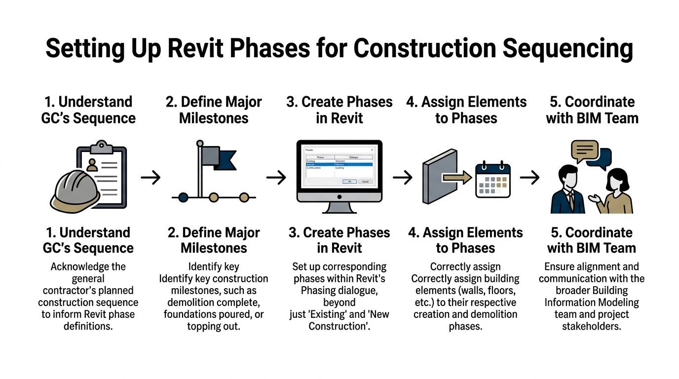
The strongest phasing plans are dependency-driven. If a wall can't go in until utility work and access control are complete, the sheet should reflect that order, not just the graphics.
Documenting Temporary Conditions and Life Safety Across Phases
Temporary life-safety items need their own language
Occupied renovation phasing lives or dies on temporary conditions. If part of the building stays open, the sheet has to show how people still get out, how the building stays separated, and how services stay alive long enough for the next phase. Temporary egress paths, temporary fire-rated separations, and temporary utility connections should be clearly modeled or annotated so the GC can build them and the reviewer can verify them.
That opening hospital miss I mentioned usually traces back to one of two failures. Either the team assumed the temporary corridor was obvious, or the route was buried in a note nobody could find in review. Both fail the same way in the field. The fix is to show the temporary path directly on the phase plan, tag it consistently, and tie it to the phase number so the reviewer doesn't have to infer anything.
Coordinate early with the AHJ, not after comments arrive
Fire marshals and other AHJs care less about pretty graphics than about continuity. They want to know that occupants and workers can move safely through each transition, and that the separation strategy isn't relying on assumptions. Standard icons, a tight legend, and phase-specific notes help a lot, especially when the work stays active around live use areas.
The operational details belong on the sheet, not just in coordination minutes. That includes temporary emergency lighting, signage, smoke barrier substitutions where applicable, and utility reroutes that support the occupied zone while the work zone changes. For temporary egress specific issues, the BIM Heroes article on egress path coordination is a good companion reference.
A strong plan usually keeps the visual code simple:
- Temporary routes should read differently from permanent circulation.
- Rated separations should be obvious enough that no one mistakes them for construction fencing.
- Utility changes should be tagged to the phase where shutdown and tie-in happen.
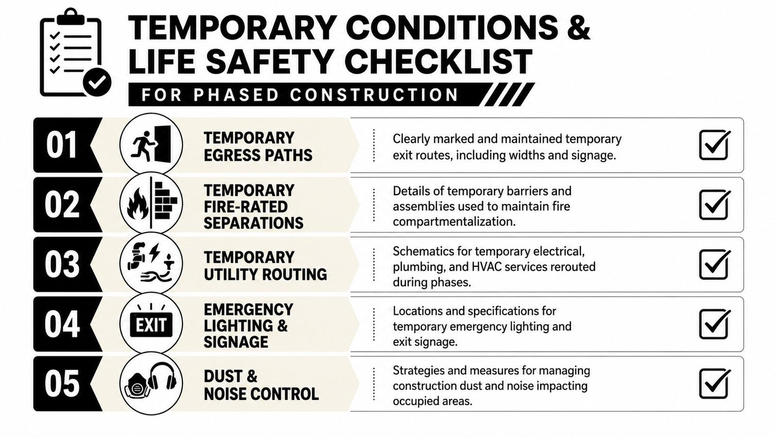
If the plan can't answer how life safety continues between phase boundaries, it's not ready for review. That's the standard I'd hold on any occupied renovation.
Coordinating Phasing Plans with MEP and Structural Sequencing
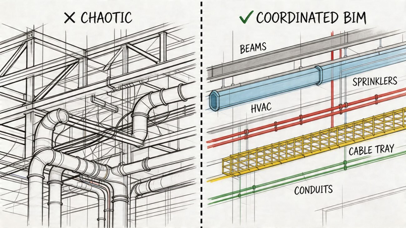
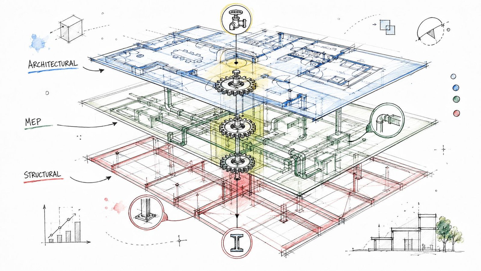
Architectural phasing breaks down fast when MEP shutdowns and structural work aren't aligned to the same phase structure. A wall demo can be perfectly sequenced in the architectural plan and still be impossible in the field if the electrical shutdown, duct reroute, or structural support condition hasn't been coordinated. That's how trade stacking starts.
The common failure is finalizing the architectural phasing plan first and asking consultants to “match it.” By then, the architecture has already locked the phase logic, and the MEP or structural team has to force-fit their work into a sequence that doesn't match field reality. Rework follows, then change orders, then a round of comments nobody has time for.
Pull consultants into the same gate structure
The cleanest workflow is to define phase boundaries once, then assign each discipline to the same boundary. If the architectural team says a corridor is demo-ready, the MEP team should already know when the related shutdown occurs, and the structural team should know what gets removed or reinforced before the next release. That doesn't mean every discipline draws the same thing. It means they all reference the same phase gate.
For complex jobs, the phasing plan becomes a coordination index as much as a drawing set. It should point the GC to the structural sequence, the utility tie-ins, and the temporary service strategy without making anyone hunt through a dozen sheets. The BIM team's job is to keep those references stable and make sure the drawings don't drift when one discipline updates its side.
The other useful habit is to document utility shutdown windows and temporary connections directly in the phasing notes. That gives the PM and superintendent a clear clue about when the work can happen, which is a lot more useful than a diagram that only shows end states. The article on MEP systems coordination is worth reading alongside this if your projects regularly involve occupied tie-ins or phased shutdowns.
What a Phasing Plan Sheet Must Communicate to Reviewers and the GC
A good phasing sheet isn't overloaded. It's readable, specific, and hard to misinterpret. If the reviewer can't tell where one phase ends and the next begins, the GC can't build from it, and the sheet hasn't done its job.
The practical checklist is straightforward:
- Clear phase boundaries. Use graphics that distinguish each construction zone and show where the boundary shifts.
- Legend that clearly explains the drawing. Existing, demolition, new, future, and temporary conditions should all be distinct.
- Temporary life-safety elements. Show the routes, barriers, signage, and any temporary protection that keeps the occupied zone usable.
- Sequencing notes tied to phase numbers. The note should say what happens in Phase 1, Phase 2, and so on, not just describe the project in general terms.
- Cross-references to MEP and structural sheets. Reviewers should know where the tied-in work lives without guessing.
If the sheet set has multiple phases, I'd rather see a clean, deliberate organization than a cluttered attempt to put everything on one page. One phase per sheet is often the safest path for occupied work because it reduces ambiguity. Multiple phases on one sheet can work, but only when the delineation is obvious and the legends are disciplined.
Good Revit view templates help a lot here because they keep graphic conventions consistent across sheets. That consistency is what makes the set feel coordinated instead of assembled. The best phasing sheets read like field instructions, not like a filtered view somebody printed because the deadline was close.
Common Phasing Plan Mistakes That Trigger Corrections or Field Conflicts
If you're trying to improve construction document processes across renovation work, the article on construction document management software is a useful lens for the larger workflow. On the phasing side, these are the mistakes that most often cause friction:
- Temporary egress is missing. The consequence is a life-safety comment, a rejected phase, or a field workaround that nobody wants to own.
- Architectural phases don't match MEP shutdowns. The consequence is tie-in conflict, idle crews, and avoidable rework.
- Phase transitions are vague. The consequence is the GC can't tell when the next area is released, so sequencing stalls.
- The legend is unclear. The consequence is reviewers and supers read the same graphic differently.
- The plan is treated as static. The consequence is the sheet set falls behind scope changes and stops matching the job.
- Temporary conditions are buried in notes only. The consequence is the field team misses them when they need them most.
BIM Heroes produces coordinated phasing plans as part of complex renovation and multi-phase CD sets, especially when the work has to hold up in occupied buildings. If you need a sharper sequencing package, a cleaner set of phasing sheets, or help turning consultant markups into something the GC can build from, visit BIM Heroes and book a call.