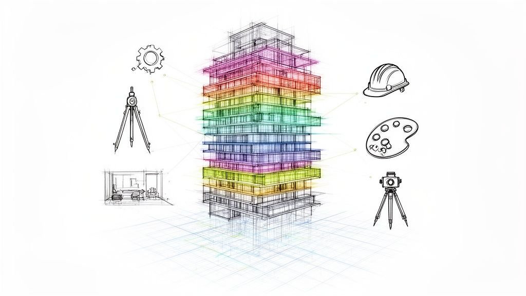
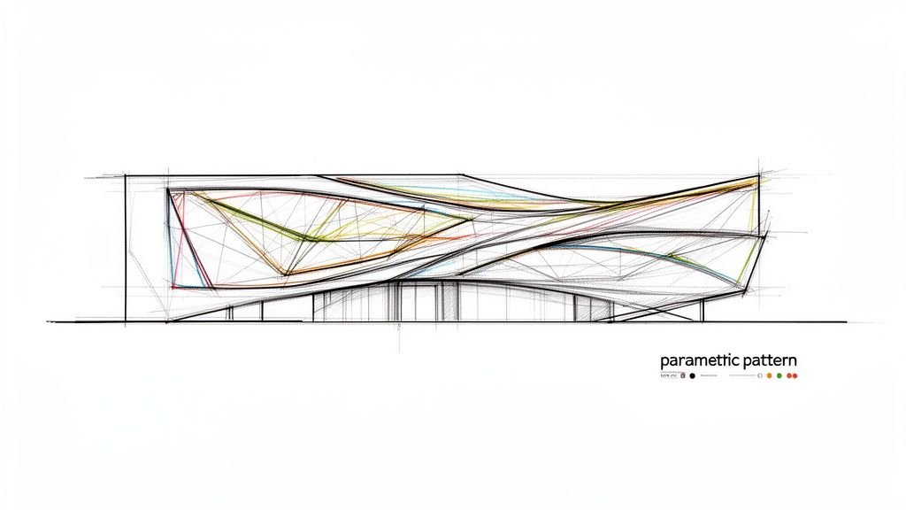
Building facades have become one of the most expressive and technically complex elements in contemporary architecture. Skins that would have been impossible to design—let alone build—twenty years ago are now being realized on projects of all scales. This is driven by the intersection of parametric design tools and BIM-driven fabrication workflows.
But there's a gap many firms encounter: the parametric model that generated the facade geometry and the BIM model that needs to document it for construction are often two different things, maintained by two different workflows. Reconciling them is harder than it looks. This isn't about a lack of vision; it's a breakdown in production discipline that erodes margins and predictability.
The lesson learned in the field is that parametric facade design has genuinely expanded what architects can conceive and what fabricators can build. But realizing that potential requires understanding how parametric geometry moves from design tool to construction document, and where that translation breaks down. This is how you prevent RFIs, protect margins, and deliver clarity instead of just hours.
What Parametric Facade Design Actually Means
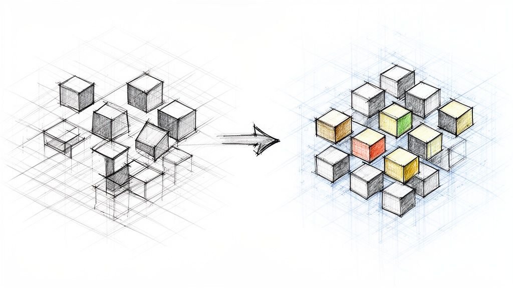
Let’s define this clearly, because a crisp definition sets up the rest of the workflow. Parametric design means using algorithms and rule-based relationships to generate geometry rather than drawing it manually. You change a parameter—and the geometry updates accordingly.
In facade design specifically, parametric tools allow architects to define rules that govern how facade elements like panels, fins, or louvers respond to conditions like solar angle, structural grid, or the curvature of the building form. The result is a facade where complexity is managed through logic rather than manual repetition. A facade with 3,000 uniquely sized panels is no more difficult to generate parametrically than one with 300 identical ones.
The key tools in this space include:
- Grasshopper running on Rhino
- Dynamo running inside Revit
- Increasingly native parametric capabilities within BIM platforms themselves.
The distinction between parametric design and BIM is critical for production maturity. Parametric tools excel at generating complex geometry; BIM tools excel at documenting, coordinating, and managing building information. For a parametric facade to become a built building, the two need to work together through a disciplined, predictable process. For more on this, see our guide on what parametric modeling is.
What Parametric Tools Are Making Possible in Facade Design
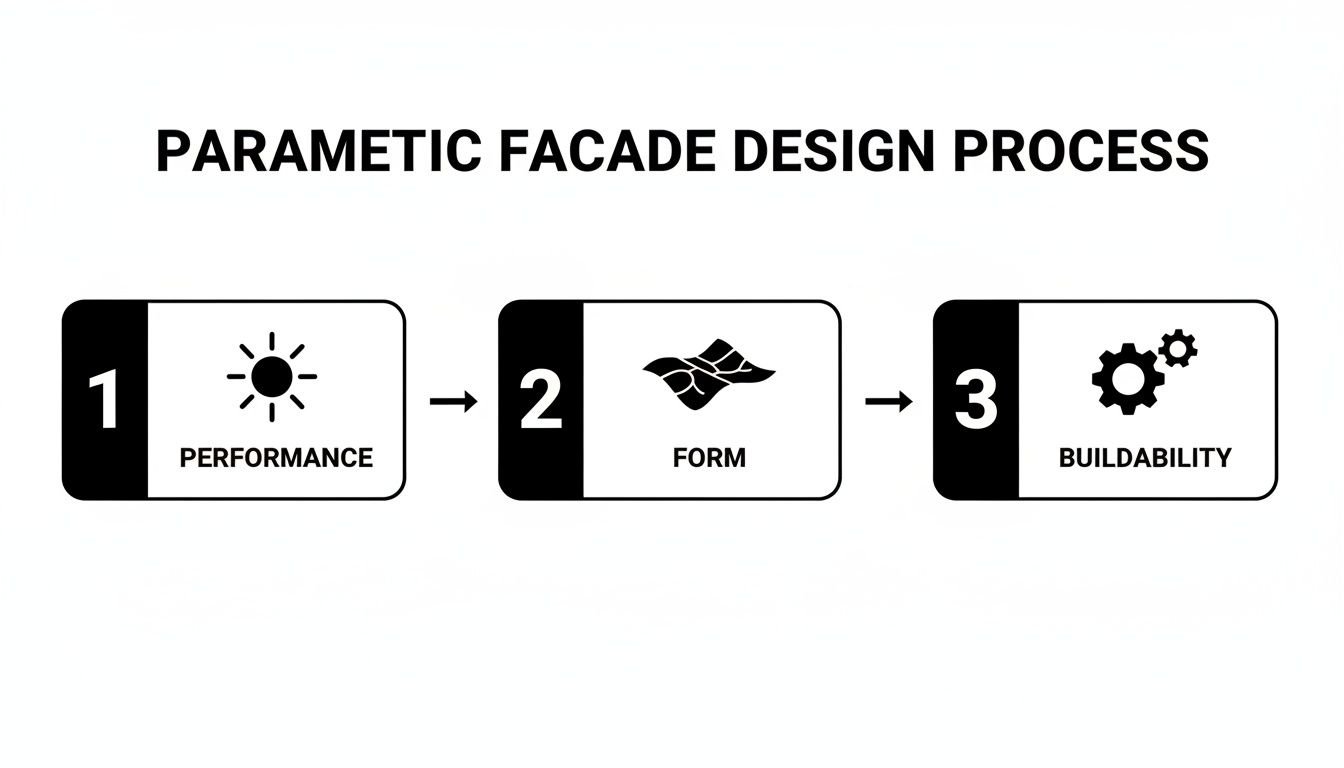
Parametric tools let architects blend performance with aesthetics in ways that were previously unfeasible. Instead of endless manual adjustments, you’re using logic to drive the design, making even the most intricate, high-performing facades achievable. This is where data-driven rules become architectural art.
Solar-Responsive Facades
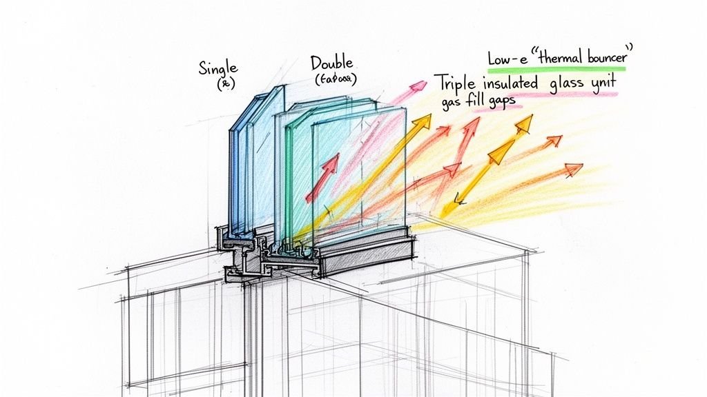
With a parametric workflow, fin angles, louver depths, or panel perforation patterns can be driven by solar analysis data. Each element is algorithmically optimized for its specific orientation and position on the facade. The result is a facade where performance and aesthetics are genuinely integrated. Without parametric tools, individually optimizing thousands of facade elements would be impossibly labor-intensive. This is especially true as the market for high-performance facades grows, a trend you can explore in this report on global facade market data and its growth drivers.
Complex Curved and Doubly Curved Surfaces
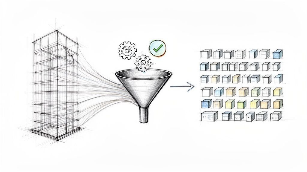
Facades that follow complex geometric forms—twisted towers, free-form cultural buildings—require parametric rationalization to become buildable. Parametric tools can take a complex surface and rationalize it into flat or single-curved panels that can be fabricated from standard sheet materials, a process called panelization. The same tools can optimize panel layouts to minimize the number of unique panel sizes, a key step in margin protection.
Patterned and Perforated Facades
Parametric tools allow pixel-mapped images, gradient patterns, or algorithmically generated patterns to be applied to facade panels with precise control over perforation size, spacing, and density. These patterns can even respond to structural requirements, like reducing perforation density near connections, while maintaining visual continuity.
Kinetic and Responsive Facades
Facades with moving elements—operable louvers, rotating panels—use parametric logic to define how elements respond to environmental conditions. A key part of the QA process is ensuring that BIM coordination for these kinetic facades documents both the static and dynamic states of the facade to prevent clashes.
Modular Systems with Controlled Variation
Parametric tools also allow designers to work with modular panel systems where variation is controlled—creating panels that are similar but not identical. This creates visual richness without the chaos of unmanaged fabrication complexity, supporting the kind of operational consistency that scalable delivery pods rely on.
The Gap Between Parametric Design and BIM Documentation
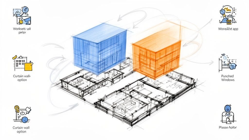
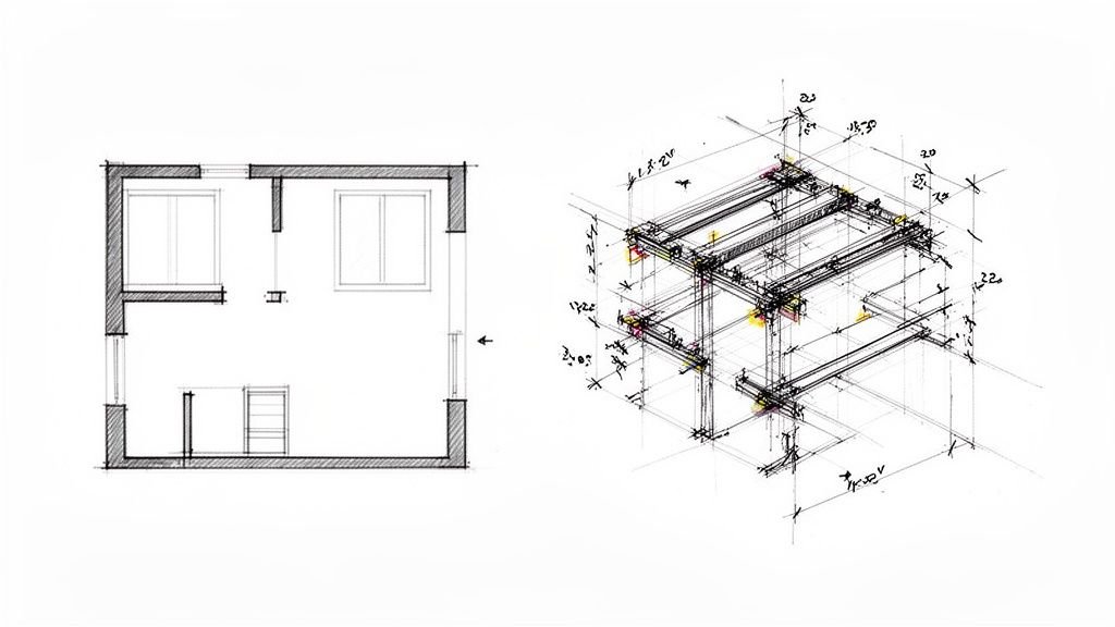
This is the most important section for any firm serious about production maturity. The core challenge is the ‘Two Models, Two Workflows’ problem. Creative designs often take shape in tools like Rhino/Grasshopper, but the construction documents and coordination live in BIM platforms like Revit. This disconnect is a major threat to margins and predictability.
The Translation Problem
When a parametric facade is imported into Revit as a mesh or generic form, it becomes a visual representation rather than a coordinated building element. This is a common failure point. Individual panels can't be scheduled, tagged, or dimensioned individually, which means the fabrication documentation can't be generated from the model. The only reliable solution is to rebuild the parametric geometry as actual Revit elements—families, curtain panels, adaptive components. It's labor-intensive but necessary for proper documentation.
Data Loss in Translation
Parametric models often carry rich performance data—solar analysis results, structural outputs, panel rationalization data—that gets lost when only geometry is imported into BIM. A lesson learned from the field: parameters that drove the design, like fin angle or perforation density, must be embedded as BIM parameters if they're going to appear in schedules and fabrication documents. Preserving this data requires deliberate workflow design.
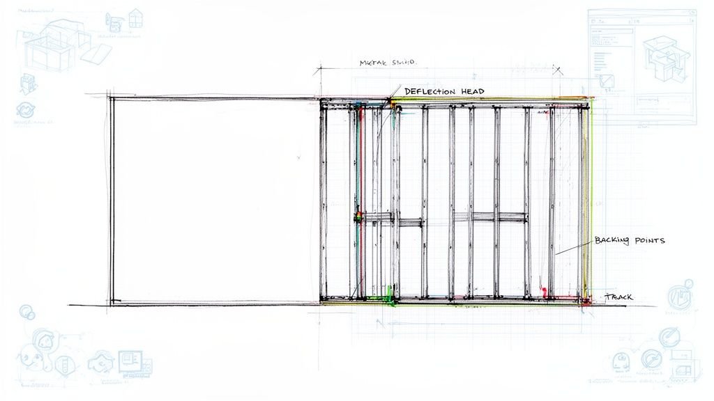
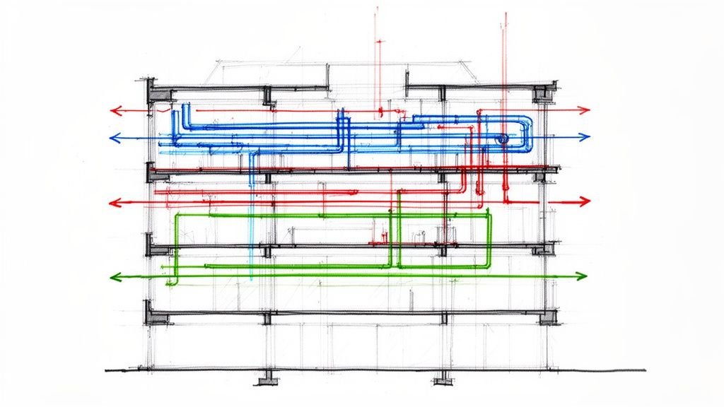
Coordination Consequences
A parametric facade that exists only as dumb geometry in the BIM model can't be clash-detected properly against structure or MEP. Anchor points, attachment hardware, and substrate framing must be modeled as real elements to identify conflicts before they become expensive field problems. This is where many parametric facade projects encounter surprises that could have been prevented with better BIM coordination and established decision checkpoints. The facade geometry was beautifully resolved, but its connection to the building was never properly coordinated. This is the definition of a failed CAD-to-BIM process.
Rationalization: Turning Design Geometry Into Fabricatable Components
Rationalization is the critical process of taking a complex design surface and breaking it down into components that can actually be manufactured and installed. This isn't about simplifying the design; it's about making it buildable and protecting the project's margin.
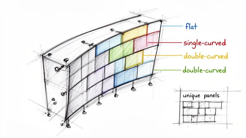
For panel systems, rationalization means identifying which panels are truly flat, which require single curvature, and which require double curvature, because fabrication cost increases dramatically with geometric complexity. Parametric tools can optimize panel layouts to maximize the number of flat panels while maintaining the visual character of the design—a process that can significantly reduce fabrication cost. This is a crucial step for hitting budget targets in a market where prefabricated facades are gaining traction. You can learn more about the drivers of the facade market here.
Rationalization also involves defining the structural logic of the facade—where the primary supports are, how panels attach to them, and how the attachment system accommodates thermal movement and construction tolerance.
The output of rationalization is a model-driven panel schedule. This schedule lists every unique panel with its dimensions, geometry type, finish specification, and position on the facade.
This panel schedule is one of the most important fabrication documents for a parametric facade design and one of the most difficult to produce accurately without a properly structured BIM model. Getting it right is essential for a clean set of shop drawings. You can see what goes into this level of documentation by checking out a comprehensive shop drawing example.
Documentation Requirements for Parametric Facades
When a facade is parametrically generated, the construction documents must be exceptionally clear and system-driven. Here is what they need to show:
- Overall facade layout drawings showing panel grid, panel IDs, and primary attachment points, all generated from the model, not manually drafted.
- A model-driven panel schedule listing every unique panel type with dimensions, area, finish, and quantity to ensure accuracy and prevent RFIs.
- Typical attachment details showing how panels connect to the substrate framing system, designed to work for the range of panel geometries.
- Atypical conditions—corners, edges, transitions—detailed individually as part of a rigorous QA process.
- Structural attachment layout showing anchor point locations on the building structure, with loads clearly communicated to the structural engineer.
- Thermal movement accommodation shown in the attachment details, which is critical for large metal panel systems.
- Installation sequence diagrams for complex facades where the order of panel installation matters and must be coordinated with the erection methodology.
This level of documentation is key to preparing for permitting and ensuring a smooth handoff to the fabricator.
How Dynamo and Grasshopper Bridge the Gap
How do you connect the parametric design and BIM documentation workflows in practice? Visual programming tools like Dynamo and Grasshopper-to-Revit connectors bridge this gap, automating the translation from concept to production.
Dynamo in Revit
Dynamo is Revit's native visual programming environment. It allows users to write scripts that automate repetitive modeling tasks, generate geometry based on rules, and extract data. For parametric facades, Dynamo can be used to place Revit families at parametrically defined locations, populate panel schedules with data, and automate the creation of attachment point geometry. The advantage is speed and accuracy—changes to the parametric logic propagate through the Revit model systematically, not manually. Check out our guide on mastering Dynamo scripts for Revit for more.
Grasshopper to Revit Workflows
Tools like Rhino.Inside.Revit are even more powerful, allowing Grasshopper scripts to run inside Revit and generate native Revit geometry. This allows the parametric logic that generated the facade design to drive the BIM model directly, maintaining a live connection between design intent and construction documentation.
The limitation is that these workflows require significant technical expertise to set up and maintain; they are not plug-and-play. This is where template discipline and an experienced production partner become invaluable.
How BIM Heroes Supports Parametric Facade Documentation
BIM Heroes supports architects working on parametric facade projects who need production documentation that matches the sophistication of their design. We sell clarity, systems, and reliable delivery—not hours.
Our team has deep experience translating complex parametric facade geometry into coordinated Revit models. We rebuild complex geometries as schedulable, coordinatable BIM elements, not imported meshes. We are familiar with Dynamo-driven workflows for panel schedule generation, attachment point documentation, and facade layout drawings.
We understand the coordination requirements between parametric facade geometry and structural attachments—not just the visual model, but the buildable assembly behind it. This includes robust BIM coordination services to ensure anchor points and panel geometry don't conflict with structure or building systems.
We work as an embedded production partner, staying involved through the entire CAD-to-BIM translation from parametric model to construction document set. This is how we provide the operational consistency that scalable delivery pods depend on.
Closing / Takeaway
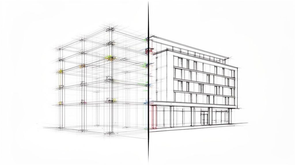
Parametric tools have genuinely expanded what architects can design. But the buildings that successfully realize these designs are the ones where the team invested as much rigor in the translation from parametric model to construction document as they did in the generative design itself.
The gap between a beautiful parametric model and a buildable, documented facade is where many projects lose ground—in cost overruns, fabrication errors, and coordination failures that could have been caught earlier with proper decision checkpoints and QA processes.
As parametric facade design becomes more mainstream and fabrication technology advances, the firms that build strong BIM documentation workflows around their design processes will deliver complex facades more reliably and profitably. They will be the ones who prove they understand production better than most. The market for high-performance buildings is growing—you can read the full research on the facade market's trajectory to see the numbers. The lesson is clear: treating documentation as an afterthought is no longer a viable option.
Working on a project with a parametric or geometrically complex facade? Let's talk about how BIM Heroes can support your facade documentation and BIM coordination workflow.