


A city reviewer asks for a photometric study, the site plan is already in circulation, and the fixture package has been ordered. That's when the project stops being about “better lighting” and becomes about whether the submittal package can prove footcandles, uniformity, and light spill where the jurisdiction cares about them.
On a real plan check, the comment is usually blunt. Show the property-line numbers, reconcile the fixture schedule, and prove the study still matches the drawings after the inevitable substitution. If the team can't do that fast, the approval slips even though the design itself may be fine.
A photometric calculation is the point-by-point math behind that proof, but the deliverable the reviewer wants is usually a photometric plan inside the drawing set. The calculation shows the values. The plan packages those values in a way the AHJ can read, compare, and approve.
What Photometric Calculations Actually Produce
A stalled site approval usually starts with one sentence in a comment letter, the city wants a photometric study at the property line. That doesn't mean the architect needs a lighting lecture, it means the submittal needs a defensible point-by-point illuminance calculation using fixture photometric data, typically from an IES file.
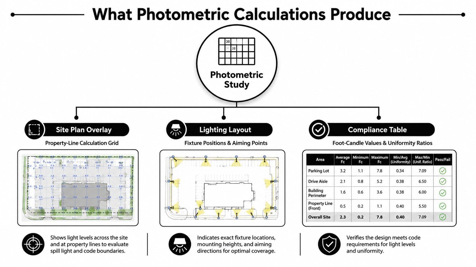
What the study is really verifying
The output is more than a pretty rendering. A real photometric study checks the numbers that matter to a reviewer, light levels, uniformity, and spill control against code or local criteria. Historically, that kind of comparison has always mattered because lighting started as a way to compare luminous output objectively rather than by eye, from Bouguer's early comparative photometer work in 1729 and Rumford's practical lamp comparisons in 1792, then moving toward reproducible science by the 1830s and standardized light-intensity references by the 1930s (historical review).
That history still shows up in production today. The software may be digital, but the logic hasn't changed, compare the source data, model the geometry, and prove the result on a calculation grid.
What the package usually includes
A complete submittal package normally has a photometric site plan, a fixture schedule, cut sheets, and a calculation summary. If one of those pieces is missing, the reviewer has to guess, and guessing is where comments start. If you're checking whether the package is complete, the easiest test is simple.
Practical rule: if the plan can't be traced back to the exact fixture, mounting height, and target plane, the study isn't complete enough for permit.
The calculation and the plan are related but not identical. The calculation is the math, the plan is the drawing artifact that carries that math into the permit set.
When a Jurisdiction Requires a Photometric Plan
Most firms only learn the trigger after a reviewer asks for it. The fastest way to avoid that surprise is to identify which approval path is driving the requirement, because the answer changes depending on whether the issue is zoning, egress, energy, or owner criteria.
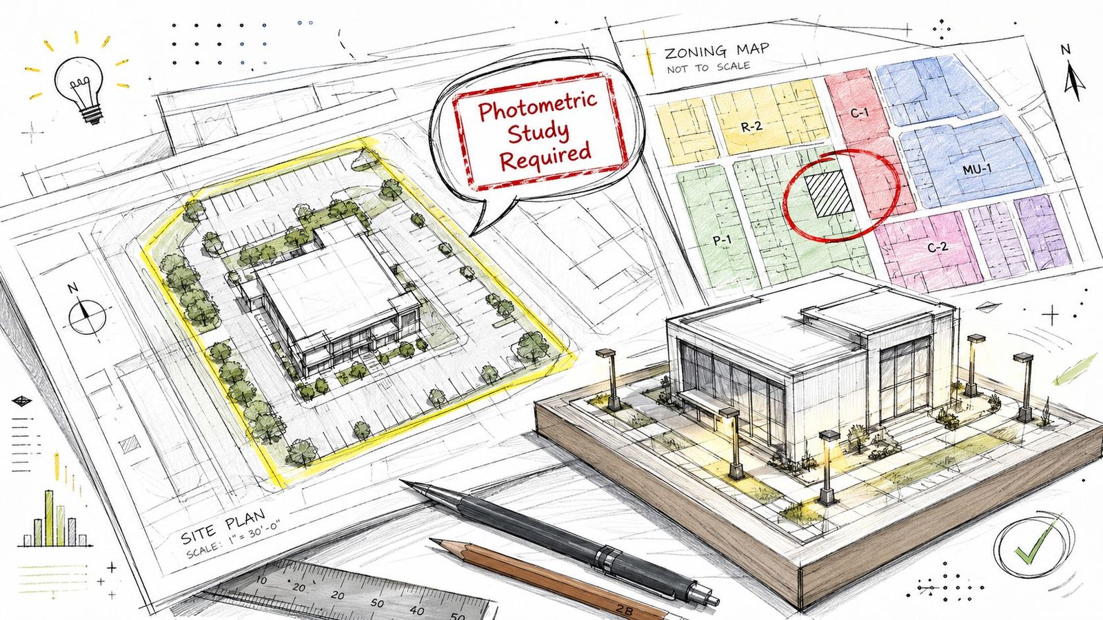
Use this permit drawing coordination reference when the lighting issue is tied to the broader submittal set.
The four common triggers
Zoning and site plan approval is the most familiar one. Parking lots, exterior entries, and façade lighting often get reviewed for property-line spill, dark-sky language, and nuisance control, especially where local amendments tighten the rules beyond the base code.
Egress lighting comes up when the reviewer wants proof that the path of egress stays lit during normal-power loss conditions. The IBC commonly drives a target around 1 fc average along the egress path, but the exact requirement can vary by adopted edition and local amendment, so the calculation has to mirror the jurisdictional text rather than a generic template.
Energy code compliance is another path. Under IECC and ASHRAE 90.1, the reviewer may be looking at lighting power density and fixture selection, not just illumination. That means the photometric package has to align with the energy narrative, or the submittal looks split-brained.
Owner, insurer, or project-specific criteria show up even when the AHJ doesn't ask first. Private development teams, campuses, and risk managers often want a paper trail showing the lighting was checked intentionally, not guessed.
What to quote back to the reviewer
A good response starts by matching the trigger. If it's a zoning comment, answer with the site plan criteria. If it's a life-safety comment, answer with the egress requirement. If it's energy-driven, tie the layout to the code path the consultant used. That framing saves time because the reviewer sees that the calculation was built for the right question, not just any lighting question.
Reading the Numbers Footcandles Uniformity and Max-to-Min
A lot of submittals fail because the team reads the average and ignores everything else. Reviewers usually care about whether the average, minimum, and maximum footcandles support the use, and whether the spread looks controlled enough to avoid hot spots and dead zones.
The three values that matter first
Average footcandles tell you what the space is getting overall. Minimum footcandles tell you where the weak point lands. Maximum footcandles show whether the design is blowing out one area to rescue another.
Uniformity is the next check. A max-to-min ratio or average-to-minimum ratio tells the reviewer whether the lighting is even enough for the intended use. A parking lot can look bright in one area and still fail the practical test if the corners fall off too hard.
IES recommendations vary by space type, and that's the right way to think about them. Parking lots, entries, walkways, warehouse aisles, and interior task areas all sit in different bands. The number isn't universal, the use case is.
More light doesn't automatically help. Too much can create trespass, trigger dark-sky concerns, or push the design against LPD limits before the reviewer even gets to the visual part.
For permit work, don't sell brightness. Sell consistency, control, and fit for use. That's what gets a design through review.
Interior Photometrics vs Site Photometrics
Interior studies and site studies both use the same basic math, but they don't behave the same in production. The inputs, the grids, and the reviewer concerns are different enough that a parking lot study can't just borrow the method from a tenant improvement package.
Interior work leans on task and coordination
Interior photometrics focus on task levels, reflected ceiling plan coordination, and emergency lighting that has to perform when normal power drops out. The fixtures sit closer to the work plane, so the calculation grid is tighter and the result needs to align with the RCP and the lighting layout sheet. If the ceiling design shifts, the study usually needs to shift with it.
For teams reviewing a ceiling package, the photometric output has to agree with the lighting intent on the drawings. The reflected ceiling plan coordination notes matter here, because the reviewer will compare fixture positions, control zones, and ceiling conditions against the study.
Site work leans on spill and geometry
Site photometrics deal with pole heights, mounting geometry, cutoff control, and property-line spill. They also have to respect BUG ratings and dark-sky language where local ordinances apply. The calculation grid extends beyond the lot boundary because that's where the compliance question often lives.
The two approaches are not interchangeable. Interior methodology won't capture the same spill behavior that a parking lot or drive aisle needs, and a site template won't usually answer the room-level questions an interior reviewer asks. The practical mistake is trying to reuse the wrong model because it looks close enough.
How a Photometric Study Is Produced
The production path is fairly consistent once the inputs are clean. The manufacturer's IES or LDT file is the essential starting point, because that file carries the candela distribution the software needs to calculate the actual light pattern. If someone swaps in a generic file, the study loses credibility fast.
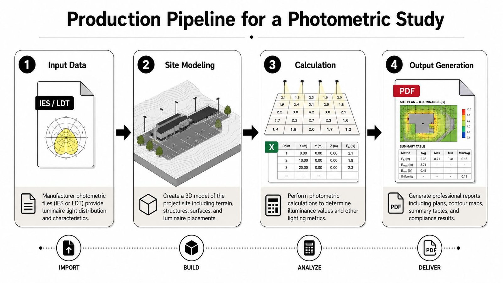
The tools and workflow
For site work, AGi32 is still the workhorse in many production shops. DIALux is common on projects that need a different regional workflow or an interior-heavy setup. ElumTools and Revit-integrated plugins matter when the photometric calculation has to stay tied to the BIM model instead of living in a separate file.
The modeler lays out the geometry, places the fixtures, defines the target plane, and runs a point-by-point grid. That output becomes the calculation summary, which is the document reviewers use to assess the numbers without reconstructing the entire model.
What a clean submission contains
A solid package usually includes:
- Photometric site plan, with fixtures, mounting heights, and calculation extents shown clearly
- Fixture schedule, with catalog numbers that match the study
- Cut sheets, so the reviewer can verify the photometric data
- Calculation summary, signed or otherwise packaged to show the results are intentional, not casual
When the package is organized like this, the reviewer can trace the logic from the source file to the drawing set without hunting through side comments.
Where the Photometric Plan Meets the Drawing Set
The photometric plan can't live in isolation. If the lighting plan, electrical plan, panel schedule, and site plan don't say the same thing, the reviewer starts looking for the mismatch instead of the compliance.
The reconciliation points that matter
The fixture count has to match across sheets. The wattage has to match the energy narrative. The mounting height has to match the design intent and the study assumptions. If any of those change, the numbers move, and the approval can unravel even if nobody touched the “photometric” sheet itself.
The biggest production failure is the quiet substitution. A GC swaps a fixture to save money, or an owner accepts a “like-for-like” replacement, and nobody reruns the study. That substitution can change distribution, delivered footcandles, and spill, which means the approved package is no longer the package being built.
Operational takeaway: any fixture substitution should travel with the revised cut sheet, the updated schedule, and a recalculated photometric summary. If one of those three is missing, the study is no longer the source of truth.
That's why the photometric plan belongs inside the drawing set, not floating beside it. The reviewer is checking consistency, not just light levels.
Why Photometric Submittals Get Rejected
Most rejection comments are less mysterious than they feel in the moment. They usually point to a missing assumption, a mismatch between sheets, or a study that was built for the wrong plane or ordinance.
The issues that come back most often
Missing property-line grid. If the calculation stops at the edge of the paved area, the reviewer can't tell whether light is spilling onto the neighbor. The fix is to extend the grid to the property boundary and show the boundary values plainly.
Wrong light loss factor. If the LLF is too optimistic, the report overstates delivered light. The fix is to use assumptions that match the fixture and maintenance condition, then regenerate the summary so the numbers aren't inflated.
Fixture substitutions without recalculation. This is common after value engineering. The fix is simple, but essential: rerun the study with the actual cut sheet and update the plan note package.
No egress path calculation. If the project includes life-safety lighting, the reviewer expects the path to be shown, not implied. The fix is to map the egress route and calculate the maintained values on the required plane.
Ignoring local dark-sky or BUG amendments. Base-code compliance doesn't save a design when the municipality has stronger language. The fix is to read the local amendment first, then tune the cutoff, aiming, and shielding accordingly.
A few quick answers come up at the permit desk all the time. A photometric calculation is the point-by-point lighting analysis that produces the plan and summary, usually delivered as a drawing package with supporting cut sheets. A photometric plan is required when zoning, egress, energy, or owner criteria call for it. Parking lots often need low, controlled maintained light levels rather than a single universal number, because the exact target depends on the jurisdiction and use. The most common tools are AGi32, DIALux, ElumTools, and Revit-based plugins. An IES file is the manufacturer's photometric data file, the raw distribution data the software reads to build the study.
For teams that already know the reviewer is waiting on a submittal, the fastest path is a complete permit set, not a partial one. The permit set coordination workflow pays off because the lighting study has to match the rest of the documents the first time it's reviewed.
If you need photometric studies and lighting plans as part of your MEP set, permit-ready, BIM Heroes can take the drawing-set coordination off your plate. Send over your scan data or project files, and visit BIM Heroes to request a free LOD recommendation and pricing within 24 hours.