


A framed house can look perfect at the end of a rough day, then fail the first time wind or seismic force pushes it sideways. That's where shear wall design matters. Gravity is the easy load, the part everyone sees. Lateral load is what racks the building, opens up corners, and exposes sloppy framing, weak connections, or a bad layout. This guide gives builders, GCs, and BIM teams a plain-English way to read the system, spot the weak points, and hand off a cleaner structural package for review.
What a Shear Wall Does in Plain Terms
A shear wall is the part of the structure that resists sideways force and sends it safely down to the foundation. In a house, that force comes from wind or seismic movement, not from the weight of the roof itself. The roof and floor act like horizontal collectors, the wall resists the push, and the foundation takes the final reaction.
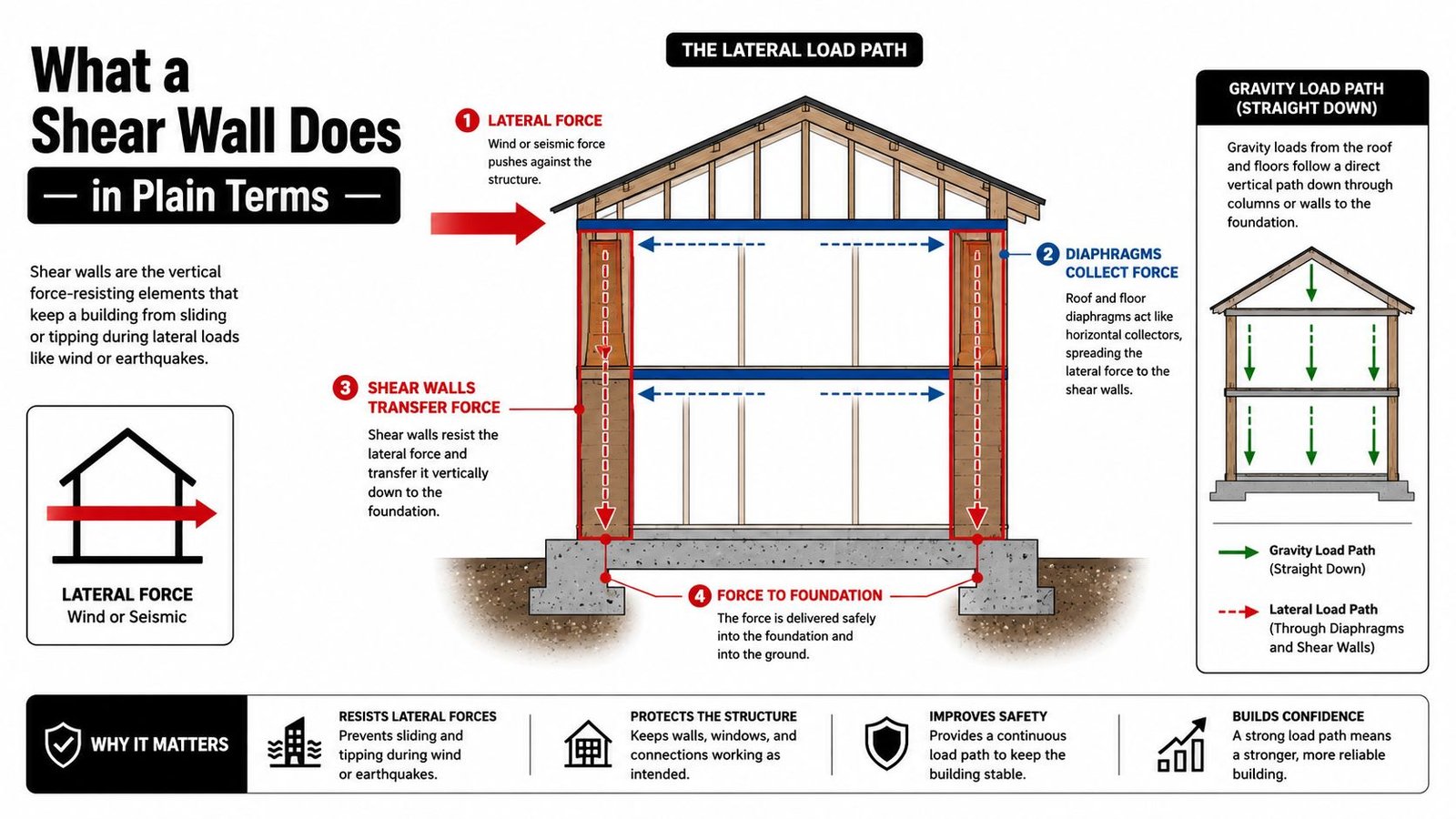
That load path is the whole story. If the diaphragm above can't collect the force, or the wall below can't transfer it, the building starts to rack instead of staying square. Builders usually see the symptoms first, like cracked finishes, tight doors going out of plumb, or a wall line that doesn't match the engineer's intent.
Practical rule: if you can't trace the force from the roof to the foundation on paper, it won't behave well on site.
The terms matter because they describe different jobs. Gravity framing carries weight straight down. Lateral framing handles the sideways push, and that's where shear walls do the heavy lifting.
Parts That Make Up a Shear Wall
On a framed house, a shear wall is usually the first place the lateral system gets tested, even though it looks ordinary from the outside. The assembly works as a unit, and if one part is missing or out of sync, the wall will not deliver the capacity the plan assumes.
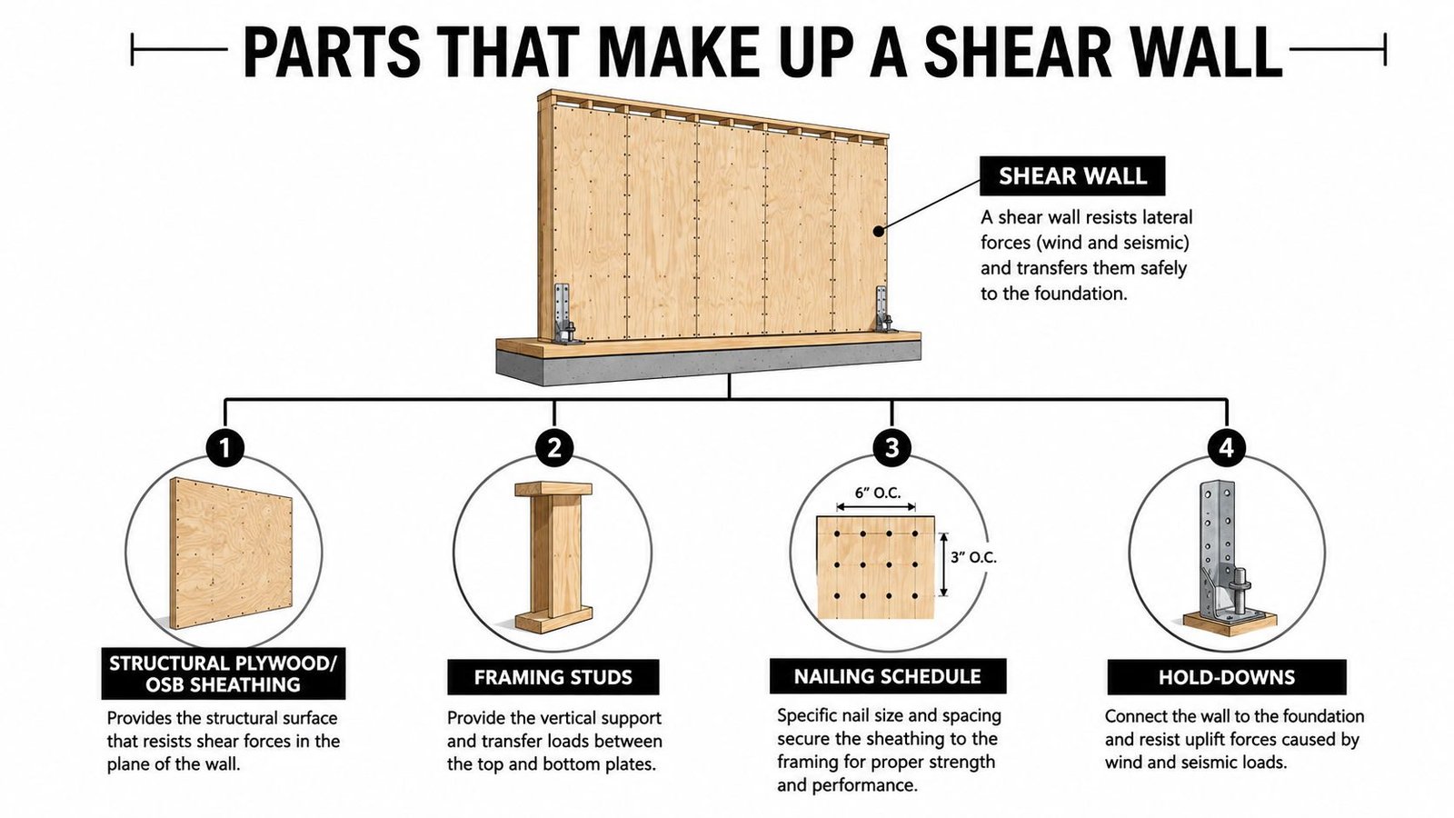
- Sheathing: structural plywood or OSB forms the face that resists in-plane shear. It has to match the wall design, and the panel choice matters on the plan and in the field. For a quick reference on different wall types in residential framing, this overview helps separate what belongs in the shear wall package from what does not.
- Nailing schedule: the fastener pattern connects the sheathing to the frame, and the spacing is just as important as the panel itself. A correct panel with the wrong nail pattern does not give you the same wall.
- Studs and chords: these members frame the wall and carry the boundary forces at the edges. They are the parts that keep the wall square while the load tries to rack it.
- Hold-downs and anchors: these resist overturning and uplift when lateral load tries to tip the wall over. On site, missed hardware or poor coordination usually gets exposed.
- Sill plate connection: this is the transfer point into the foundation. If the connection is weak, the wall does not hand off the force cleanly.
- Blocking: edge blocking helps force move cleanly through panel edges and openings. It also gives the nailing line something solid to land on where the layout gets interrupted.
The field mistake I see most often is treating the wall like a single material instead of a connected assembly. A good panel with bad anchors still fails. A good anchor with sloppy nailing does not save the wall either. The load path has to be complete from the sheathing to the foundation, and every connection in between has a job.
A shear wall is only as strong as its weakest connection, and that weak link is often the part nobody notices during the walkthrough.
In wood framing, production discipline shows up in layout, fastening, blocking, and anchor coordination. All of it has to match the structural intent, not just the rough opening count. If the plan shows a wall as part of the lateral system, the framing crew, inspector, and engineer all have to be looking at the same assembly, not three different versions of it.
Prescriptive Bracing Versus Engineered Shear Walls
On some jobs, the lateral plan stays clean because the house fits the prescriptive rules. On others, the first pass through the framing set shows too much glass, too many offsets, or too little wall length to stay inside that box. That split is where IRC wall bracing and engineered shear wall design part ways.
Residential projects usually fall into one of two lanes. The first is IRC wall bracing, where the code gives prescriptive braced wall panels and braced wall lines for conventional homes that stay inside the rule set. The second is engineered shear wall design, where a licensed structural engineer designs the lateral system under the IBC and related design standards for the project's actual loads and jurisdiction.
The difference shows up fast on the framing plan. A prescriptive layout depends on the plan matching the code path already laid out in the book, while an engineered layout gives the designer room to place shear walls where the structure needs them, even if the architecture is less cooperative. For a crew in the field, that changes how much freedom exists before the sheet gets handed to the inspector.
Large window walls, wide openings, tall two-story conditions, high wind or seismic exposure, and irregular geometry often push a project into engineered territory. The layout can also shift once the architect, builder, and engineer compare the wall lengths available against the loads the building has to carry. wood framing construction fundamentals matter here because the bracing discussion is only useful when the framing, sheathing, fastening, and connection details all line up on the same sheet.
The code history behind this discipline is not casual. Shear wall design has moved from early testing to formal rules over decades, including the 1967 Uniform Building Code's first allowable load tables for plywood shear walls and later updates for steel-framed and perforated wall terminology, as documented in the code history summary from McVicker. For current residential practice, the cleanest approach is to keep the scope clear and let the engineer own the final design.
For code context, the APA Engineered Wood Association keeps widely used bracing guidance for wood structural panels, which gives a practical reference point for coordination and review. APA braced wall guidance
Where Shear Walls Go on the Plan
Placement is where a lot of residential framing gets won or lost. Shear walls usually gather near corners, along exterior walls that run with the lateral load, and around openings that break up long stretches of wall. They also need balance across both axes so the house doesn't twist under load.
That twisting is called torsion, and it's one of the reasons wall quantity alone doesn't solve the problem. Research on irregular plans shows that wall location and orientation can materially change torsion, drift, and seismic response, so balanced layout matters as much as total wall length. In the field, that shows up when one side of the plan has plenty of wall and the other side has almost none.
Open floor plans make this harder. Big sliders, glass corners, and wide kitchen-living spans eat exactly the wall length the lateral design wants to use. The fix isn't usually “add more wall somewhere else,” because the engineer still has to manage the load path, the diaphragm, and the wall balance together.
Good bracing is rarely about squeezing in the most wall. It's about putting the wall where the force actually wants to go.
For builders, the right question is often, “Where can this wall help the structure without fighting the architecture?” That's why early coordination saves time. If the plan already shows a weak side or a long open span, the redesign conversation needs to happen before framing starts, not after inspection flags it.
How Shear Walls Show Up in the Documents
On a real structural set, shear walls are rarely left for guesswork. They show up in the framing plan, the wall schedule, and the details that control sheathing, fastening, and hold-down conditions. That is the page a framer has to read before the first panel goes up.
You'll usually see:
- Wall locations and extents, so the crew knows which segments belong to the lateral system.
- Sheathing and nailing notes, tied to wall type instead of field interpretation.
- Hold-down schedule and product callouts, so the overturning resistance matches the engineer's design.
- Opening and edge details, which show how load gets around windows, corners, and terminations.
- Foundation tie-in details, so the wall does not stop at the sill plate and leave the load path unfinished.
A clean framing plan helps the field crew build what the engineer intended, while the foundation connection has to be detailed well enough to carry the shear wall reaction into the concrete. If the roof structure is part of the lateral system, the lateral load path has to be coordinated with the roof layout too, which is why reading building construction drawings and truss roof design need to be aligned early.
Good structural documentation also protects the schedule. It cuts RFIs, reduces field interpretation, and gives the permit set a defensible answer when the reviewer asks where the lateral path starts and ends.
Common Shear Wall Mistakes in the Field
The failures repeat because the wall system gets treated like a set of isolated parts. On site, the trouble usually starts before the first sheet goes up.
A crew can frame a wall that looks square and still miss the load path. The wall then becomes a weak point the moment lateral force starts pushing on it.
- Wrong nailing pattern or spacing: the panel may look complete, but it will not perform the way the design expects.
- Missing or undersized hold-downs: the wall cannot resist overturning, so the ends give up the load path.
- Panels too narrow or too short: the segment may no longer qualify as intended, especially after openings take too much of the wall.
- Unbalanced placement: the building can twist, which increases torsion and drift.
- Sheathing gaps or missing edge blocking: the panel edge does not collect force cleanly.
- Broken connection to the foundation: the wall may be framed correctly and still fail where it transfers into concrete or framing below.
Those are field problems, but they usually begin in the drawings. Studies on irregular building plans show the layout itself can affect torsion, drift, and seismic response, so the issue is often not just a missed connector detail. It starts when the drawing set, framing layout, and foundation tie-in are not coordinated as one system, which is why the title on this topic matters less than the actual plan coordination behind it.
For a practical field check, I would read the wall line, verify the panel dimensions, confirm the fastener schedule, and trace the load path to the anchor points before anything gets covered. The same habit applies to interpreting building construction drawings, because that is where the shear wall intent either stays clear or gets lost. It is faster to catch the miss at that stage than to reopen finished work, and it usually costs less too.
Coordinated Documentation and a Clear Next Step
The part builders feel most is the gap between a good engineering concept and a usable framing package. That's where production teams earn their keep, by turning the engineer's lateral design into coordinated drawings that the field can build from, inspect against, and close out without constant redlines.
BIM Heroes supports that documentation layer with residential framing plans, foundation coordination, and structural production workflows that fit the engineer's stamped intent. For project teams that need cleaner handoff, that can mean structural documentation, framing sheets, and coordinated details that reduce RFIs before they start. For site teams, the value is simple, fewer surprises at the hold-down, fewer questions at the wall line, and a cleaner inspection path.
The line still stays where it should. Final shear wall design and verification belong to a licensed structural engineer for the project's loads and jurisdiction. Production support doesn't replace that. It helps the stamped design get built correctly.
If you're scoping a residential framing set or need help turning structural intent into coordinated documentation, send us your plans and we'll help you sort the buildable path from the redraws. If you want a practical second set of eyes on your lateral system, book a call with BIM Heroes and share the drawings you're working from.