Picture this: a large, prefabricated piping assembly arrives at your job site. A crane lifts it into place between two connection points, and it slots in perfectly. Every single bolt hole on every flange lines up. The crew torques the bolts, makes the connection, and moves on. No field cutting, no rework, no delay. The project keeps moving, on schedule and on budget.
Now, flip it. The same spool arrives, but it’s off by a half-inch because a dimension was wrong. A flange is oriented incorrectly, making the connection impossible. The entire installation grinds to a halt. Do they send it back? Can they even fix it in the field? Either way, the budget takes a hit, the schedule slips, and trust erodes.

The difference between these two outcomes often comes down to one of the most detail-sensitive documents in construction: the spool drawing. For anyone involved in piping construction—from MEP engineers to mechanical contractors—understanding what these documents are and what they must contain is essential for protecting margins and delivering predictable results. They are the blueprint for production maturity.
What Is a Spool Drawing?
A spool drawing is a fabrication document that breaks a complex piping system down into manageable, shippable segments—called "spools." These spools are prefabricated in a controlled shop environment and then assembled on-site.
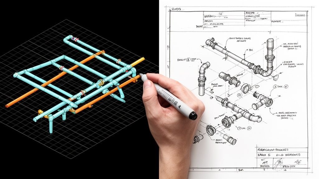
Think of it as the ultimate instruction manual for a fabricator. Each spool drawing represents one prefabricated piping assembly, showing all the information a fabricator needs to cut, weld, and assemble that specific piece. There’s no room for guesswork. This isn't a high-level overview; it's the A-to-Z recipe for a single, installable component.
It’s crucial to distinguish spool drawings from other piping documents:
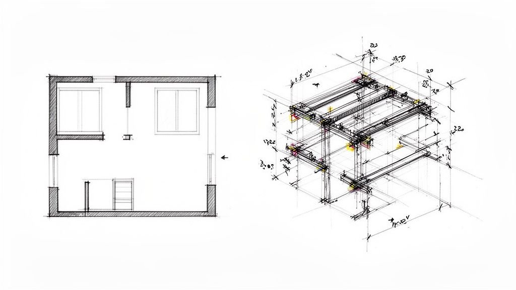
- Piping Layout Drawings show the entire system in the context of the building but lack fabrication-level detail. They are the master plan.
- Piping Isometric Drawings provide a 3D view of a piping run on a 2D page, clarifying geometry and routing but often omitting the granular details needed to build it.
- Spool Drawings are the final step, translating design intent into shop-ready instructions. They are the turn-by-turn directions for fabricating one segment.
This method started in oil and gas but has become a staple in any industry leveraging prefabrication for quality and efficiency. You’ll find piping spool drawings used across HVAC, plumbing, process piping, and industrial facilities. As MEP construction increasingly adopts off-site manufacturing, their importance only grows.
What a Spool Drawing Contains
A well-prepared spool drawing is packed with an immense amount of information. For a fabricator, this single sheet is the only source of truth. An error or omission isn’t a simple redline; it's a direct cause of rework, waste, and delay. To appreciate how much is at stake, let's break down the key elements.
Geometry and Dimensions
This is the foundation, defining the spool's physical shape and size. An error here is a guaranteed failure. A good drawing leaves no room for interpretation.
- Overall Spool Length and individual pipe segment lengths.
- All Bend Angles, Offsets, and elevation changes.
- Cut Lengths that account for fitting allowances and weld gaps.
- An Isometric View of the spool showing its spatial orientation.
Components and Materials
The drawing must provide a complete bill of materials (BOM) for that assembly. A mistake here can lead to compliance failures or even catastrophic system failure.
- Pipe Size, Schedule, and Material Specification for every single segment.
- All Fittings—elbows, tees, reducers—with their type and rating.
- Flanges with face type, pressure class, and bolt pattern clearly noted.
- Valves, Strainers, and any inline instruments included in the spool.
- Gaskets and Fastener specifications where relevant.
Fabrication Notes
This layer provides the "how-to" for the fabrication process itself, ensuring the spool is built to project standards.
- Weld Symbols and references to the governing weld procedure.
- Surface Treatment, coating, or insulation requirements.
- Pressure Testing Requirements for the completed spool.
- A Unique Spool Tag or identification number for tracking.
Reference Information
These details connect the spool back to the larger project, providing critical context for QA and installation.
- Line Number and the system it belongs to.
- Reference to the Parent Isometric or piping layout drawing.
- Revision History and approval status.
This level of detail is a lesson learned in the field: the more clarity you provide the shop, the fewer problems you'll have on-site. Every dimension and callout is a decision checkpoint that prevents RFIs and protects the schedule.
How Spool Drawings Fit Into the Construction Workflow
Spool drawings sit at the critical intersection of design and fabrication. They are the deliverable where engineering intent becomes physical reality. Understanding their journey highlights the importance of getting each step right.
- Design & Coordination: The process starts with the design team producing piping layout and isometric drawings within a coordinated 3D environment. This is the CAD-to-BIM evolution in action, where clash detection ensures the routing is buildable before any drawings are cut.
- Defining Spool Breaks: A detailer or project engineer uses the BIM model or isometrics to decide where each prefabricated segment begins and ends. This is a crucial decision checkpoint, balancing shipping constraints, site access, and shop capabilities.
- Drawing Production: Spool drawings are then produced, either manually or extracted directly from the BIM model. This is a core function of a scalable delivery pod focused on production maturity.
- Review & Approval: Drawings undergo a rigorous QA process before being approved and issued to the fabrication shop.
- Fabrication: The fabricator uses the drawings to cut, weld, and assemble each spool, tagging it with its unique spool number.
- Shipping & Installation: Completed spools are shipped to the site and installed in sequence by the field crew.
- As-Builting: Any field changes or deviations are marked up on the drawings to create a final, accurate record for facility management.
Errors at the spool drawing stage don't get caught in an office. They get caught when a crane is holding a multi-thousand-dollar pipe assembly in the air and it doesn't fit. This workflow emphasizes the need for template discipline and robust QA processes to ensure operational consistency.
Why Spool Drawing Accuracy Matters So Much
The promise of prefabrication—cost savings, schedule compression, and superior quality—hinges entirely on the accuracy of the fabrication documents. Spool drawings are the linchpin. When they are correct, projects gain predictability. When they are wrong, the financial and logistical consequences are severe.
- Margin Protection: A single incorrect dimension can force a spool to be cut and rewelded in the field, or scrapped entirely. This rework obliterates any cost savings and directly erodes project margins.
- Preventing Costly Rework: Flange orientation errors are among the most common and costly mistakes. A flange rotated by just a few degrees means the bolt pattern won’t align, stopping installation cold. The only fix is an expensive field repair.
- Ensuring Compliance: Material specification errors can cause compliance failures, especially in pressure-rated or code-governed systems like those in healthcare or industrial facilities. This can lead to failed inspections and mandatory replacement.
- Maintaining Schedule: On large projects with hundreds of spools, even a small error rate compounds quickly. A 5% rework rate across 200 spools means 10 separate fire drills, each one a threat to the project schedule.
- Building Trust: Beyond the rework, inaccurate spool drawings erode trust between the design team, fabricator, and contractor. This friction creates RFIs, slows down decision-making, and poisons the collaborative environment needed for success.
Treating these documents with professional rigor isn't about being academic; it's about operational excellence. Accuracy here is a direct lever for ensuring predictability and protecting profitability.
The Connection Between BIM and Spool Drawing Quality
Traditionally, spool drawings were produced manually from 2D isometrics. A detailer would interpret the drawings, calculate cut lengths, and redraw everything—a process prone to transcription errors and dimensional inaccuracies.
Building Information Modeling (BIM) transforms this workflow. When piping systems are modeled accurately, BIM spool drawing production moves from manual interpretation to model-driven extraction.
- Data-Driven Accuracy: Instead of being manually entered, dimensions, components, and material specifications are pulled directly from the model data. This dramatically reduces the risk of human error. The drawing reflects the model, not an interpreter's reading of it.
- Upstream Clash Detection: BIM workflows resolve coordination issues before fabrication begins. By the time spool drawings are generated, the routing is already confirmed to be clash-free, preventing fabricators from discovering conflicts in the field.
- Efficient Revision Management: When a design changes, the BIM model is updated, and the spool drawings can be regenerated. This is far more reliable than manually redlining dozens of sheets and hoping nothing gets missed.

The quality of the BIM model directly determines the quality of the spool drawings it produces. This is why modeling discipline and a clear understanding of the required Level of Detail in BIM during the design and coordination phases are so critical. A well-built model is the foundation for reliable delivery.
Industries and Project Types Where Spool Drawings Are Most Critical
While valuable everywhere, the rigor of spool drawing production is non-negotiable in certain environments where complexity, compliance, and speed are paramount.
- Oil and Gas: The original home of spooling, where pressure ratings, material traceability, and safety are absolute.
- Industrial and Process Facilities: Chemical plants, food processing, and pharmaceutical facilities with dense, highly engineered piping systems.
- Data Centers: Projects with complex chilled water and refrigerant piping where prefabrication is essential for meeting aggressive schedules.
- Commercial MEP: Increasingly relevant as mechanical contractors adopt prefabrication for HVAC and plumbing systems to improve site productivity and safety.
- Healthcare and Laboratory Facilities: Where system reliability, cleanliness, and code compliance make field fabrication undesirable and high-risk.
In each of these sectors, MEP prefabrication drawings are not just a best practice; they are a core component of a mature and scalable delivery strategy.
How BIM Heroes Supports Spool Drawing Production
BIM Heroes operates as an embedded production partner for MEP engineers and mechanical contractors who need reliable fabrication documentation. We don't just sell hours; we deliver clarity, systems, and dependable outcomes.
Our team produces fabrication-level piping documentation as part of our MEP engineering services.
- We work from coordinated BIM models to extract accurate spool drawings with correct dimensions, component callouts, and material specifications.
- We are deeply familiar with US piping standards, ASME specifications, and the level of detail fabricators expect.
- We operate with template discipline and robust QA processes to ensure every drawing is shop-ready.
- We stay engaged through revisions and coordination, ensuring the documentation stays aligned with project realities.
Our goal is to help you achieve operational consistency and margin protection by providing the reliable documentation you need without expanding your in-house team.
From Documentation to Predictable Outcomes
We started with two scenarios: the spool that fits perfectly and the one that causes a costly delay. The difference is not luck. It is the result of a disciplined production system that treats spool drawings as a critical link in the fabrication chain, not a back-office task.
As the industry moves further toward off-site fabrication, the ability to produce accurate, complete spool drawings becomes a genuine project differentiator. Firms and production teams that treat this deliverable with the rigor it deserves will see fewer field problems, stronger fabricator relationships, and more predictable project outcomes. They are the ones who understand that clarity in the office prevents chaos on site.
Need accurate spool drawings for your next piping or MEP project? Let's talk about how BIM Heroes can support your fabrication documentation workflow.