Meta description: Coordinated ceiling plenum design fails when teams trust plan views and defer above-ceiling decisions too long. This guide shows how to manage routing hierarchy, section checks, BIM validation, and plenum code constraints before field conflicts turn into RFIs.
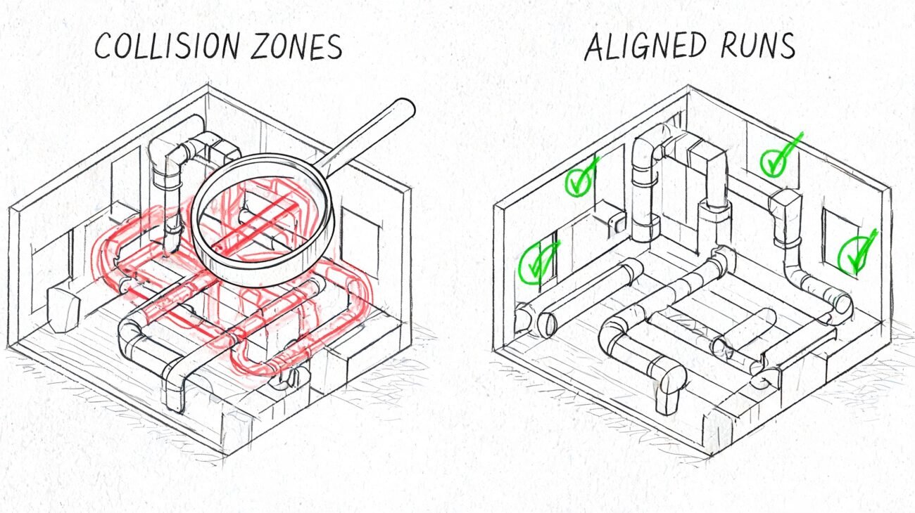
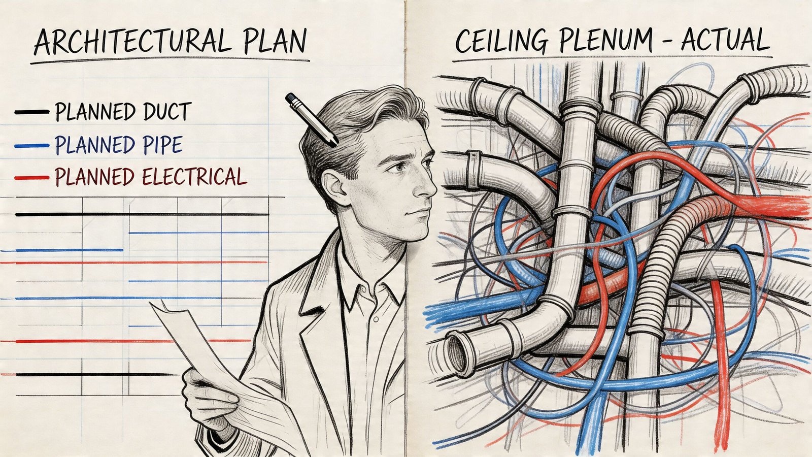
A project can look coordinated all the way through DD in plan. Then someone cuts a corridor section and the whole story changes. The supply duct clips a beam. The sprinkler main sits where the light fixture needs depth. The cable tray steals the only clean crossing zone. The VAV box fits on paper but not with access.
That’s why coordinated ceiling plenum design deserves its own process, not a late clash report. In most commercial work, the plenum ceiling is where structure, HVAC, fire protection, electrical, lighting, and architecture all compete inside a narrow vertical zone. If that zone isn’t planned deliberately, the job drifts into RFIs, field improvisation, and expensive redraws.
The firms that handle this well don’t rely on a final Navisworks run to save them. They lock routing priorities early, test the section before the reflected ceiling plan gets too far, and carry those rules through LOD progression, QA, and permit documentation.
The Hidden Chaos Above the Ceiling
The failure usually starts with a false sense of confidence.
An architect sees a clean reflected ceiling plan. The mechanical engineer sees a workable duct layout. Electrical has trays and branch routing in place. Fire protection is “to be coordinated.” Nothing looks alarming until the model is reviewed in section, especially in the main corridor where every trade wants the same airspace.
That’s the moment the plenum ceiling stops being an abstract coordination topic and becomes a production problem. If you’ve reviewed enough projects, you can almost predict where it breaks first. Corridors. Lobby transitions. Shaft approaches. Areas with beam drops. Anywhere ceiling height is architecturally sensitive and MEP density is high.
A lot of the recurring issues show up in the same family as other common coordination issues in multi-discipline projects. The difference above the ceiling is that vertical space is finite and unforgiving. A line can shift in plan. A duct with fittings, insulation, and hangers can’t magically disappear in section.
Why the plenum ceiling becomes the battleground
Modern commercial interiors make this harder, not easier. Open plenum ceilings have gained significant popularity since the early 2010s in U.S. commercial architecture for exposed-ceiling aesthetics and cost savings, but Johns Manville notes that removing traditional acoustic ceilings also removes an important sound barrier. Traditional suspended acoustic ceilings typically provide 20 to 25 CAC points, while open-plenum conditions can lose performance further because penetrations from lights, diffusers, and speakers reduce that barrier by up to 10 points. Johns Manville also notes that ceiling tiles and finishes can account for 10 to 15% of interior fit-out budgets in mid-sized projects, which is one reason teams chase exposed solutions in the first place (Johns Manville on open plenum adoption and trade-offs).
That trade-off matters in coordination. Exposed ceilings may reduce one layer of finish work, but they increase the visibility of every misaligned duct, offset conduit run, and poorly planned crossing.
Practical rule: If a corridor only works in plan, it isn’t coordinated yet.
Reactive clash detection doesn’t fix bad decisions
A late clash report can identify collisions. It can’t fix bad priorities, unrealistic ceiling heights, or missing access zones. By the time the model is full of unresolved duct-versus-beam and tray-versus-sprinkler conflicts, the project team is negotiating from a bad starting point.
That’s why the reliable approach is front-loaded. Freeze the decision logic early. Build around a routing hierarchy. Validate with sections, not just plans. Then use BIM to enforce the system, not to rescue it.
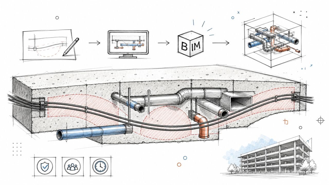
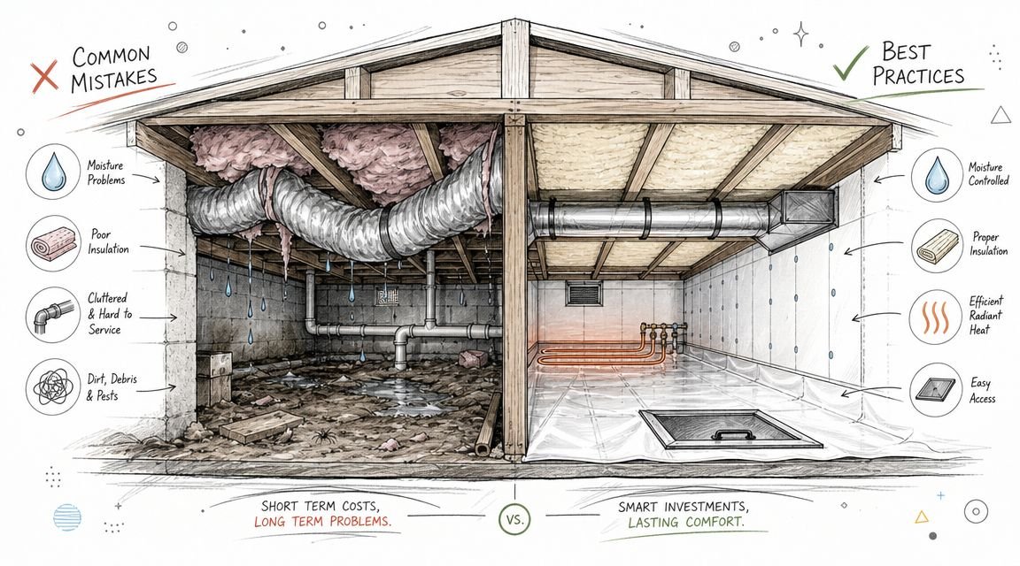
Anatomy of a Congested Plenum Space
The plenum space in commercial buildings isn’t empty overhead volume. It’s a stacked service zone with competing geometries, code constraints, and maintenance requirements. If the team doesn’t inventory that stack early, the model will lie by omission.
What is actually above the finished ceiling
Start with structure. Beams, joists, slab depressions, transfer framing, and brace locations define the hard top boundary. Those elements don’t move just because a corridor wants a cleaner ceiling line.
Then add the systems that consume the most depth:
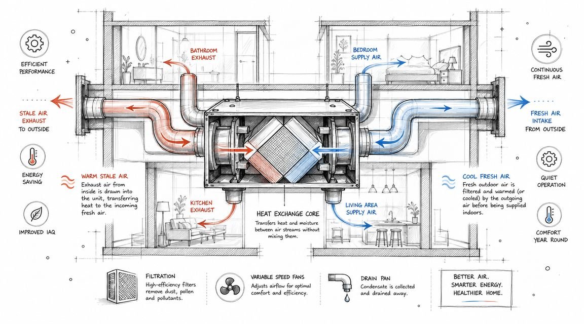
- Primary HVAC ductwork: Main supply and return trunks are usually the dominant geometry in corridor routing. Their fittings, transitions, and branch takeoffs create the first real vertical occupation problem.
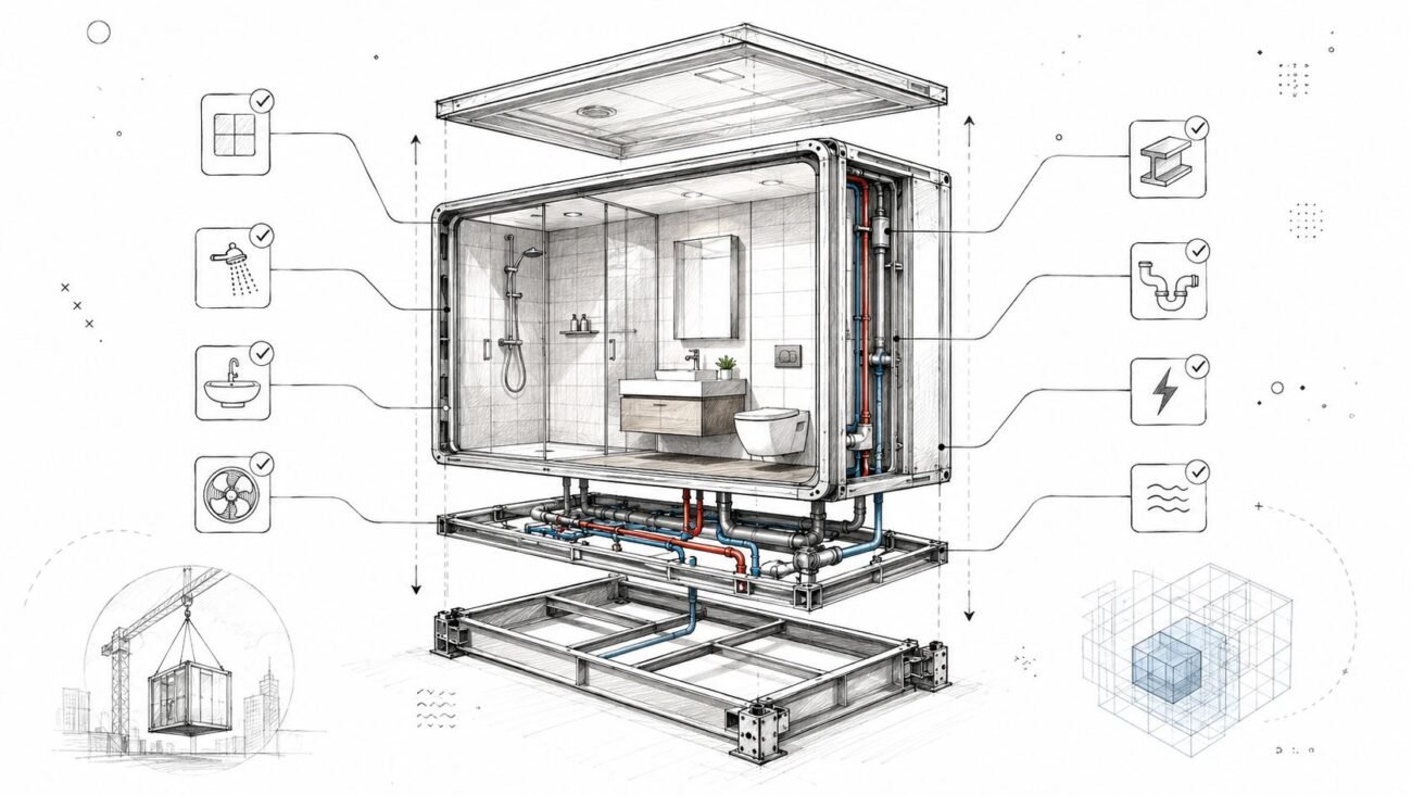
- Terminal equipment: VAV boxes, fan coil units, and similar equipment often fit dimensionally but fail once access space is considered.
- Fire protection piping: Sprinkler mains and branches don’t just need a path. They need location discipline relative to ducts, structure, and ceiling devices.
- Hydronic piping: Chilled water and hot water lines become much bigger in practice once insulation is included.
- Electrical trays and conduit: Trays are deceptively disruptive because they’re wide and want straight longitudinal routes. Conduit is flexible, but in bulk it becomes the fill material that destroys leftover coordination space.
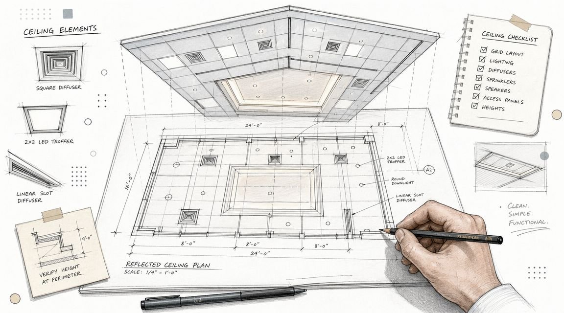
- Lighting and ceiling devices: Fixtures, speakers, diffusers, sensors, access panels, and life-safety devices all consume the lower edge of the plenum.
A lot of teams model these as separate discipline scopes. That’s exactly why the plenum ceiling becomes congested late. No one owns the full stack until the federated review.
The code layer makes it tighter
The plenum also has material restrictions that teams often underestimate. Materials in plenum ceilings above suspended ceilings must meet 25/50 flame spread and smoke developed ratings under ASTM E84, as required by model codes such as IBC and IMC for commercial buildings (Corzan on plenum ratings and ASTM E84 25/50 requirements).
That affects more than specification language. It changes what can physically be routed through the space, what fixture housings need to do, and how late substitutions can trigger redesign.
If your process doesn’t connect code requirements to model content, the problem shows up in procurement or inspection instead of design. In these instances, teams that produce disciplined HVAC duct layout drawings usually have an advantage. They tend to think in section, not just in linework.
Why dimensions are only half the story
Even when every modeled object fits, the plenum can still fail operationally.
Use this quick checklist during coordination review:
| System or constraint | What teams miss most often |
|---|---|
| HVAC mains | Fittings, flanges, and turning radius |
| VAV and terminal units | Service clearance and actuator access |
| Piping | Insulation thickness instead of bare pipe diameter |
| Cable tray | Crossing points that block future routes |
| Sprinklers | Positioning conflicts with duct bottoms and ceiling devices |
| Lighting | Fixture depth inside already-tight ceiling zones |
| Structure | Beam drops that vary by bay and ruin a repeated corridor rule |
A plenum ceiling rarely fails because one system is oversized. It fails because several reasonable assumptions occupy the same section at once.
That’s why plenum space planning commercial buildings can’t be delegated to “coordination later.” The dimensional puzzle is real, but the process discipline is what keeps it solvable.
Why Good Plans Go Bad The Three Root Causes of Plenum Conflicts
Most plenum failures aren’t design talent problems. They’re process failures that keep repeating under different project names.
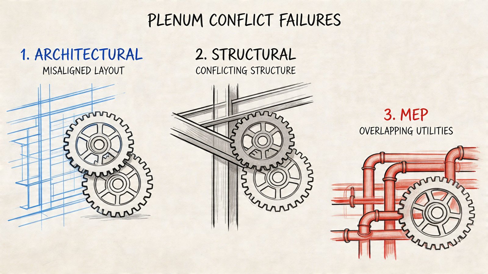
Ceiling height gets fixed before the section gets tested
The first mistake happens early. The architectural team sets a finished ceiling elevation based on layout, proportions, and program needs. That’s normal. The problem starts when nobody pressure-tests whether the remaining plenum can carry the systems it’s expected to carry.
Once that ceiling line is embedded in interiors, elevations, envelope coordination, and code clearances, moving it becomes painful. Every late ceiling adjustment ripples into doors, glazing heads, millwork alignment, and accessibility checks.
Trades design in parallel without a routing hierarchy
The second failure is ownership confusion. Mechanical draws ducts as if it has first priority. Electrical routes trays as if corridor centerline is available. Fire protection comes in later and assumes enough room remains. Plumbing needs slope somewhere. Then the team federates the model and acts surprised.
Without a routing hierarchy, coordination meetings become trade-by-trade bargaining sessions. Whoever modeled first acts entrenched. Whoever modeled last gets forced into awkward offsets and fragmented routes. That isn’t coordination. It’s arbitration.
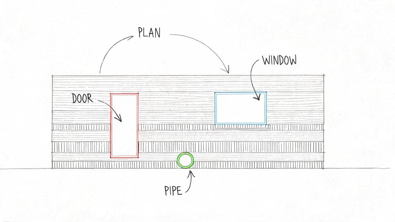
Teams trust plan views too long
The third failure is visual. Plan views hide vertical conflicts extremely well. A duct and beam can appear unrelated in plan while occupying the same elevation range in reality. The same goes for tray crossings, branch takeoffs, and equipment access.
This is why late-stage surprise sections are so destructive. They expose issues that were always present but never made visible in the working process.
“Looks fine in plan” is one of the most expensive phrases in coordination.
There’s also a budget blind spot tied to compliance. The financial trade-offs around plenum-rated materials and retrofit strategies are often not quantified early, which leaves interior and renovation teams without a clean basis for advising clients when hidden compliance scope appears later (ACHR News on the overlooked cost-benefit gap in plenum compliance).
The three causes show up fast in practice
You can usually identify the underlying cause from the kind of RFI that lands first:
- Ceiling revision RFIs usually trace back to early elevation decisions made without plenum analysis.
- Trade conflict RFIs usually point to missing routing priority.
- Field fit RFIs usually come from plan-only validation and weak section review.
Once those patterns become visible, the fix is straightforward. The team needs one routing rulebook, one dimensional checkpoint, and one repeatable section-based review cycle.
The Routing Hierarchy Who Moves and Who Stays
If you want to reduce above-ceiling noise in coordination meetings, decide the routing hierarchy before detailed modeling starts. Put it in the BIM Execution Plan. Tie it to model review. Use it in every clash triage meeting.
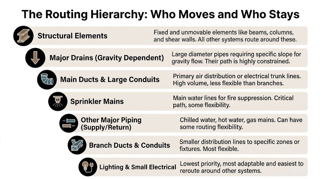
The hierarchy works because it reflects effort, geometry, and constraint. Some systems are effectively fixed. Some can move, but at disproportionate cost. Others should be routed last because they’re adaptable.
Start with systems that define the envelope
At the top sit structural elements. Beams, columns, slab edges, brace zones, shear walls, and transfer framing establish the spatial limits of the plenum ceiling. They are the reference frame for every other trade.
Gravity-dependent drainage belongs near the top as well. Sloped sanitary and storm piping can’t be treated like pressure systems. Their path is constrained by invert elevations and slope continuity, so they need early resolution, especially near restrooms, shafts, and horizontal transfer zones.
Major air and water routes come next
Primary HVAC mains usually deserve the next tier because they are large, branch-intensive, and expensive to reroute once a corridor layout is built around them. Main ducts should take the cleanest routes available, especially where future branch logic depends on straight distribution.
Hydronic mains also belong high in the stack. Once insulation is included, their size and hanger requirements make them less flexible than teams assume. If they need to transition around structure, that move should be designed, not improvised after clashes are found.
Flexible systems should fill remaining zones
Sprinkler mains and branch lines often have some routing flexibility, but they still need disciplined placement. They cannot inherit leftover space after mechanical and electrical have filled the plenum.
Cable trays can often accept elevation changes or be assigned to corridor edges rather than centerline. Conduit and low-voltage systems are usually the most adaptable, which is exactly why they should not claim premium routing space too early.
MEP trade routing hierarchy
| Priority Tier | System | Reasoning |
|---|---|---|
| Fixed | Structural beams, columns, slabs | Defines the hard boundary of the plenum |
| Fixed to high | Gravity drainage piping | Requires slope and early resolution |
| High | Primary HVAC duct mains | Large geometry, fittings, and branch logic make rerouting costly |
| High | Chilled and hot water mains | Insulated size and support needs reduce flexibility |
| Medium | Sprinkler mains and branches | Can adjust, but only within fire protection constraints |
| Medium | Electrical cable trays | Wide and space-hungry, but usually more flexible than main ducts |
| Low | Conduit runs | Small individually, manageable when zoned properly |
| Lowest | Low-voltage and fire alarm branch routing | Best used to fill controlled leftover space |
This hierarchy also needs to respect the code environment. NEC Article 300.22 requires plenum-rated cables in air-handling spaces, and plenum-rated CMP cable can reduce smoke by 70 to 80% compared with traditional PVC. The same source notes that 60 to 70% of commercial suspended ceiling installations use the plenum for air return, which is one reason cable selection matters so much in above-ceiling coordination (Wikipedia summary of plenum space code requirements and CMP cable performance).
What works in meetings and what doesn’t
What works is simple:
- Document the hierarchy early: Put it in the BEP and in coordination kickoff notes.
- Assign corridor zones: Reserve sides or bands for tray, controls, or branch systems.
- Use one decision-maker for conflict triage: Usually the BIM coordinator or lead engineer, not open-floor negotiation.
What doesn’t work:
- “We’ll sort it out in clash detection.”
- Letting every trade assume equal corridor priority.
- Allowing unresolved penetrations and hoping structure approves later.
Coordination standard: If a team can’t answer who moves first, the model isn’t ready for meaningful clash review.
The Proactive Plenum Depth Calculation
The best time to solve a plenum ceiling problem is before anyone gets attached to the ceiling height.
This check should happen during schematic design or very early DD. It doesn’t need fabrication detail. It needs honest dimensional stacking. The point is to test whether the architectural ceiling can coexist with structure and major MEP routing before the rest of the model hardens around it.
Run the stack from top to bottom
Start with the floor-to-floor or slab-to-slab condition established by the structural concept. Then subtract what is already spoken for.
Use this order:
- Structural depth first. Beam and joist depth can consume a large part of the available zone before any trade enters the conversation.
- Primary duct depth next. Don’t use a symbolic duct. Use the actual corridor main size expected for the distribution strategy, including practical assembly depth.
- Sprinkler and crossing allowances. The fire protection designer needs workable relationship to duct bottoms and ceiling devices.
- Ceiling assembly depth. Grid, backing, fixture bodies, and specialty ceiling conditions all matter.
- Serviceability. A box that physically fits but can’t be accessed shouldn’t count as fitting.
Treat the result as a checkpoint, not a suggestion
If the remaining plenum is too tight, the team has only a few honest options. Revise the ceiling height. Rework the structural framing strategy. Change the HVAC distribution concept. Rezone corridors. None of those moves gets easier if delayed.
The common failure is not doing the math. The common second failure is doing it once, then letting scope creep consume the margin. A lobby ceiling feature, a larger return path, a tray added for IT, or a shifted beam line can erase the available slack fast.
Why this protects design intent
Architects usually don’t lose ceiling height because someone “moved late.” They lose it because the project promised an elevation before checking the above-ceiling stack.
A disciplined plenum depth calculation protects the architecture by challenging assumptions early enough to still have options. It also gives PMs a cleaner basis for decision checkpoints. If the plenum doesn’t work in section during SD, it won’t heal itself by permit.
Check the plenum before you sell the ceiling.
This is also where open plenum ceilings need sober review. Exposed systems can help recover visual height in some spaces, but they also increase coordination demands, acoustic exposure, and finish expectations. If the team chooses that route, the decision should be intentional and modeled accordingly.
Section-Driven Validation A BIM-Powered Workflow
Good coordinated ceiling plenum design is built in section and enforced in BIM.
Plan views still matter. They’re useful for organization, branch logic, and routing intent. But they are not the primary validation tool in a congested plenum ceiling. Section cuts are where the truth shows up.
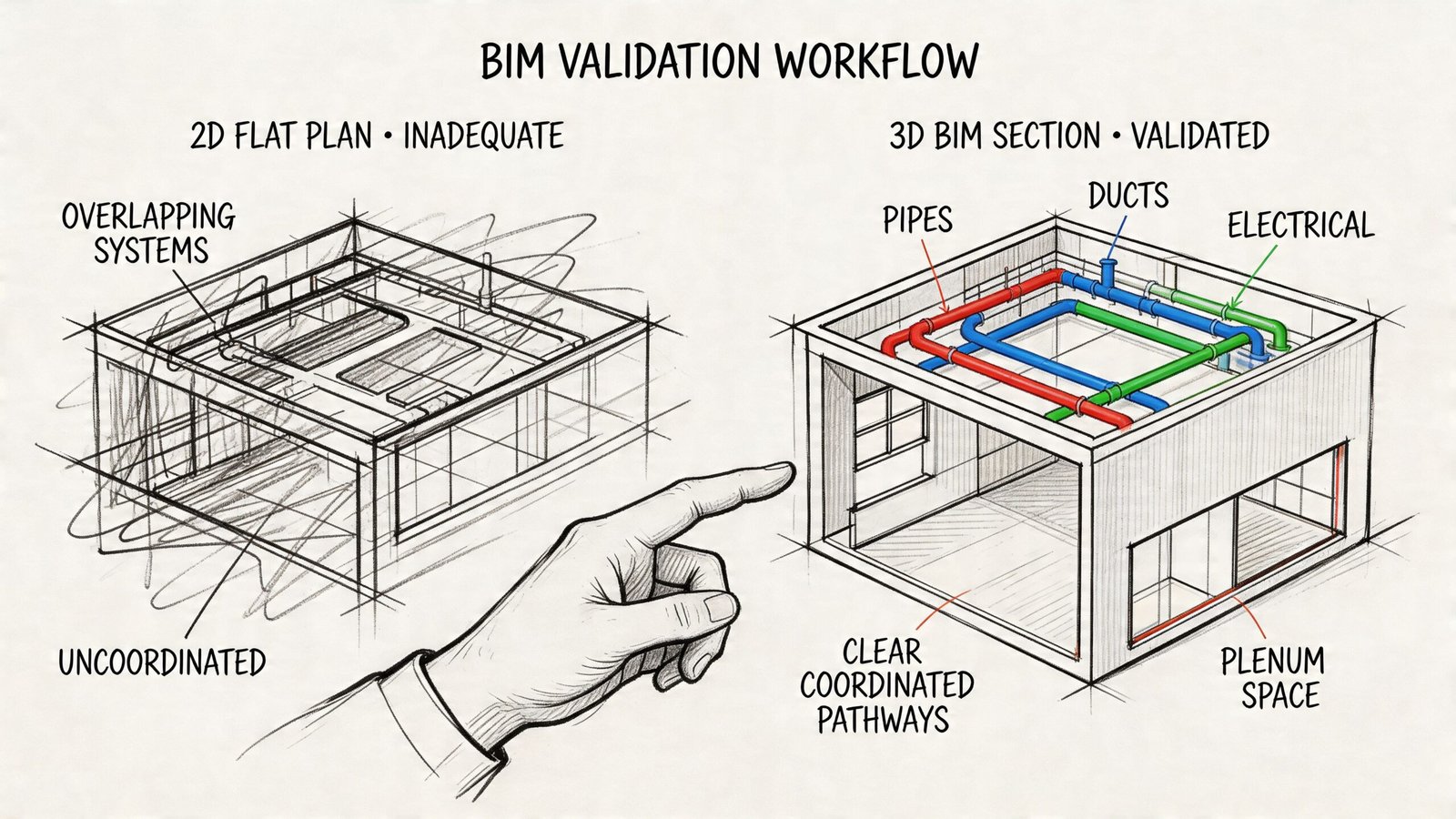
Use federated sections, not isolated discipline views
In Revit, the most productive review setup is a federated model with linked architectural, structural, mechanical, plumbing, fire protection, and electrical content visible together. That lets the team cut coordinated sections through every dense corridor and transition zone instead of reviewing trade models one at a time.
That workflow becomes stronger when teams build it into their production cadence. Regular section reviews at defined milestones catch the routing conflict before it turns into a field compromise. Firms that need a cleaner production baseline often improve this process by standardizing their MEP workflows in Revit around shared view templates, clash sets, and coordination checklists.
Reserve space early with LOD discipline
A mature ceiling plenum BIM workflow starts before every fitting is modeled.
At LOD 200, reserve placeholder volumes for major duct trunks, key piping corridors, and equipment zones. This is the right stage to test whether the architecture can afford the mechanical idea, not the stage to model every branch.
At LOD 350, move into true coordination geometry. That means actual duct sizes, insulation thickness, support implications, and realistic equipment footprints. If the model is supposed to support above-ceiling coordination drawings, symbolic simplifications won’t hold.
Clash detection should be tiered
One of the fastest ways to bury a project team is to run every clash against everything else and dump the report into a meeting. You’ll get noise, not decisions.
A better sequence looks like this:
- Tier one: Structure versus major MEP mains
- Tier two: Mains versus mains across trades
- Tier three: Branches, devices, and access clearances
- Tier four: Finish interface, ceiling devices, and special conditions
That sequence mirrors the routing hierarchy. It also keeps the team focused on the conflicts that change corridor strategy.
BIM still needs a process wrapper
The software doesn’t solve plenum coordination on its own. One persistent gap in the industry is that while plenum code requirements are clear, there’s no standardized guidance for embedding those requirements into BIM workflows. Firms often lack consistent methods for flagging plenum zones in models or validating material restrictions early enough to avoid field corrections (continuing education reference on the BIM coordination gap for plenum compliance).
That lines up with what many teams see in practice. The model may be geometrically coordinated but still under-defined from a compliance standpoint if plenum zones aren’t explicitly tagged and reviewed.
The best ceiling plenum clash detection in Revit is useless if the model never reserved space for the right systems in the first place.
For external reference on fabrication and duct practice, teams should still align routing assumptions with SMACNA standards. The standard doesn’t replace coordination, but it keeps routing decisions tied to constructible duct behavior instead of idealized geometry.
Field Problems That Start in the Model
The field usually pays for small digital shortcuts.
Experienced PMs know this pattern. The issue that triggers a site walk often began as a modeling omission that looked harmless at the time.
Five mistakes that age badly
- VAV boxes placed without access logic: The model shows the unit fitting between structure and ceiling, but no one checked service approach below or adjacent tile removal. The install technically works. Maintenance doesn’t.
- Sprinkler branch lines tucked into leftover voids: The branch route clears in model space, then inspection catches a bad relationship to the final duct bottom or ceiling condition.
- Cable trays crossing corridors in the wrong spot: A tray gets the shortest route to a panel, and that crossing becomes a permanent obstruction that forces every later duct transition into offsets.
- Assumed structural penetrations: Mechanical or plumbing route through beam zones before structural approval. Then the shop drawing review closes the opening, and the trade has to redesign around a condition it thought was already solved.
- Bare pipe coordination: Hydronic or condensate lines are modeled without full insulation build-up. The coordination review passes. The constructed section fails once insulation is added.
High-risk conditions need tighter modeling
Some projects also include specialized plenum ceiling assemblies in critical spaces. Durasteel plenum ceiling systems, for example, can achieve up to 4 hours of fire resistance, support loads up to 15kN/m², and remain less than 90mm deep. That performance is valuable in high-risk environments, but it also demands precise BIM coordination with the surrounding MEP and support conditions (Durasteel plenum ceiling system performance data).
That kind of assembly doesn’t tolerate vague coordination. Neither do service corridors with dense life-safety routing, smoke extraction requirements, or constrained retrofit work.
What the field teams usually need from design
Field crews don’t need a beautiful federation screenshot. They need clarity.
That usually means:
- Above-ceiling coordination drawings with real section cuts
- Approved routing zones
- Resolved beam penetration decisions
- Clear access requirements for equipment
- No hidden assumptions about insulation, supports, or fixture depth
If those items are weak, the field invents the answer. Sometimes that works. Usually it becomes an RFI, a rework cycle, or a compromised installation.
From Reactive Fixes to Proactive Control
A plenum ceiling doesn’t become coordinated because the software is powerful. It becomes coordinated because the team follows a disciplined sequence.
Set the routing hierarchy early. Test the plenum depth before locking ceiling heights. Review the corridor in section, not just in plan. Run clash detection in tiers that match real construction priorities. Carry those rules from LOD 200 placeholders into LOD 350 coordination detail. That’s what turns ceiling plenum MEP coordination from reactive cleanup into controlled production.
The payoff is predictability. Fewer late RFIs. Fewer “minor” ceiling revisions that aren’t minor at all. Fewer coordination meetings spent renegotiating space that should have been assigned from the start. For small-to-mid-sized AEC firms, that’s margin protection as much as it is technical quality.
Firms that do this consistently don’t look lucky. They look organized. Their models communicate intent. Their above-ceiling coordination drawings are reviewable. Their permit set stands up better because the hard decisions were made before CDs became a deadline problem.
If your team wants a more repeatable way to handle coordinated ceiling plenum design, BIM Heroes can help with project assessments, BIM workflow frameworks, and multi-discipline production support that brings structure to above-ceiling coordination before it turns into field rework.