Meta description: Fire alarm system design fails at permit when code intent, ceiling coordination, and documentation production are handled as separate tasks. Learn how BIM-based workflows, QA checkpoints, and disciplined Revit production help teams deliver permit-ready fire alarm drawings.
A permit set goes out on Friday. By Tuesday, comments are back. The reviewer wants pull stations relocated, detector coverage clarified, candela and mounting information coordinated with the reflected ceiling plan, and interface notes added for connected systems. None of those markups looks catastrophic on its own. Together, they send the sheet set back through architecture, electrical, interiors, mechanical, and BIM production.
That pattern is common because fire alarm drawings are often produced too late and checked too narrowly. The issue is rarely symbol placement alone. It is production maturity. Teams need a repeatable process that ties code decisions, model coordination, ceiling development, and sheet output into one controlled workflow. Firms that already treat other permit packages this way usually see the difference quickly in their permit drawing production process.
The cost shows up in rework first. The National Institute of Building Sciences reports that inadequate interoperability in the U.S. capital facilities industry creates billions in avoidable cost across design, construction, and operations, as outlined in its interoperability cost analysis. The lesson for fire alarm documentation is practical. When model data, consultant inputs, and sheet annotations do not stay aligned, permit comments become redesign hours, and redesign hours cut directly into fee and schedule.
For architects and MEP engineers who do not design fire protection every day, the path to reliable fire alarm documentation is not complicated, but it does require discipline. Build the layout from code-backed decisions. Coordinate devices against actual ceilings and trade conditions. Use BIM to check conflicts before plotting sheets. Then issue a set that reads clearly to reviewers, contractors, and the field team on the first pass.
Introduction Why Fire Alarm Drawings Cause Permit Headaches
Why these drawings look easier than they are
Fire alarm plans often arrive late in the document set and look deceptively clean. A few detector symbols, horn strobes, pull stations, a riser, some notes. Compared with duct routing or equipment rooms, the sheet can seem light.
That impression causes problems.
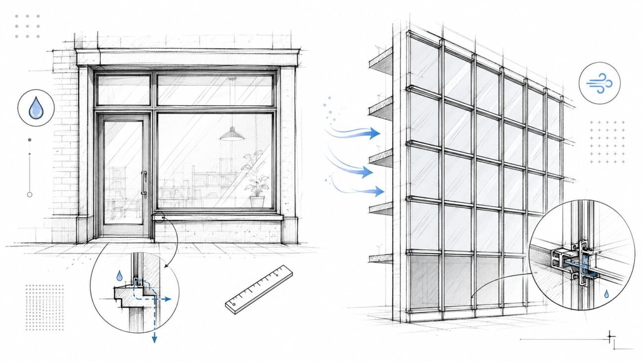
A fire alarm drawing sits at the intersection of architecture, electrical, life safety, interiors, vertical transportation, and mechanical systems. Device locations depend on occupancy, egress, ceiling geometry, room use, and local interpretation. Notification appliances must work with the actual built environment, not the abstract room outline shown early in design.
By permit stage, small misses become visible. The pull station lands in the wrong place because the exit arrangement changed. A smoke detector conflicts with a supply diffuser that moved during HVAC coordination. A strobe ends up above a ceiling feature that was never reconciled. The reviewer sees isolated errors. The production team sees a process gap.
Where teams usually lose control
Most permit headaches don’t come from one major design failure. They come from a string of unresolved minor decisions:
- Late ceiling coordination means device locations are placed before lighting, diffusers, access panels, and soffits are stable.
- Weak sheet-to-model consistency creates mismatches between plans, schedules, and risers.
- Assumed code interpretation causes teams to rely on standard details that don’t match local expectations.
- Unclear design intent handoff leaves production teams guessing what the engineer wanted versus what the architect changed.
Practical rule: If fire alarm layout starts after the reflected ceiling plan is already moving, expect revisions, reviewer comments, or both.
The better approach is to treat fire alarm documentation like any other coordination-sensitive scope. Lock decision points. Verify assumptions. Build the layout against actual ceilings and coordinated trades. Then produce a set that can survive permit review.
That’s especially important when the fire alarm sheets are part of broader permit drawing production workflows. Once these systems are embedded in the permit package, every unresolved detail spreads into review comments, internal redlines, and schedule slip.
The shift from symbols to systems
There’s a useful historical lesson here. A foundational milestone in fire alarm design came in 1852, when Dr. William F. Channing and Moses Farmer developed the first practical telegraph-based fire alarm system in the United States, shifting urban fire response from manual human alerts to automated city-wide electromagnetic signaling, as described in this history of fire alarm development. The core idea was precise location signaling and rapid response.
That basic principle still applies. Modern drawings aren’t just about showing devices. They must communicate exactly what is installed, where it is located, how it interfaces with the building, and how the system responds.
When a set fails permit review, the issue usually isn’t that the team forgot to place symbols. It’s that the documentation didn’t prove the system was thought through.
The Core Components of a Modern Fire Alarm System
A reliable fire alarm layout starts with understanding what the system includes. Non-specialists often focus on detectors and strobes because those are the most visible items on plan. In practice, those devices only make sense when you understand the full system around them.
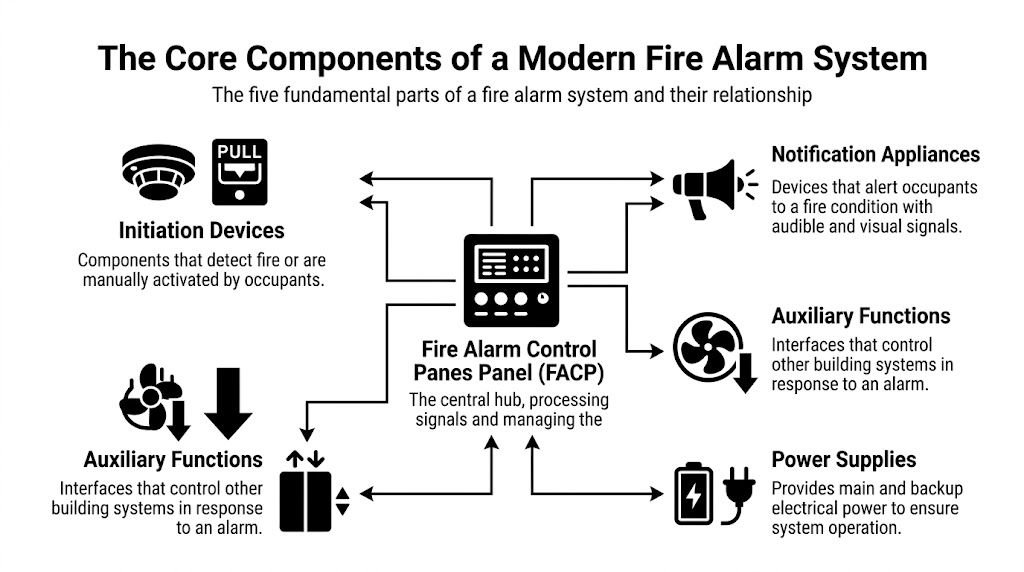
The five parts that matter on every set
Here’s the cleanest way to read a fire alarm scope.
| Component | What it does | Why production teams care |
|---|---|---|
| Fire Alarm Control Panel | Acts as the system hub and processes incoming signals | Drives naming, panel schedules, risers, and room coordination |
| Initiation devices | Detect a condition or allow manual activation | Control spacing, room coverage, and ceiling coordination |
| Notification appliances | Alert occupants with audible and visual signals | Require layout discipline tied to occupancy and room geometry |
| Power supplies | Provide primary and backup power | Affect calculations, panel loading, and equipment coordination |
| Wiring and pathways | Connect devices and system functions | Drive routing, riser logic, and survivability planning |
That list sounds basic, but it’s the structure behind every complete set of fire alarm construction documents.
Fire Alarm Control Panel and system logic
The Fire Alarm Control Panel, often shortened to FACP, is where the system receives inputs and initiates outputs. If a detector activates, a pull station is used, or an interface module changes state, that information lands at the panel and triggers programmed responses.
On the drawing side, the panel is more than a box on a wall. It affects room requirements, equipment clearances, power coordination, naming standards, and circuit organization. If the production team doesn’t know where the panel belongs early enough, the riser and floor plans often drift apart.
A common miss is treating the panel location as a late electrical decision. That usually creates awkward revisions because fire alarm documentation depends on stable panel references.
Initiation devices and where they show up
Initiation devices include smoke detectors, heat detectors, manual pull stations, and interface modules. They don’t all serve the same purpose, and they shouldn’t be laid out with the same assumptions.
- Smoke detectors are common in spaces where smoke detection is required and where ceiling conditions support reliable performance.
- Heat detectors are often used where smoke detection may be a poor fit, such as mechanical or dusty environments.
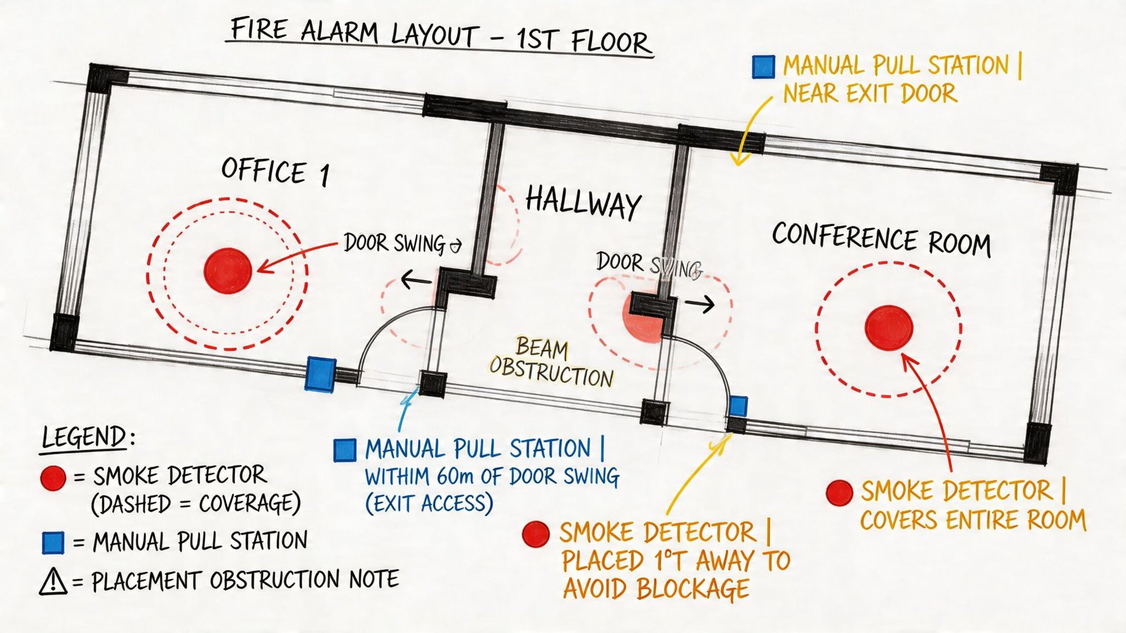
- Manual pull stations are tied to exit strategy and occupant access.
- Interface modules connect the alarm system to related building functions such as door releases, dampers, or elevator recall.
A clean smoke detector layout drawing starts with room use and ceiling conditions, not with a default symbol pattern.
Notification appliances and occupant response
Notification appliances include horns, strobes, horn/strobes, speakers, chimes, and related devices, depending on the building and system type. These are the devices occupants interact with during an event, even if they never touch them.
Production teams usually struggle here when they place devices only for visual symmetry. Fire alarm device placement has to support real coverage and real coordination. A centered strobe that lands in conflict with a light fixture or decorative ceiling element may look good in CAD and fail in the field.
Power supplies and battery backup
Every system needs primary power and backup power. That means battery backup isn’t a side note. It’s part of the documentation logic. Device counts, panel loading, and auxiliary functions all connect back to power.
If the set shows one thing and the calculations assume another, the issue will surface later. Sometimes that happens in review. Sometimes it happens when the installer starts asking questions nobody wants late in the job.
Wiring topology and auxiliary functions
Wiring is where design intent becomes buildable. Teams need to understand not only where devices sit, but how they connect. In modern systems, that includes loops, circuits, pathway considerations, and interfaces with other systems.
Auxiliary functions deserve special attention because they’re often under-documented. A fire alarm system may release hold-open doors, initiate elevator recall, shut down HVAC functions, or signal dampers and control modules. Those actions create coordination points with other sheets and other trades.
Conventional versus addressable systems
A practical distinction matters here. Conventional systems group devices by zones. Addressable systems identify specific devices individually.
For most commercial work, addressable systems are the standard expectation because they support more precise device identification, clearer diagnostics, and better operational visibility. From a documentation standpoint, that precision helps everyone. Reviewers can follow intent more easily. Contractors can map installation with fewer assumptions. Facility teams can identify device-level issues without treating the building like a mystery.
That’s one reason production teams should think of Revit symbols as more than graphics. A modern fire alarm set works best when device identity, schedule data, and circuit logic stay connected instead of being maintained manually across disconnected files.
Navigating NFPA 72 and Local Code Requirements
The fastest way to get fire alarm layout wrong is to treat NFPA 72 fire alarm design as a single-rule exercise. It isn’t. NFPA 72 tells you how fire alarm and signaling systems are designed and operate. It does not act alone. The International Building Code, International Fire Code, accessibility requirements, local amendments, and the Authority Having Jurisdiction all influence what the final layout must show.
Start with the baseline, not the shortcut
For architects and production teams, the practical value of NFPA 72 is that it establishes the operating and placement framework once another applicable code requires the system. That’s an important distinction. Occupancy triggers and building conditions may come from IBC or IFC, while NFPA 72 governs how the devices and signaling system are designed.
A useful external reference is NFPA’s overview of fire alarm basics and applicable codes. The article makes the key point many permit sets miss: teams have to verify the code set, edition, and jurisdictional amendments for the project they’re working on.
That means there is no dependable “copy the last job” workflow for fire alarm plans.
Rules of thumb production teams need to remember
A few layout principles show up repeatedly in review comments and coordination meetings.
- Smoke detector spacing: Flat ceiling layouts are often developed from the familiar 30-foot grid rule of thumb, but actual placement can change with ceiling height, configuration, and obstructions.
- Manual pull stations: These are commonly expected at exits, stair entrances, and along egress paths where occupants can access them on the way out.
- Heat detector use: Mechanical rooms and dusty or dirty areas may justify heat detection where smoke detectors would be a poor choice.
- Notification appliances: Audible and visible notification must align with occupancy needs and accessibility expectations, including strobe performance and sound levels.
None of those rules should be applied mechanically. A clean open office and a high-bay industrial area do not behave the same way, even if the floor plans look simple at schematic level.
The AHJ decides what “acceptable” looks like
Teams often face challenges. A set can appear internally coordinated and still trigger review comments because the local fire marshal or building department interprets code language differently than another jurisdiction did on the previous project.
The AHJ isn’t reviewing your intent. The AHJ is reviewing the set in front of them.
That’s why good production managers push for jurisdiction checks early. If the reviewer expects mounting heights, conduit intent, interface notes, or more explicit device descriptions, those expectations should shape the sheet setup before permit submission.
Code minimums versus nuisance alarm control
Code compliance by itself doesn’t guarantee a good system. A layout can technically satisfy minimum criteria and still perform poorly in the building.
That problem shows up clearly in industrial and high-challenge spaces. Recent industrial case studies indicate that using multi-criteria detectors in appropriate settings can reduce nuisance alarm dispatches by up to 25%, according to this discussion of design strategies for warehouses and industrial sites. The practical lesson is that detector selection and placement should support alarm reliability, not just minimum compliance.
For production teams, that changes the conversation. Instead of asking only “How many detectors fit the rule?” ask “What environment are these detectors serving?” High airflow, dust, humidity, rack storage, and unusual ceiling conditions all matter.
What works in real projects
The most dependable workflow is simple:
- Confirm the applicable jurisdiction and adopted code path.
- Verify occupancy and system triggers before layout begins.
- Use the reflected ceiling plan and room use as live inputs, not background references.
- Resolve local review preferences with the engineer before the permit package is assembled.
- Document interfaces clearly so reviewers and installers can follow the logic.
A team doesn’t need every architect to become a fire protection engineer. It needs enough code literacy to stop preventable mistakes before they reach the sheet set.
Practical Device Layout and Placement Strategy
The code gives boundaries. The building gives reality. Reliable fire alarm device placement happens where those two meet.
Ceiling conditions decide more than most teams expect
A room boundary on the architectural plan doesn’t tell you enough. Device layout depends heavily on the ceiling that will be built.
Flat ceilings are the easy case. Once you introduce sloped surfaces, soffits, beam pockets, clouds, bulkheads, or atrium conditions, detector logic changes fast. A detector that looks centered in plan may land in a poor performing location because the ceiling shape alters air movement or creates pockets that affect detection.
Many non-specialist teams oversimplify. They place devices by room area instead of by ceiling condition. That usually holds until someone overlays the reflected ceiling plan and starts finding conflicts or blind spots.
Occupancy changes the logic, not just the count
Hotels, offices, healthcare spaces, retail shells, storage areas, and assembly functions don’t ask the same questions of the fire alarm system. Initiation requirements differ. Notification expectations differ. Device type and coverage strategy differ.
A healthcare floor, for example, may carry coordination requirements that go well beyond a general office tenant fit-out. A warehouse can introduce ceiling height and airflow issues that make standard spot detector assumptions unreliable. A mixed-use building can stack several layout logics inside the same permit package.
That’s why mature teams don’t start with symbols. They start with a matrix of room use, occupancy expectations, and egress logic.
| Layout driver | What to verify | Typical coordination impact |
|---|---|---|
| Ceiling type | Flat, sloped, obstructed, open, decorative | Shifts detector type and exact location |
| Occupancy use | Office, hospitality, healthcare, storage, assembly | Changes initiation and notification strategy |
| Egress path | Exits, corridors, stair access, lobby transitions | Drives pull station and detection placement |
| System interface | Elevator, HVAC, doors, dampers | Adds modules and cross-trade notes |
Egress paths are not a drafting afterthought
Pull stations and many detection decisions are tied to how people leave the building. If the egress path changes during design development and the fire alarm sheet doesn’t change with it, the problem is already in the set.
That’s one reason corridor, stair, and exit coordination should be treated like a checkpoint. Fire alarm teams should not be working from stale egress geometry.
A lot of permit comments that look like code failures are really update failures. The path changed. The fire alarm plan didn’t.
The reflected ceiling plan is where good layouts survive
The reflected ceiling plan is the ultimate proving ground for a smoke detector layout drawing. A detector may satisfy spacing in abstract plan view and still be wrong once the actual ceiling is modeled.
Production teams need to check device placement against:
- Lighting fixtures that block ideal device locations
- HVAC diffusers and returns that can create poor detector performance zones
- Sprinkler heads that compete for ceiling real estate
- Access panels that should remain clear
- Structural elements such as beams or transfer conditions
- Architectural features including clouds, reveals, and decorative alignments
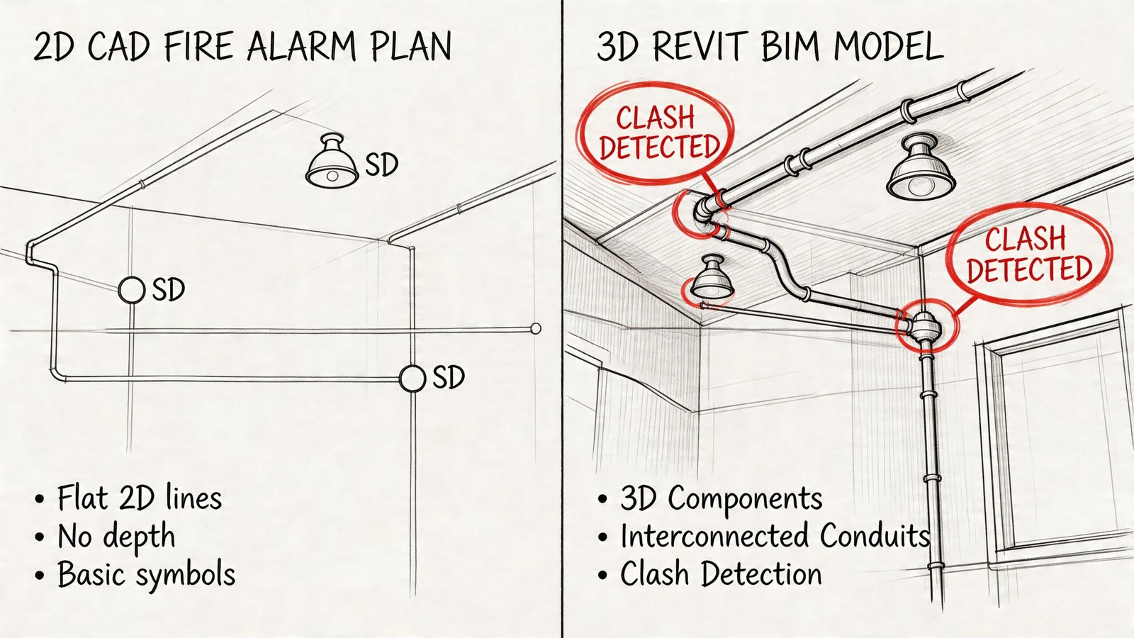
When that coordination happens in 2D only, people miss things. Not because they’re careless, but because stacked overlays and visual memory are weak quality-control tools.
Interfaces are where hidden clashes live
Fire alarm systems often control or monitor other building functions. Door hold-opens, smoke dampers, elevator recall, and HVAC shutdown all create detail that doesn’t always appear on the first pass of the floor plan.
These interfaces matter because they add modules, notes, wiring logic, and room-specific coordination. If the system releases doors, those doors need to be identified. If the system initiates elevator recall, the interface path has to be documented clearly enough for the project team to build and review it. If dampers are involved, the mechanical sheets and control narratives need to line up.
What a mature placement workflow looks like
The most reliable teams use a repeatable sequence instead of dropping devices room by room in a rush.
- Verify room use and occupancy assumptions before any layout begins.
- Overlay current reflected ceiling plans and flag unstable areas.
- Place initiation devices based on space conditions, not visual symmetry.
- Lay out notification appliances with accessibility and ceiling coordination in view.
- Check egress-related devices after all door and exit revisions are current.
- Add interfaces and module points with clear cross-trade references.
- Run a QA pass that compares plans, schedules, risers, and details for consistency.
That process is slower at the front end and much faster by permit and installation. That’s the trade-off most firms eventually learn the hard way.
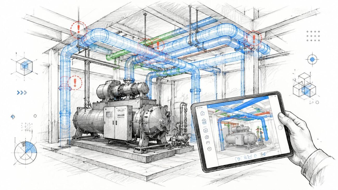
Why BIM is Essential for Fire Alarm System Design
A permit set can look clean in plan view and still fail in production. The schedule says one thing, the riser says another, ceiling conditions changed two weeks ago, and the door release interfaces were updated on electrical notes but never reflected in the fire alarm sheets. That is where margins disappear. BIM helps control those handoff points before they turn into review comments, redesign hours, and field questions.
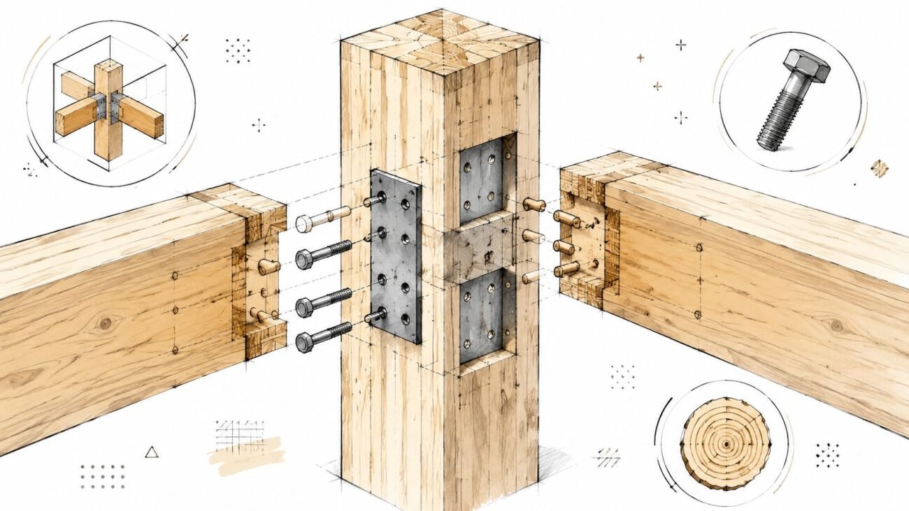
Revit families should carry production data
A usable fire alarm model does more than place symbols on a background. Well-built fire alarm Revit families can hold device type, description, address parameters, circuit assignment, mounting data, zone information, and schedule fields. That gives the team one controlled source for plan graphics and documentation output.
The practical benefit is consistency. If a horn-strobe changes to a speaker-strobe, that revision should flow into the schedule and tags through the model, not depend on someone catching three separate drafting edits late at night. BIM does not remove QA. It gives QA a cleaner system to check.
BIM reduces coordination failures that 2D workflows miss
Fire alarm sheets sit in the middle of several trades. Ceilings shift. Mechanical diffusers move. Door hardware changes. Elevator interfaces get revised after architectural updates. In a mature BIM workflow, those changes are easier to see and harder to ignore because the design team is working inside coordinated building information instead of disconnected backgrounds.
That matters most on projects with repeated revisions. A 2D workflow can still produce a permit set, but every manual update increases the chance of drift between plans, schedules, details, and risers. BIM cuts that exposure by keeping more of the documentation logic tied to actual model elements.
Firms evaluating model-based delivery usually see the same pattern described in this overview of the benefits of BIM modeling. Better information structure leads to fewer preventable coordination misses.
The real gain is production maturity
Clash review is useful, but it is not the main reason experienced teams use BIM for fire alarm documentation. The bigger gain is a repeatable production system.
A mature setup includes standardized families, shared parameters, view templates, schedule rules, sheet conventions, and QA checks that compare model output against design intent. That is what makes permit-ready work more predictable across different project types, different staff, and different deadlines. Without that structure, BIM becomes expensive drafting in 3D.
This is also where BIM supports better BIM-to-permit workflows inside AEC firms. The model becomes the operating system for documentation, not a side file built for presentation.
Schedules and risers get cleaner when the model is built correctly
Fire alarm packages often break down in the secondary views. Floor plans may look acceptable while schedules are incomplete, risers lag behind revisions, or device tags stop matching the current layout. Model-based documentation helps prevent that because schedules and tagged views are generated from the same object data used in the plan.
The result is not automatic perfection. Bad families and weak standards still create bad sheets. But when the underlying model is structured correctly, revision management gets faster and less risky, especially on multi-floor buildings, phased renovations, and projects with repeated room types.
LOD should match the handoff
Some projects only need permit-level documentation. Others need deeper trade coordination before procurement and installation. The fire alarm model should reflect that difference.
For coordination-heavy work, an LOD 350 model can add real value by showing mounting intent, interface locations, pathway considerations, and cross-trade visibility with enough clarity to support reviews. For simpler jobs, that level of detail may waste time and fee. Good production managers set the model scope to match the deliverable, then enforce that scope consistently.
BIM is a process choice
The important decision is not software preference. It is whether the firm wants fire alarm documentation produced through a controlled information model or through isolated drafting tasks that depend on memory.
Reliable teams choose the first option because it lowers rework, shortens revision cycles, and gives permit reviewers a package that reads as one coordinated set instead of several loosely related files.
Avoiding Common Mistakes and Leveraging Production Partners
A fire alarm set can look clean at 60 percent CD and still fail in permit review because three small production checks never happened. The detector layout was drafted on an outdated reflected ceiling plan. A few room use changes never made it into the device count. The riser and battery assumptions were never reconciled with the final floor plan. That is how a manageable scope turns into review comments, revision churn, and field questions that burn fee.
Mistakes that trigger review comments and field rework
The recurring failures are rarely technical mysteries. They usually come from gaps in production control, model hygiene, or review sequencing.
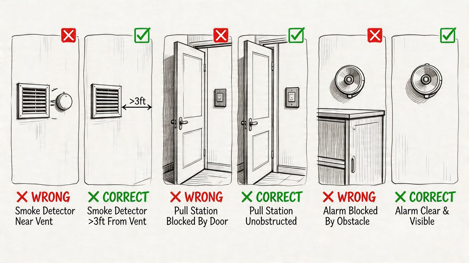
- Dead-air placement: Smoke detectors placed too close to walls or in poor airflow conditions create avoidable performance and review issues. A common red flag is placing them within 4 inches of a wall or too close to HVAC devices.
- Missed rooms and transition spaces: Storage rooms, mechanical areas, elevator lobbies, and similar spaces get skipped when room functions change late and the fire alarm background is not refreshed.
- Ceiling conflicts: Strobes and detectors end up fighting for the same ceiling zone as lights, diffusers, access panels, or grid breaks because nobody ran a coordinated ceiling pass before issue.
- Battery and circuit mismatches: The shown device count does not match the load assumptions, NAC strategy, or panel arrangement shown elsewhere in the set.
- Incomplete permit detail: Some jurisdictions want explicit conduit routing, mounting heights, interface notes, or sequence references that the team assumed the contractor would sort out.
These are production failures. They are also margin failures.
Why these misses get expensive
The first correction is usually cheap. The second and third are not.
Once the set is out, one missing decision turns into engineer markups, revised backgrounds, updated schedules, coordination calls, and installer questions. If the package was built in disconnected files instead of a controlled BIM workflow, each revision has to be checked by hand. That is where small fire alarm errors start affecting the whole job, especially on multi-floor work and renovation projects with changing existing conditions.
As noted earlier, industry research has tied rework to a meaningful share of total project cost. Fire alarm documentation contributes to that problem because it touches architecture, power, ceilings, doors, elevators, and mechanical interfaces all at once.
The review structure that prevents repeat mistakes
Reliable teams do not depend on one experienced designer catching everything from memory. They set review gates that match how the documentation is produced.
| Production checkpoint | What gets reviewed |
|---|---|
| Background validation | Current architectural plans, room names, ceiling types, and reflected ceiling plans |
| Layout QA | Detector spacing logic, pull station path, notification coverage intent, and device type consistency |
| Coordination pass | Conflicts with lighting, HVAC, sprinklers, structure, access panels, and door hardware interfaces |
| Documentation review | Tagging, schedules, risers, details, notes, mounting references, and cross-sheet consistency |
| Pre-issue review | Jurisdiction-specific requirements, sheet completeness, and Engineer of Record markup closure |
A mature production team also defines who owns each check. That matters. If everyone is “reviewing coordination,” nobody is accountable when the strobe lands on top of a diffuser or a renamed room disappears from the device schedule.
Where a production partner actually helps
A good production partner does more than add drafting capacity. The value is control.
On many projects, the architect or MEP engineer keeps design authority, client communication, and final technical decisions. The production partner supports execution through model setup, device placement from defined criteria, sheet development, coordination views, risers, schedules, and permit-ready documentation. The Engineer of Record or fire protection engineer retains stamping authority. That line needs to stay clear in kickoff notes, markups, and final issue procedures.
The better arrangement is operational, not transactional. A production partner should work inside the firm’s standards, naming rules, family strategy, QA gates, and BIM execution requirements. That gives the team a repeatable output instead of a stack of drafted sheets that still need to be rebuilt internally. Firms that treat outside support as an extension of production maturity usually get faster review cycles and fewer late surprises.
That discipline also carries into downstream detailing. On projects that continue into installation coordination, early alignment with fire alarm shop drawing support workflows reduces redraw effort and preserves the logic established in the permit set.
Conclusion The Path to Predictable Fire Alarm Documentation
Fire alarm drawings only look simple from a distance. Up close, they are one of the clearest tests of whether a project team is managing coordination well or just hoping the permit reviewer and contractor fill in the gaps.
Reliable fire alarm system design and device layout depends on a few habits. Use current architectural backgrounds. Read occupancy and egress conditions carefully. Coordinate against reflected ceiling plans, not generic room outlines. Treat interfaces with doors, elevators, and HVAC as part of the system, not side notes. Build the documentation in a structured environment where schedules, tags, and plan content stay aligned.
That’s why BIM matters here. It helps teams move from symbol placement to controlled production. It improves visibility, catches conflicts earlier, and supports documentation that can hold up under permit review and field scrutiny.
For small and mid-sized AEC firms, this is less about chasing technology and more about protecting margin. When fire alarm drawings are produced with discipline, teams reduce redlines, avoid preventable RFIs, and hand off clearer information to the engineer, reviewer, and installer. When the process is loose, the job pays for it later.
A lot of firms don’t need another lecture on code. They need a workflow that turns code requirements and design intent into predictable deliverables. That’s the difference between box-checking and production maturity.
If your team wants a clearer process for coordinated fire alarm documentation, BIM Heroes can help with project assessment, production support, and BIM-based workflows that make permit sets more predictable. If it’s useful, ask for a framework, checklist, or a practical review of where your current process is creating avoidable risk.
Category: BIM Technology & Workflows