Meta description: A practical guide to load paths in truss design for architects and project managers. Learn how trusses carry load, where coordination breaks down, and how to reduce RFIs, redesign, and field changes.
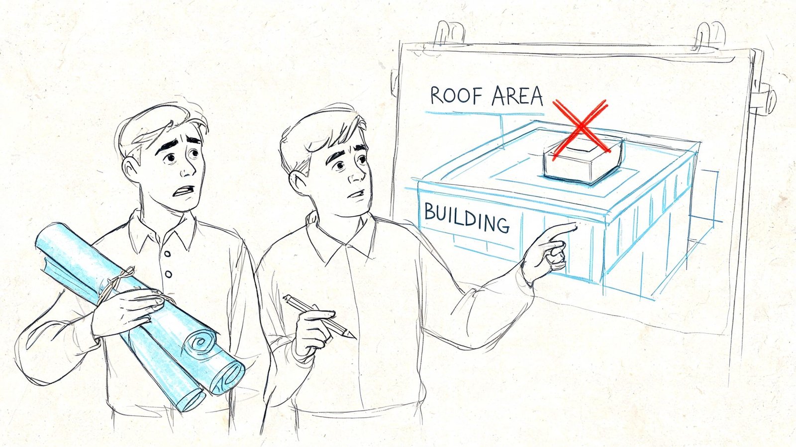
A familiar problem shows up late. The roof plan is mostly settled, the reflected ceiling plan is moving, and then structural review comes back with a hard stop. A rooftop unit was added after the truss layout was coordinated. A partition was shifted under a floor or roof truss. A lighting support detail landed where the engineer never intended to take load. Suddenly the issue is not one change. It is a chain reaction through the truss.
That kind of revision usually gets framed as a structural problem. In practice, it is often a coordination problem first. The architect did not need to size the truss, but the team did need enough literacy to understand how the truss was carrying load before moving things around it.
That is why load paths in truss design matter to architects. Not as an engineering exercise, and not as permission to make structural decisions alone. As production literacy. If your team understands where loads enter, how they move, and where they leave the truss, you catch more conflicts in model coordination, ask better questions earlier, and avoid expensive changes after permit or fabrication.
Introduction
Architects run into truss issues because trusses look simple in elevation and behave with more complexity in the model. A clean roof line can hide a very specific structural logic. Move one support, hang one new load, or interrupt one member, and the whole conversation changes.
For architectural project managers, that matters because truss-related revisions rarely stay contained. They trigger redraws, engineer responses, shop drawing comments, and field clarifications. When teams are trying to protect fee and schedule, that is exactly the kind of avoidable churn that hurts margin.
Field lesson: Most truss coordination problems do not start with bad intent. They start with one reasonable design move made without a clear view of the load path.
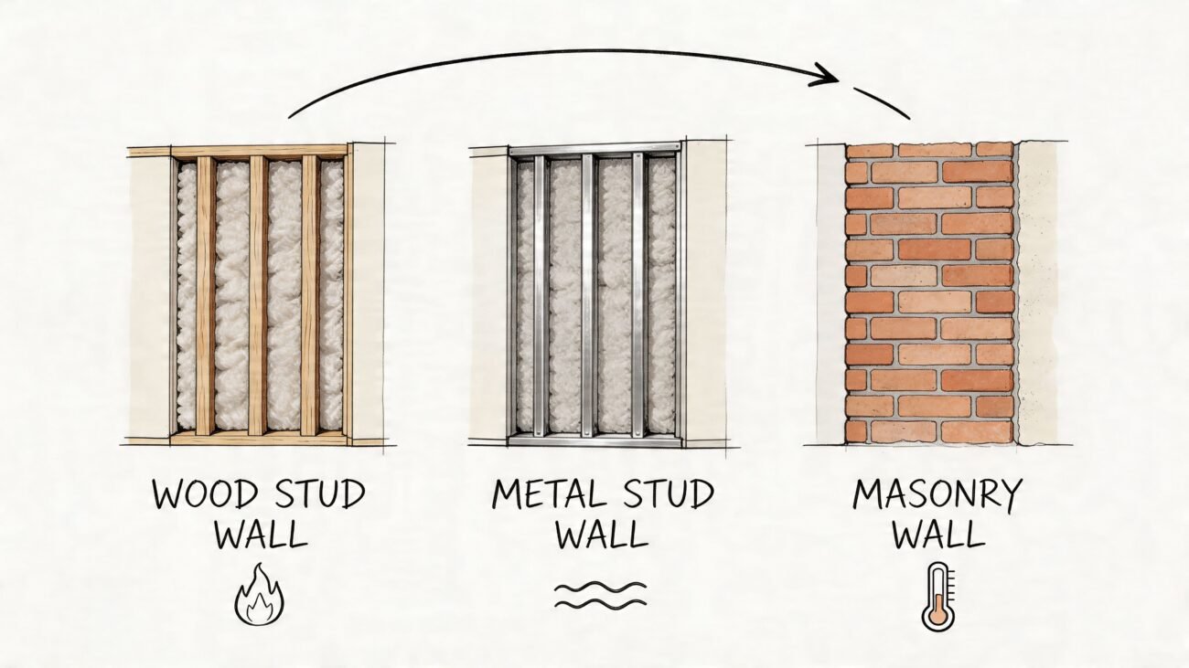
What a Load Path Is and Why It Matters in a Truss
A load path is the route forces take from where they are applied down to the foundation. That includes dead loads such as the self-weight of materials, live loads from occupants or movable items, and environmental forces such as wind, snow, and seismic action. A continuous and direct load path is foundational for safety because interruptions can redirect forces into unintended areas, as explained in Turn2Engineering’s overview of load path analysis.
In a simple beam, the path is easy to picture. Load lands on the beam, the beam transfers it to supports at each end, and the supports pass it down. Most architects can read that condition almost instinctively.
A truss is different. The load doesn’t move through one solid member. It moves through a network of chords and web members, each doing a specific job. Some members carry compression. Others carry tension. Connections matter because the force is being handed from one element to another, not just absorbed by a single spanning piece.
Why architects need this concept
For architecture teams, the practical issue is straightforward. Every design decision that changes where load is applied, or interrupts how it moves, can change the behavior of the whole truss. That includes items architects deal with every day:
- Roof scope changes such as heavier roofing, screens, solar arrays, or added curbs
- Interior revisions such as moving partitions, adjusting ceiling support, or adding suspended equipment
- Coordination edits such as opening sizes, framing shifts, and late MEP routing decisions
A truss can look forgiving because it is made of many members. In practice, it is often less forgiving because those members depend on each other.
Beam logic versus truss logic
Here is the useful distinction for truss design for architects:
| Condition | How load behaves | Coordination takeaway |
|---|---|---|
| Simple beam | Load follows a direct route to end supports | Most changes are local and easier to visualize |
| Truss | Load distributes through multiple members and nodes | A local change can create system-wide consequences |
That is why structural load path architecture is not just an engineer’s concern. It is part of drawing discipline, model review, and early decision-making.
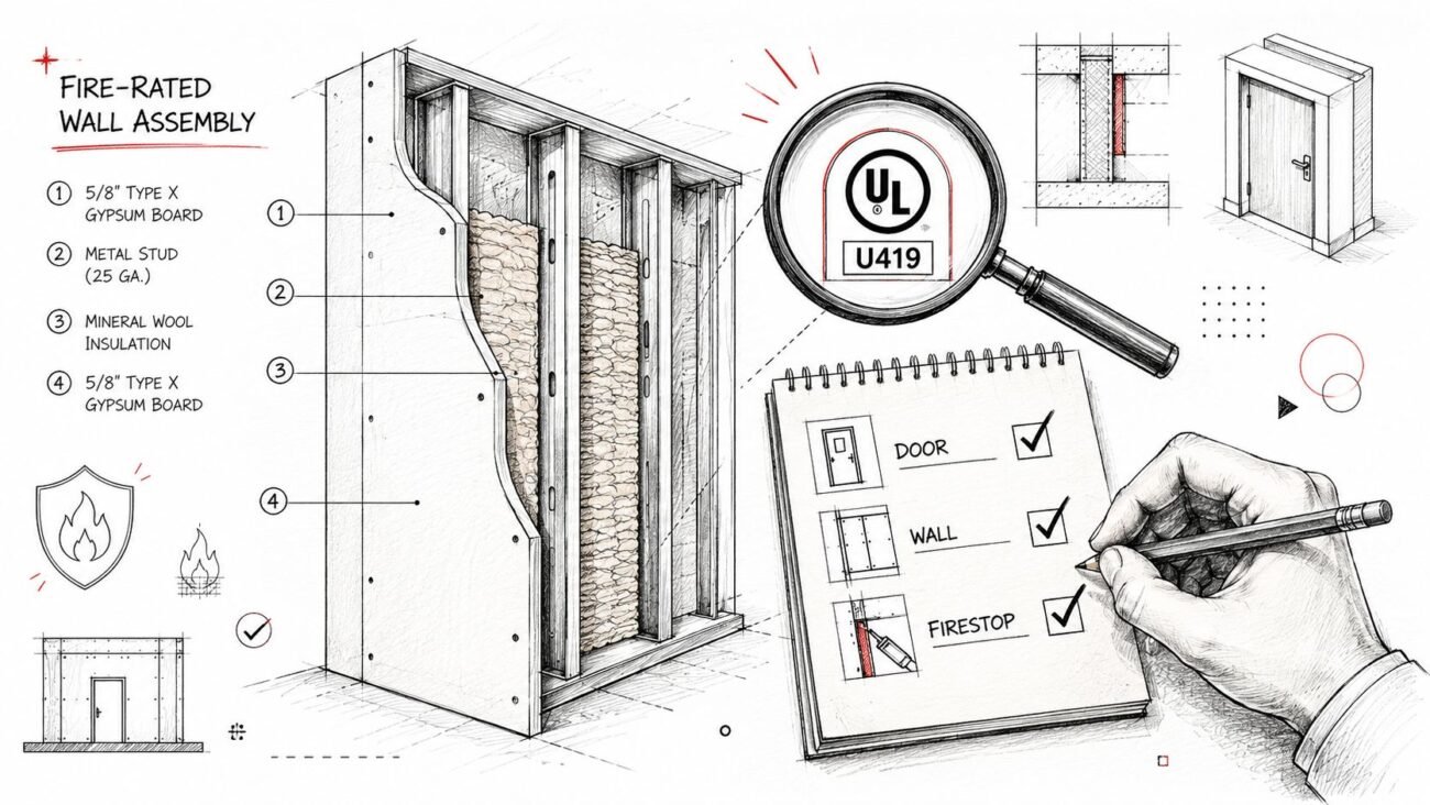
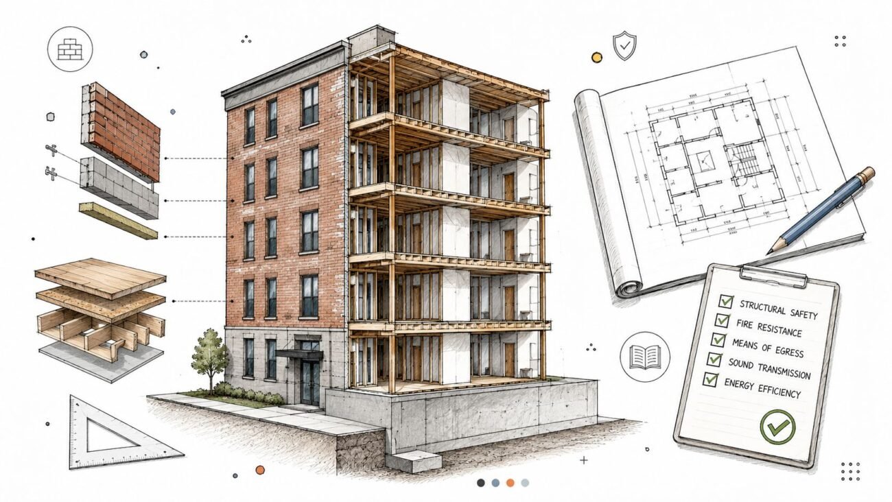
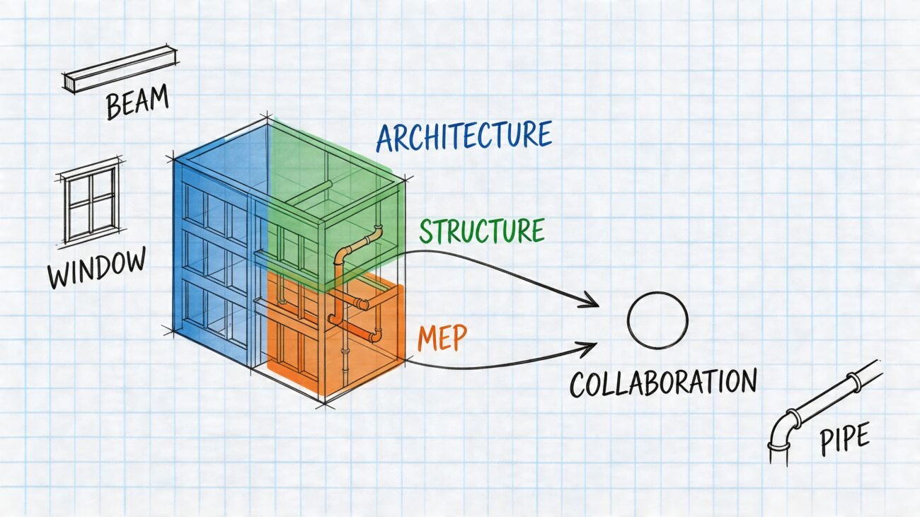
Truss Anatomy for Architects
If architects are going to coordinate trusses well, they need a reliable mental map of the pieces. Not for calculation. For recognition.
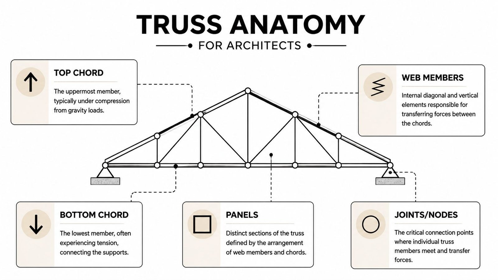
The top chord is the upper continuous member. Under gravity loading, it is typically in compression. Roof decking, purlins, or sheathing often attach here, so changes above the truss usually start affecting this zone first. If someone proposes a penetration, bearing shift, or localized equipment support here, that is not a drafting note. It is a structural conversation.
The bottom chord is the lower continuous member and is typically in tension. Architectural and MEP pressures often become apparent here. Ceiling attachments, light supports, access panels, and duct routing all seem to want the same space. In production, teams become casual, and problems frequently arise at this stage.
The parts that usually drive coordination comments
The web members are the diagonal and vertical internal pieces between chords. Their pattern determines how force transfers inside the truss. If a plumber or duct installer wants to “just trim one,” they are not adjusting dead space. They are altering the load path.
The panel points are the nodes where members connect. These are especially important in roof truss coordination because loads are generally intended to land at these points. When loads land between panel points, the chord can see bending it may not have been designed to take.
The bearing points are where the truss meets its support, such as a wall, beam, or column. If a bearing condition changes, the upstream geometry may still look fine in Revit, but the structural behavior has changed.
A good architectural model shows more than outline geometry. It makes support conditions, panel logic, and member locations visible enough to coordinate against.
What to look for in the model
When reviewing trusses in BIM, architects should be able to answer a few simple questions fast:
- Where does the truss bear. On walls, beams, or columns?
- Where are the panel points. Can added loads align with them?
- What occupies the bottom chord zone. Ceiling systems, ducts, lighting, signage?
- Which members are likely to get challenged by openings or penetrations
This is one reason teams benefit from disciplined framing representation early in the model. A polished plan set is not enough if the geometry is too abstract to coordinate. Clear framing documentation in Revit helps teams spot these conflicts sooner, especially when the architectural team is developing ceilings and soffits alongside structure. A good example of that production mindset shows up in this guide to a framing plan in Revit.
How Loads Actually Travel Through a Truss
Trusses work by taking what looks like a single roof or floor load and distributing it through a system of members. For gravity conditions, the load usually enters through the top chord or at panel points connected to it. From there, the force moves through the web members and resolves at the bearings.
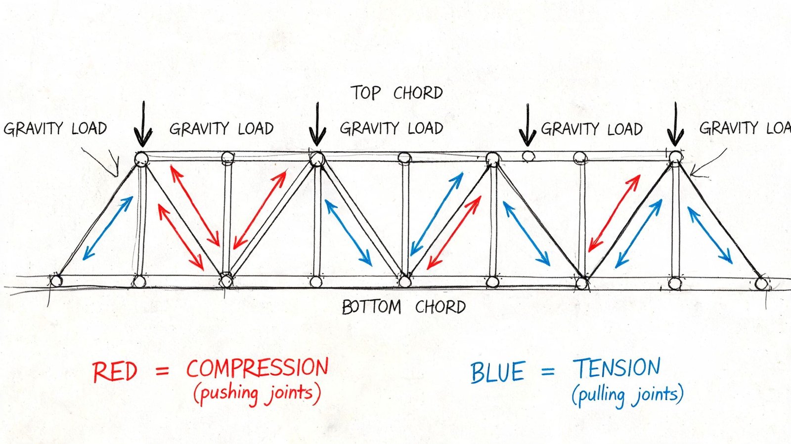
That description sounds abstract until you connect it to what happens physically. Under gravity load, the top chord typically shortens in compression. The bottom chord typically elongates in tension. The web members sort out the internal transfer between those two conditions. That is why a truss can span efficiently with relatively slender members. Each piece is being asked to do a targeted job.
Distributed loads and point loads are not the same
A broad roof load, like roofing and sheathing, behaves differently from a concentrated load, like a unit support or a post above. Architects feel this difference in coordination even if they never calculate it.
A distributed load is spread along the roof system. A concentrated load hits one location. The truss may be designed to take both, but not in the same place and not in the same way. If a concentrated load lands where the engineer expected it, the truss can route it through its intended force path. If that same load lands off the expected node, the chord can start acting in bending instead of mainly axial action.
The panel point issue
This is one of the most useful ideas for architects to carry into coordination meetings. Loads should be applied at panel points, not casually between them, especially in lighter truss systems.
When a load lands at a panel point, it enters the truss at a connection that is already set up to transfer force through the web system. When a load lands between panel points, the member receiving it can see a local bending condition that was not part of the original intent.
That is why the phrase “it’s not that heavy” is not a safe structural judgment. A modest load in the wrong place can be more problematic than a larger load in the right place.
Practical rule: Before adding anything above or below a truss, find the panel points first. If the proposed load does not align with one, ask the engineer before the detail gets baked into the set.
Trusses inside larger roof systems
Architects rarely deal with one isolated truss. They deal with a roof system. Hip conditions, valley framing, truss girders, and hybrid steel-wood conditions make the path more layered. One truss may carry another. One member may collect load from tributary framing that is not obvious in a clean architectural section.
That is where structural coordination BIM earns its keep. Model-based overlays help teams see when the architectural idea and the structural route are starting to diverge. The same applies to lateral behavior. Vertical gravity loads and lateral loads do not follow the same route, and misaligning them can create hidden vulnerabilities. As the Institution of Civil Engineers notes, lateral load paths resisting wind often use systems such as shear walls and cores, which follow a different route than vertical gravity loads in the structure. Their article on structural load paths is a useful reference for that distinction.
Common Truss Types and Their Coordination Implications
Not all trusses create the same coordination pressure. The geometry changes the way space can be used, where services fit, and how forgiving the structure is when design changes arrive late.
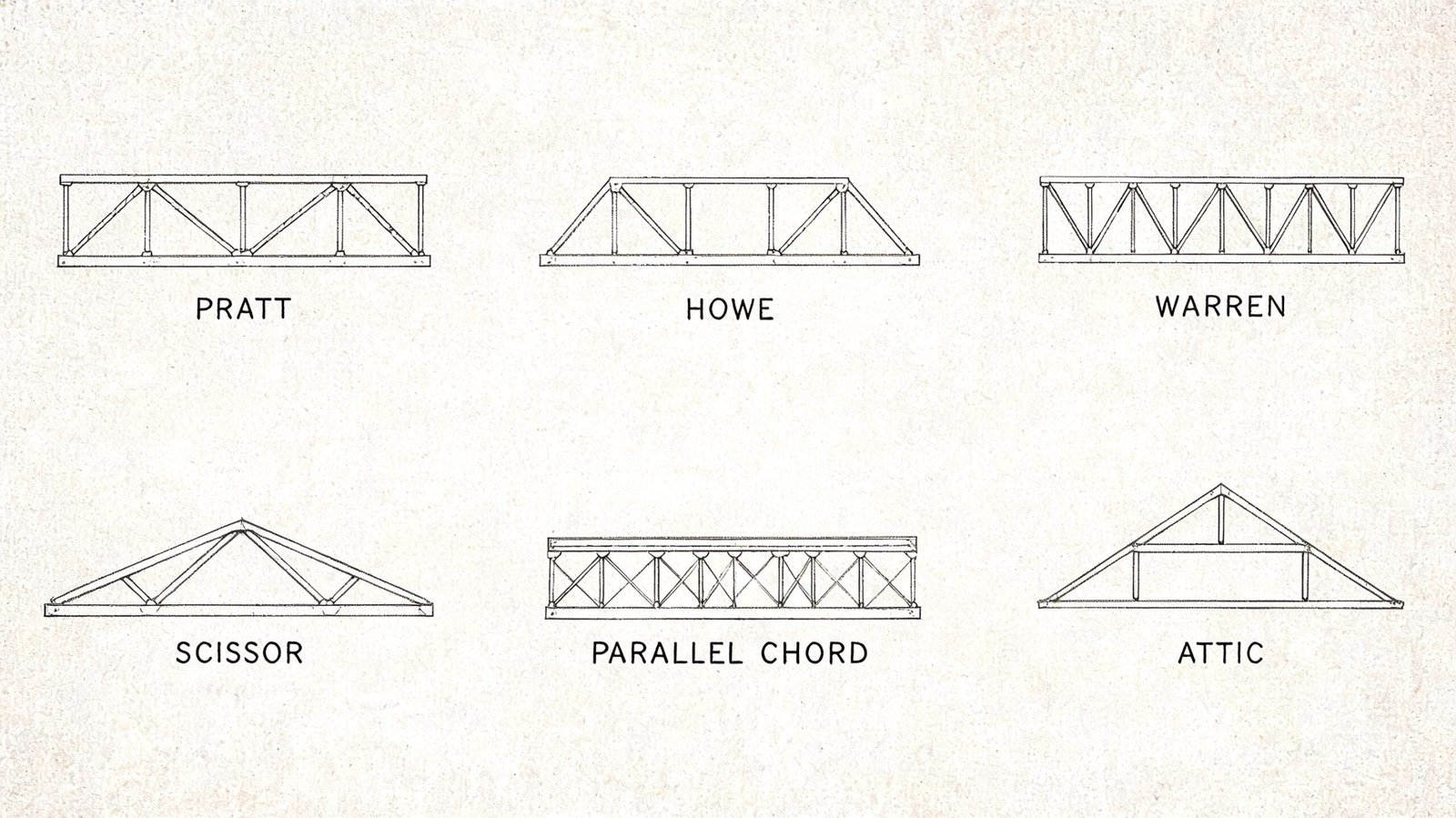
Pratt and Howe
A Pratt truss typically uses vertical web members in compression and diagonals in tension. Architects often see it in longer-span applications because the geometry is efficient and legible. The coordination implication is usually about understanding where those diagonals are heading so openings, glazing alignments, or suspended elements do not fight the web pattern.
A Howe truss reverses that logic, with diagonals typically in compression and verticals in tension. It shows up less often in current mainstream work but still appears in some building types and in existing conditions. On renovation projects, teams can get in trouble by assuming one truss web pattern behaves like another just because the silhouette looks familiar.
Warren
A Warren truss uses a repeating triangular pattern, often without vertical web members. It can look clean and attractive when exposed, which is one reason architects like it. The coordination issue is that panel points can be farther apart, so ceiling attachments or suspended loads have fewer obvious places to land cleanly.
In exposed conditions, that matters twice. The structure is doing the work, and the structure is also on display. Late support clips and improvised field hangers usually look bad and signal that coordination happened too late.
Scissor and parallel chord
A scissor truss gives architects the vaulted ceiling profile many projects want. The rising bottom chord creates volume, but it also constrains what can happen inside that volume. HVAC routing, lighting alignment, and ceiling support all need to respect that geometry. Teams often underestimate how quickly a simple reflected ceiling concept stops working once actual truss depth is modeled.
A parallel chord truss keeps top and bottom chords parallel, which makes it common in flat or low-slope roofs and floor systems. It is predictable from a coordination standpoint, but the fixed depth can become the limiting factor when floor-to-floor space is tight or MEP congestion is heavy.
Attic and girder conditions
An attic truss creates usable space within its depth by opening the center zone. Architects are naturally drawn to that usable volume. The coordination trap is assuming that because space exists inside the truss, the members around it are negotiable. They are not. In these conditions, the structure defines the usable envelope, and modifications need engineer review.
A truss girder is less a style than a role. It carries other trusses. When it appears in the system, downstream roof geometry depends on it more than many architectural teams realize. If its location shifts for planning reasons, the ripple effect is rarely local.
For firms working through industrial and large-span roof layouts, these issues become very visible in planning and section development. Warehouse work is a good example because truss or long-span roof coordination often intersects with equipment, lighting grids, and clear-height requirements. This is where architectural intent and structural logic need to stay aligned from the start, especially on projects like warehouse architecture.
Where Architects Most Commonly Create Load Path Problems
The biggest load path mistakes are usually ordinary design moves made too late or made without a clear communication loop. They are not exotic failures. They are routine scope changes that nobody translated into structural consequences soon enough.
Late-added loads
Rooftop mechanical equipment is one of the most common examples. A unit gets added during design development or CDs, and the team treats it like a coordination item instead of a structural input. The same pattern shows up with screens, solar components, and suspended specialty equipment. The issue is not whether the item seems small. The issue is whether the truss was designed for that load at that location.
Another common miss is the cumulative effect of many small hanging loads. Ceiling systems, decorative fixtures, ducts, diffusers, and support steel can all end up bearing on the bottom chord zone. Each item may look harmless in isolation. Together, they can create a condition the original truss designer did not assume.
Member interruptions
Cutting or notching truss members is where field convenience collides with structural reality. Bottom chords get challenged by duct routes. Web members get challenged by piping. An installer sees a conflict and thinks in terms of clearance. The truss was designed in terms of force transfer.
That mismatch is why architects need to document no-cut expectations clearly and why coordination needs to happen before fabrication and field layout.
If a member is carrying load, it is not spare material. It is part of the route the force is taking.
Support and layout changes
Partitions are another repeat offender. A wall moved for planning reasons can end up bearing where the truss was not intended to take a concentrated load. The same applies when value engineering removes or shifts a support condition that was helping the structural system work.
Assuming symmetry creates a different kind of error. Hip roofs, valleys, and irregular plans often produce asymmetric loading. An architectural team may think the framing is mirrored because the roof looks mirrored. The actual load path may not be.
Why continuity matters
The stakes here are not only budget and schedule. They are also safety. The 1985 Hyatt Regency walkway collapse killed 114 people because a change in connection design created a discontinuous load path and doubled the stress on a critical connection, a failure that directly led to code changes mandating continuous load paths, as summarized in this load path analysis reference.
That event is not a warning that architects should engineer trusses. It is a reminder that discontinuous load paths are serious. On ordinary projects, the consequences usually show up first as RFIs, redesign, and shop drawing churn. But the underlying principle is the same. If the load path is broken, the problem is real whether it appears in review comments or in the field.
How to Improve Truss Coordination with Engineers
Good coordination around trusses comes from process, not heroics. Teams that do this well build decision checkpoints into the workflow before fabrication pressure takes over.
Habits that reduce rework
- Ask for design assumptions early. If the project includes trusses, get the structural design loads and support intent before the architectural team fixes equipment, ceiling, or partition decisions.
- Request panel point visibility. If panel points are not clear in the structural set or model, ask for them. Architects do not need to calculate from them, but they do need them for coordination.
- Flag every new load formally. If a rooftop unit, heavy fixture, partition, or support frame was not in the original structural conversation, route it back through the engineer.
- Overlay models before release. Exposed trusses and tight roof zones need model-based checking against lighting, ceilings, and MEP systems before fabrication.
The better working relationship
The most productive architect-engineer relationships are not review-based. They are checkpoint-based. The structural engineer should not first hear about a new truss load during permit comments or after an RFI from the field.
A useful way to frame it is through the design principles of clarity, continuity, and redundancy. Direct routes matter. Smooth transitions matter. Alternate routes matter. Poor transitions, such as missing footings or misaligned posts, are a common cause of broken load paths, as discussed in CivilEra’s article on understanding load paths in structural design. For production teams, that translates into cleaner handoffs, clearer models, and fewer assumptions hiding in the background.
If coordination friction keeps repeating across disciplines, it usually means the workflow needs adjustment, not just another round of comments. Teams dealing with recurring clashes and unclear ownership often need to tighten their review sequence and issue tracking around known problem zones. A structured approach to coordination issues can then prevent the same truss conflicts from reappearing project after project.
Conclusion
Architects do not need to become structural engineers to work well around trusses. They do need enough load path literacy to recognize when a design move changes how force travels through the system. That is the difference between a smooth coordination cycle and a late structural surprise.
When teams understand load paths in truss design, they make better decisions earlier. They ask smarter questions, model more accurately, and avoid revisions that burn time after permit or fabrication. That kind of literacy protects design intent, project predictability, and fee.
If your team is coordinating complex roof trusses and needs reliable 3D truss geometry in Revit to catch conflicts before they hit the field, BIM Heroes handles that production work with the kind of model discipline that supports cleaner coordination, fewer RFIs, and more predictable delivery.
Suggested WordPress category: BIM Technology & Workflows