Meta description: A practical guide to building a Revit workflow for modular housing manufacturers that supports repeatable production, factory drawings, permitting prep, MEP coordination, and scalable product-line control.
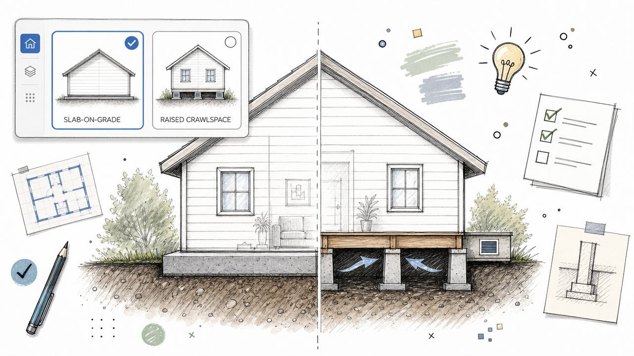
Most Revit environments are built for one building, one site, one permit set, and one construction sequence. That logic works for custom homes and conventional project delivery. It starts breaking the moment a modular manufacturer tries to run a factory with a handful of repeatable unit types, finish options, porch variants, panel assemblies, and state-specific submission requirements.
This is the core mismatch behind much avoidable pain in modular housing. Teams copy a project file, rename it, adjust a few dimensions, and call it efficient. It isn't. It creates drift across “identical” products, bloats file management, weakens QA, and makes every late change more expensive than it should be.
The pressure to fix this is only getting stronger. The global modular construction market was valued at USD 111.1 billion in 2025 and is projected to reach USD 207.8 billion by 2033, growing at a CAGR of 8.2% according to Grand View Research's modular construction market analysis. Growth at that pace forces manufacturers to move past ad hoc modeling and into production systems.
A workable Revit workflow for modular housing manufacturers starts with a different assumption. You're not building a better project template. You're building a controlled production model, a parametric unit-type library, and a documentation structure that can serve both the plant and the field without confusion.
Introduction
The usual signs show up fast. A plant launches with a clean Revit template borrowed from a site-built workflow. The first model goes fine. The second needs option swaps. The third needs a code-driven tweak in one state, a porch revision in another, and a finish package update across the line. Within a few cycles, the team is managing copies of copies.
That approach can limp through a few jobs. It won't support a production line.
In modular housing, the same base unit may move through the factory repeatedly with controlled variation layered on top. That changes everything. File structure, family strategy, decision checkpoints, drawing logic, QA, and revision control all need to reflect repeatability instead of one-off delivery.
The strongest teams stop thinking in terms of “project model first.” They think in terms of product definition first.
Practical rule: If a change to one standard unit can't be assessed centrally before it hits active models, the workflow isn't production-ready.
What works is a system that separates stable product data from job-specific scope, locks approved content for production, and pushes variation through parameters instead of remodeling. That's the shift that protects margin and prevents the small inconsistencies that turn into RFIs, fabrication errors, and field delays.
Why Standard Revit Workflows Fail in Modular Production
A standard project workflow assumes a single building with a single drawing set and a single delivery path. Manufacturing doesn't work like that. A modular plant reuses the same unit logic repeatedly, and only part of the package is project-specific.
That difference sounds obvious, but many teams still treat modular housing like a larger custom-home office. They clone files, create isolated variants, and let separate model lines evolve independently. The result is predictable: duplicated effort, conflicting dimensions, and no reliable way to update active production content without manual cleanup.
The broader industry is already leaning on BIM. Over 60% of modular projects in 2024 utilized Building Information Modeling, and those workflows can reduce project timelines by 30–50% compared to conventional methods when the setup is optimized for manufacturing according to Market Growth Reports on the modular homes market. The key phrase is optimized for manufacturing. A site-built template with a few extra views doesn't qualify.
The common failure pattern
Most breakdowns follow the same sequence:
- Copied unit files drift apart: one team member adjusts a panel depth in one model, another edits window offsets elsewhere, and “standard” units stop being standard.
- Options become geometry edits: instead of toggling approved parameters, teams remodel porches, openings, and finish-dependent conditions by hand.
- Revisions don't propagate cleanly: one code update or rough-in change has to be hunted down across multiple live files.
That's where margin disappears. Not in one dramatic error, but in repeated small decisions that force redraw, rechecking, and re-approval.
For manufacturers trying to build stronger digital discipline around production, this is also where adjacent systems matter. Document control, permissions, and dependable access aren't side issues. They shape whether the team can hold a locked standard. That's also why operations leaders often look at resources on choosing an MSP for construction when they tighten up plant-side delivery systems.
A cleaner path is to treat the product line as a managed asset. That's the operating logic behind disciplined modular construction design services, even when the plant and design team are handling much of the work internally.
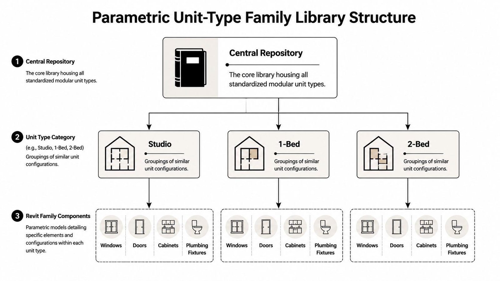
Building a Parametric Unit-Type Family Library
A modular production model starts with library discipline. Not a folder full of old jobs. A real library.
That means the base unit type should exist as a controlled digital product with approved parameters, shared assemblies, and clearly defined option behavior. If your team is still creating new model geometry every time a buyer wants a window moved or a porch swapped, the library isn't doing its job.
What belongs in the core library
The most stable pieces should be centralized and reused. In practice, that usually includes:
- Wall panel assemblies with controlled thicknesses, framing logic, openings, and finish-dependent layers
- Floor and ceiling build-ups tied to production standards, not ad hoc project edits
- MEP rough-in chases that stay coordinated with framing and finish conditions
- Standardized option logic for window placement, porch configurations, and finish packages
The goal isn't to make everything infinitely flexible. It's to make approved variation easy and unapproved variation hard.
A good panelized home design workflow uses parameters to drive repeatable choices. A weak one hides design decisions inside copied geometry. That distinction matters because every manual edit creates another place where dimensions, tags, schedules, and sheets can fall out of sync.
Locking production versions
The hardest part isn't building the first library. It's controlling revision status once multiple product lines are active.
You need a visible split between content that is:
| Status | Use |
|---|---|
| Locked for production | Approved for active jobs and plant drawings |
| In revision | Under design, code review, or internal testing |
| Deprecated | Retained for record, blocked from new use |
Without that split, teams accidentally mix old and new logic in the same delivery stream.
Don't let “latest” mean “safe to use.” In production, latest often means unproven.
Modular construction Revit families require more discipline than ordinary architectural content. They aren't just model components. They're production instructions. A dimensional change in a panel family or a revised rough-in zone can affect fabrication, QA, field fit, and permit documentation all at once.
Manufacturers that invest in this structure tend to operate more like product companies than project studios. That's also why a mature approach to off-site construction workflows usually starts with content governance before it talks about speed.
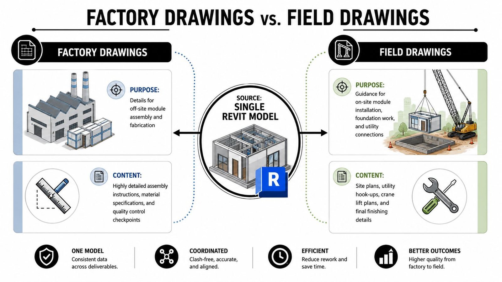
Managing Factory Drawings vs Field Drawings
One model can feed both the plant and the site. It should not treat them as the same audience.
Fabrication drawings are for people assembling panels or modules in the factory. Field drawings are for people setting, connecting, and finishing those components on site. If both outputs are squeezed through one sheet logic, one of those crews is going to work harder than they should.
What the plant needs
Factory drawings should read from module or panel datums, assembly sequence, and production checkpoints. They need clarity around part relationships, rough-in locations, recurring connection details, and QA hold points.
Plant-floor documentation usually gets worse when teams inherit traditional sheet sets built around architectural presentation. Those sets often over-prioritize building-grid logic and under-prioritize how the module is fabricated, inspected, and moved.
What the site crew needs
Field and site drawings answer a different set of questions. Foundation geometry, utility interfaces, crane set sequence, final seam conditions, and assembly between sections all belong here. These drawings need enough information for the GC, installer, and inspectors to understand what arrives complete from the plant and what gets finished in the field.
A useful test is simple. If a superintendent has to interpret plant assembly intent from permit sheets, the split was handled too late.
Teams that issue large drawing packages also benefit from making document structures easier to retrieve and sort. The same thinking behind making your content searchable and monetizable applies here in a practical sense. If sheets, details, revision notes, and module-specific outputs aren't indexed and named consistently, retrieval gets slower and errors creep in.
Factory drawings tell crews how to build the unit. Field drawings tell crews how to receive, set, connect, and close it.
Build that distinction into view templates, browser organization, annotation standards, and sheet sets from the start. Retrofitting it after active jobs are underway usually creates duplicate views, tagging inconsistencies, and revision confusion.
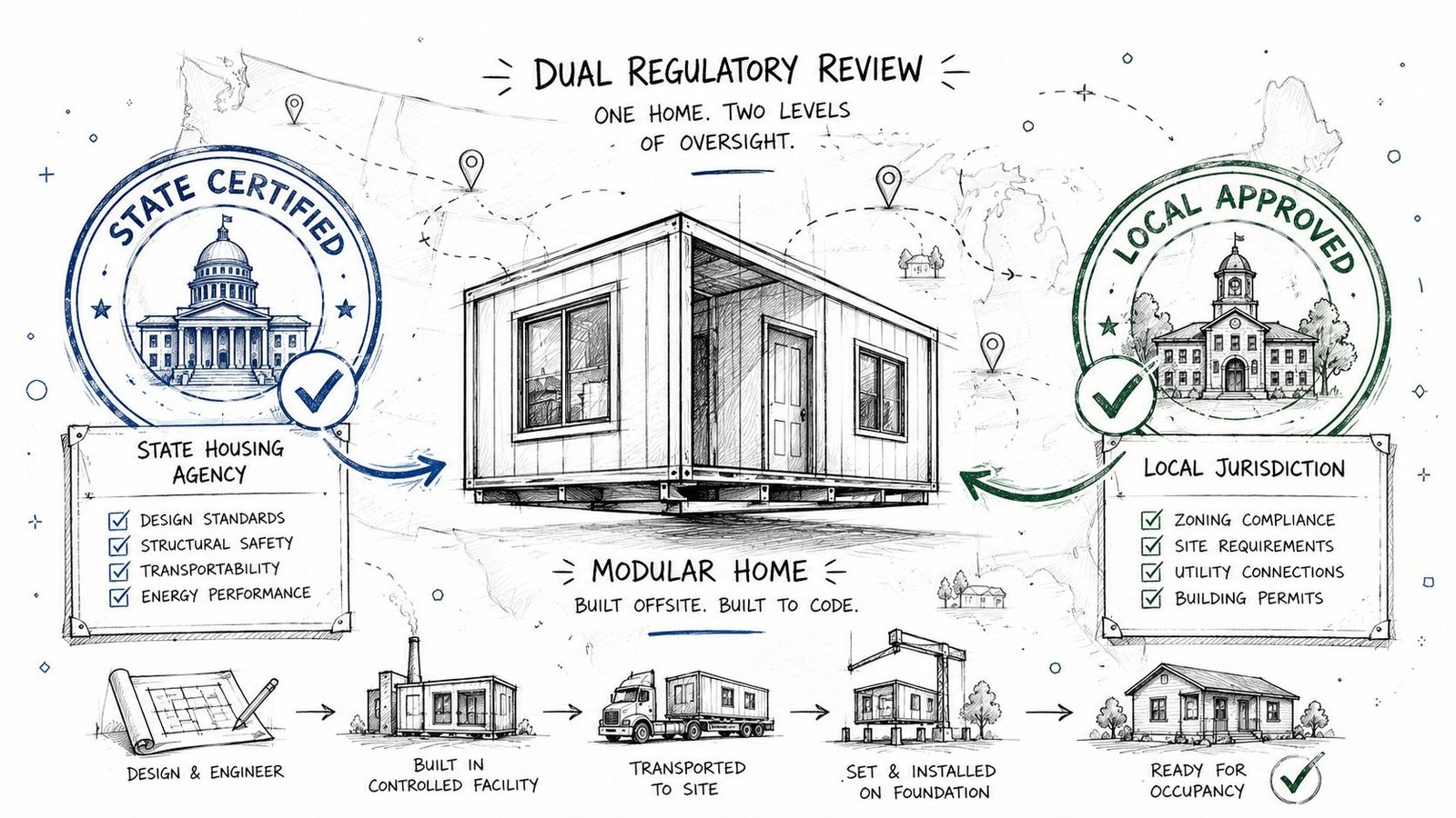
Navigating Code Review Across Multiple Jurisdictions
The regulatory side of modular housing punishes vague documentation. If the boundary between factory-certified scope and site-reviewed scope isn't clear, approvals slow down and responsibility gets blurred.
Most modular programs function with a split review path. The factory-built portion is reviewed through an accredited modular process, while the local authority having jurisdiction focuses on site-specific work such as foundation, utilities, and final assembly conditions. Your drawing set needs to make that split explicit.
Draw the review boundary clearly
The fastest way to create confusion is to let certified and field scope blur across sheets.
Use consistent notes, scope boundaries, and sheet organization so reviewers can immediately distinguish:
- Factory-certified components that are built and inspected under the modular program
- Site-specific work that remains under local review
- Interface details where factory and field responsibilities meet
That clarity helps permit prep internally too. Production, engineering, and permitting staff need the same boundary definition the reviewer sees.
Design for the patchwork, not around it
The code environment is still fragmented. HUD code requires modular and panelized construction to follow state and local standards, creating a patchwork across 50 states, and modular remains less than 5% of U.S. new construction as noted in Built America Magazine's discussion of modular housing barriers. For manufacturers shipping across state lines, that isn't a policy footnote. It changes how the set is organized, stamped, and reviewed.
Some plants make the mistake of building one “master” set and assuming state-specific adjustments can be added at the end. That usually creates friction because submission logic itself differs. Sheet order, note language, agency expectations, and approval markings may all need a predictable structure.
The stronger workflow is modular in the document sense too. Create a controlled base package, then layer state-specific compliance outputs without rewriting the whole set every time.
Front-Loading MEP Coordination for Panelized Construction
In site-built work, crews can often work around problems. In panelized and modular housing, that escape route gets narrow fast.
Once a panel is fabricated or a module is closed up, the rough-in is largely fixed. Chases, penetrations, device locations, and service paths can't depend on field improvisation. That's why factory-built housing BIM needs earlier coordination gates than a typical architectural project.
Resolve clashes before fabrication, not after release
The usual sequence in conventional work leaves some flexibility for trade adjustments. A modular plant doesn't have much use for that assumption. The model has to answer coordination problems while the work is still digital.
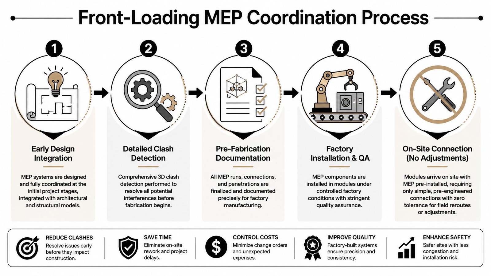
That means architectural, structural, and MEP teams need decision checkpoints tied to release status, not just design milestones. If one discipline is still “figuring it out” after framing or panel output begins, the workflow is already late.
What rigid coordination actually means
Rigid doesn't mean overcomplicated. It means specific.
- Penetrations are assigned and documented before fabrication release
- Rough-in zones are protected so structure and finishes don't inadvertently consume them
- Clash checks are tied to sign-off rather than treated as optional coordination hygiene
- Pod and utility interfaces are standardized wherever repeatable module types allow it
That last point matters a lot for high-repetition areas. Teams working through modular bathroom pod coordination usually discover that the pod itself isn't the hard part. The hard part is keeping the architectural shell, structural allowances, and MEP connection points aligned across every model variation.
If a field electrician would need to “make it work,” the model isn't ready for panel release.
QA proves its worth not as a final review ceremony, but as a disciplined check that rough-in logic, annotation, schedules, and issued details all agree before the work leaves the digital environment.
Detailing Tolerances and Connection Points
Factories can hold tighter control than field framing, but that advantage only matters if the connection details are documented clearly. Precision in fabrication doesn't help much when the joining conditions are left to site interpretation.
Marriage walls are the obvious example. When multi-section units come together on site, small ambiguity in alignment, fastening, seal continuity, or finish closure can create a chain of rework. The same goes for module-to-foundation interfaces and repeated panel-to-panel joints.
Where documentation has to be explicit
The details that usually need direct attention include:
- Marriage wall conditions and who completes each side of the assembly
- Set sequence drawings showing order of placement and access assumptions
- Connection hardware and seal locations tied to approved details
- Tolerance notes that define what the field can accept and what must be escalated
This is not the place for “contractor to verify” as a substitute for coordination.
A useful byproduct of factory precision is envelope performance. Modular homes are approximately 15% more energy efficient than site-built homes due to ultra-air-tight envelopes achieved through factory-controlled assembly, as described in this industry video on modular home efficiency. But that performance depends on continuity. If seam conditions, compressible seals, or closure details are loosely documented, the energy advantage gets undermined at the exact interfaces that matter most.
Field judgment still matters, but less than many teams think
Experienced set crews are valuable. They can solve real site problems. They should not be asked to invent critical connection intent.
When plants standardize connection details and sequence diagrams, the field spends less time interpreting and more time executing. That's what predictable delivery looks like in practice.
Managing Model Scale Across a Full Product Line
The test isn't whether one modular model works. It's whether ten active models, each with option sets and state-specific outputs, can be updated without breaking each other.
That's where many teams hit a second wall. They fix one product line, then lose control when the catalog expands. More unit types mean more linked content, more drawing outputs, more active revisions, and more chances for one change to ripple into unrelated work.
The system that keeps scale under control
At product-line level, the workflow has to act like a managed platform.
A stable setup usually includes a shared central library, linked model strategy, naming discipline, revision status control, and role-based ownership for who can change what. If every architect, drafter, or coordinator can edit production content directly, consistency won't last.
A practical governance model often separates decisions this way:
| Area | Best owner |
|---|---|
| Core unit logic | Product or standards lead |
| Library content updates | BIM manager or content manager |
| Project-specific placement | Delivery team |
| Release approval | Cross-functional production checkpoint |
That structure keeps local job pressure from subtly rewriting the standard product.
Why this is margin protection, not bureaucracy
The pushback usually sounds familiar. More standards, more locking, more checkpoints, more naming rules. It can feel heavy until the first broad design change lands across active jobs.
Then the value becomes obvious. Teams either update centrally and push approved changes with control, or they scramble through a stack of disconnected files hoping they didn't miss one detail, one schedule, or one rough-in note.
A scalable Revit workflow for modular housing manufacturers is less about modeling speed and more about controlled change.
That's the core mindset shift. This is not a bigger custom-home workflow. It's a manufacturing system with BIM at the center. Template discipline, CAD-to-BIM evolution, QA routines, permitting prep, and delivery pods all work better once the model behaves like a product backbone instead of a project container.
Conclusion From Project Model to Production System
The strongest modular teams don't use Revit as a drafting platform with better graphics. They use it as the operating layer of production.
That requires a different set of choices. Unit types need to be treated as managed product assets. Options should be parameter-driven where possible. Factory drawings and field drawings need separate logic from the start. Code review boundaries must be visible. MEP coordination has to happen before fabrication, not during installation. Connection details need to remove ambiguity, not leave room for interpretation.
When that system is in place, modular housing gets closer to the benefits that make it worth pursuing in the first place. Modular homes can save 10–25% in costs and cut construction time by nearly two months compared to stick-built homes, but those gains are often hindered by operational and workflow inefficiencies according to Urban Institute's analysis of modular construction and the housing shortage. In practice, that means the production model matters as much as the product itself.
This is why Revit for prefab manufacturers has to be approached as systems design. Not just file setup. Not just family creation. Systems design.
If your current workflow still depends on copied project files, late coordination, and manual drawing cleanup, you don't need a few better standards. You need a production framework that can hold repeatability under pressure.
That shift takes discipline, but it pays back in predictability, cleaner releases, fewer RFIs, and better control of margin across the full product line.
If you're reworking your production environment and need a clearer benchmark, BIM Heroes offers support built around architectural production and dedicated delivery resources. If a soft starting point is more useful, ask for a production model checklist, a library audit framework, or a review of your current modular home production drawings. That kind of conversation is usually enough to show where the workflow is behaving like a project, and where it's ready to behave like a scalable system.
Category: BIM Technology & Workflows