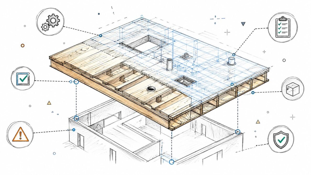
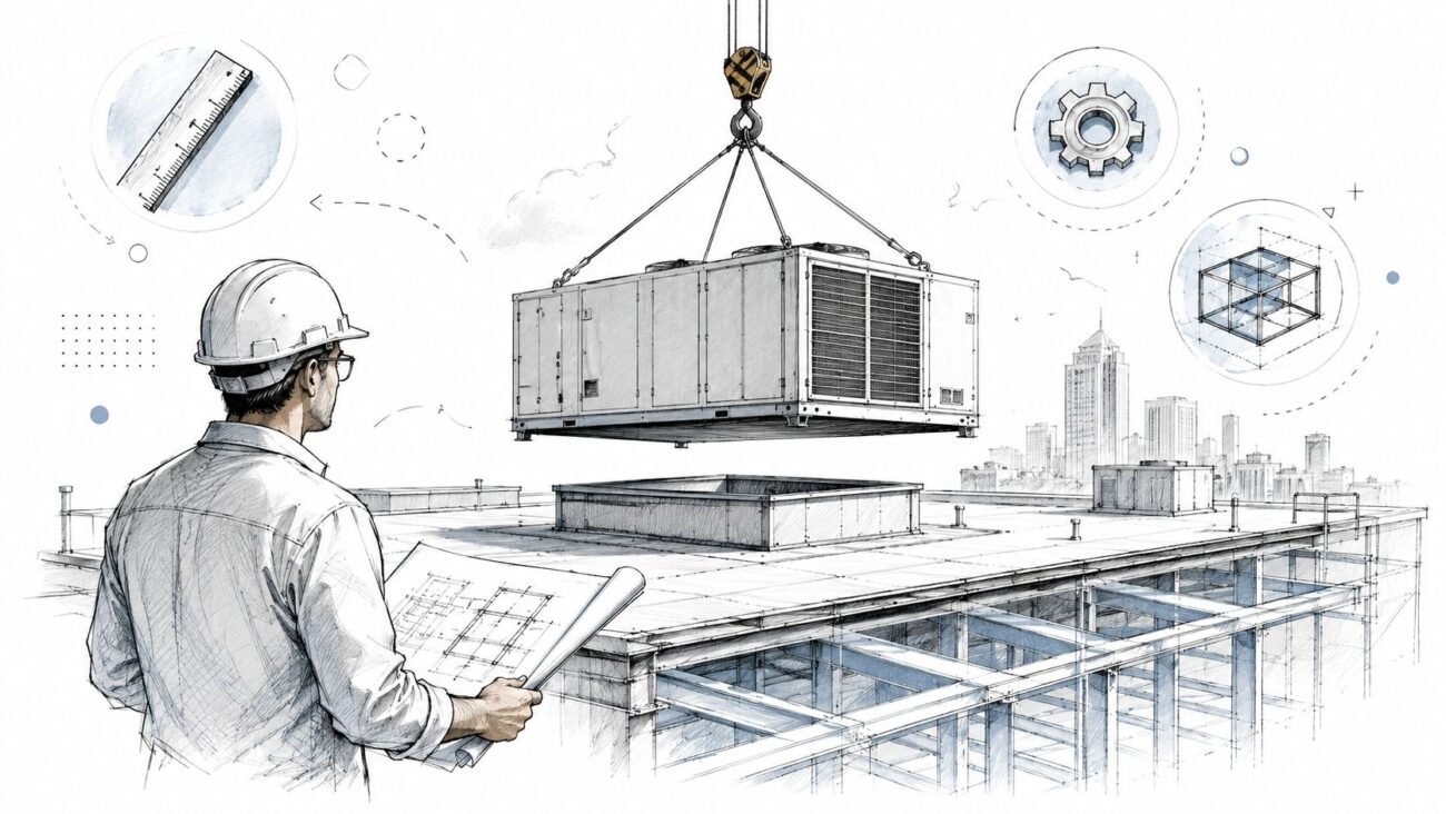
The bathroom pods arrived on site, and three things didn't fit. The rough-in locations followed the pod manufacturer's standard layout, not the coordinated model. The MEP connections at the chase wall missed what the plumbing contractor had already roughed in. The pod height clearance hit a structural beam overhead. None of that was hidden. All three conflicts were visible in the model before release.
That failure usually comes from one bad assumption. Teams treat a manufactured bathroom pod like a site-built bathroom with better packaging. It isn't. Once fabrication is released, the geometry, interfaces, and connection points are effectively locked.
That's why modular bathroom pods BIM coordination has to run as a production-gate process, not a late design check. And with the category already operating at scale, including a market estimate of USD 5.9 billion in 2024 with a projection to USD 9.3 billion by 2030 at a 6.8% CAGR according to this prefabricated bathroom pods market report summary, the workflow can't be handled casually. If your team is moving deeper into Design for Manufacture and Assembly, this checklist is the discipline that protects schedule, prevents RFIs, and keeps margin from leaking out in the field.
Introduction
On a live multifamily job, pod coordination failures don't show up as abstract BIM issues. They show up as rework, stalled floors, and calls from the site asking who approved fabrication.
The pattern is familiar. Architectural teams assume the unit bathroom matches the design intent model. Plumbing rough-ins follow one issued layout. The manufacturer develops a pod model to its own standard. Structural framing shifts slightly at one level. Nobody stops the release long enough to verify the interfaces against the federated model floor by floor.
That's the mistake. Bathroom pod multifamily construction succeeds when the pod is treated like a delivered product with zero tolerance for improvisation after release. The release gate has to be explicit, signed off, and tied to model checks that answer one question: will this exact pod fit, connect, clear, and finish correctly at the installed location?
Why Pod Coordination Demands a New Workflow
A pod model that is released one week too early can lock in months of avoidable cost. On a multifamily project, the site team can usually recover from a shifted branch line or a missed wall backing detail. A manufactured bathroom pod changes that equation because fabrication starts before the building is fully assembled, and the pod arrives as a finished component with fixed interfaces.
That changes BIM from a coordination exercise into a production gate.
In a conventional in-situ bathroom, trade coordination still allows some field adjustment. With pods, the tolerance for late decisions collapses. The BIM team is no longer checking whether the layout is generally coordinated. The team is confirming whether this exact unitized assembly can be fabricated, delivered, set, connected, and closed without cutting the pod or rebuilding adjacent work. Teams already familiar with off-site construction coordination workflows recognize the pattern. The release point matters more than the model appearance.
What changes at fabrication release
Fabrication release is the line that matters. Before release, the model can still be corrected. After release, every unresolved interface becomes a cost item.
These items usually hard-freeze first:
- MEP connection zones at the chase wall and slab interface
- Structural support geometry including bearing points, embeds, and framing assumptions
- Finished floor and ceiling relationships driven by exact level data
- Perimeter finish conditions where the pod meets corridor walls, demising walls, and site-built assemblies
The trade-off is straightforward. Parallel manufacturing can save time on site, but only if the coordination model is treated like a fabrication record. If a mismatch shows up after release, the team pays in two places. Design has to be revised, and the field loses installation flow while crews wait for an approved fix.
My rule on pod jobs is simple. If the site fix involves cutting, reframing, re-roughing, patching, or shifting penetrations, the issue should have stopped release.
Why the manufacturer's model cannot be accepted at face value
The manufacturer's model is built to support fabrication. Your coordination model is built to protect installation. Those are related goals, but they are not the same deliverable.
I see the same problems repeatedly. File origins do not match the project coordinate system. Reference planes do not align with structural grids. Connectors are present, but they reflect shop logic instead of building connection logic. Shared parameters are incomplete, and level offsets are baked into geometry instead of exposed for checking. A clean-looking linked file can still be wrong in every place that matters during install.
For a prefab bathroom pod Revit workflow, the BIM review has to verify five things before the model is treated as release-ready:
- Pod geometry matches the approved manufactured envelope
- Connector locations and sizes match the building-side services
- Level and offset data match slab, finish floor, and ceiling conditions
- Penetration locations work with the structural model and approved openings
- Installation assumptions match the actual access, lifting, and sequencing plan
Until that review is complete, the manufacturer file is only a reference object. It is not a coordinated production model.
Assembling Your Pre-Coordination Data Package
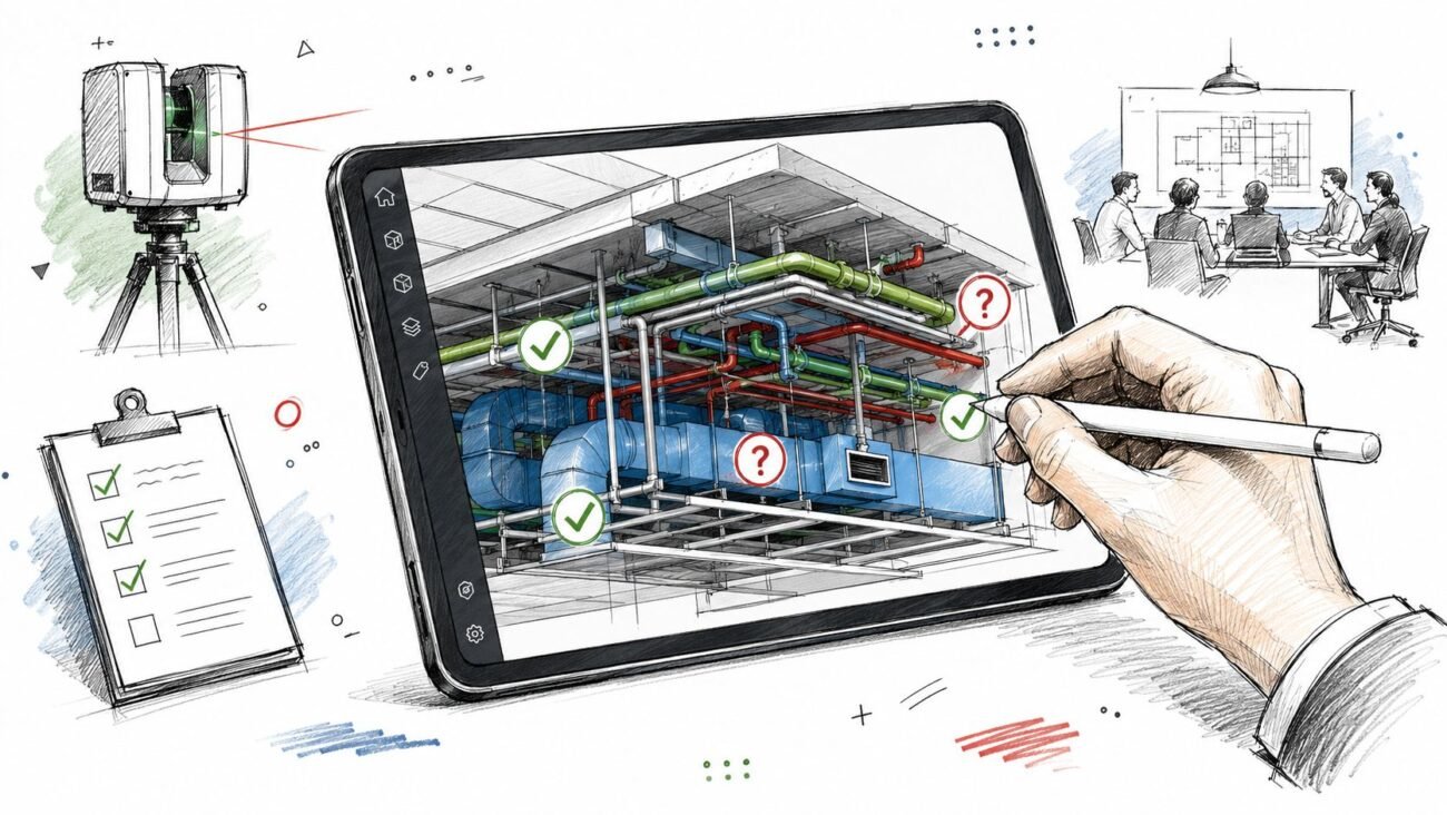
Before clash detection, before Navisworks viewpoints, before issue logs, the team needs a clean starting package. If even one input is still unstable, pod coordination turns into model theater.
The first required item is the manufacturer's actual pod model. That means the Revit family or IFC file from the pod supplier, not a generic bathroom group, not a design placeholder, and not a “close enough” family built during schematic design. The model has to contain accurate external dimensions, MEP connection points, connection sizes, floor penetration locations, and ceiling interface geometry.
If the manufacturer only provides 2D shops, build the coordination model first. Don't proceed with assumptions. Teams working in off-site construction workflows already know this, but it still gets skipped when deadlines tighten.
The minimum input set
You need three stable inputs before coordination starts:
Manufacturer model data
Confirm overall pod geometry, service connections, access side, lifting assumptions, and any integrated ceiling or floor build-up that affects fit.Structural model and drawings
Beam locations, slab edges, depressed slabs, steps, openings, and level data must already be loaded and current.MEP chase and riser layout
If the chase width, riser positions, or service routing are still moving, stop. Pod coordination depends on those paths being fixed enough to test against.
One input that gets missed too often
Weight and support data must be in hand before the pod is treated as installable. The pod isn't just a box in a room. It's a lifted manufactured unit that has to be transported, craned, landed, and supported without overstressing structure or access paths.
That matters because modular bathroom pods are commonly about 5 to 8 ft wide, 7 to 12 ft long, and 8 to 9 ft high, with finished weights often in the 3,000 to 8,000 lb range according to this modular bathroom pod guide. Those dimensions and weights drive crane planning, floor loading checks, and access verification. If your model doesn't reflect the actual pod envelope, every downstream clearance check is suspect.
Verifying Dimensional and Structural Interfaces
This is the first hard gate. Don't start detailed modular pod MEP coordination until the pod physically fits the building and the structure can support the installation logic.
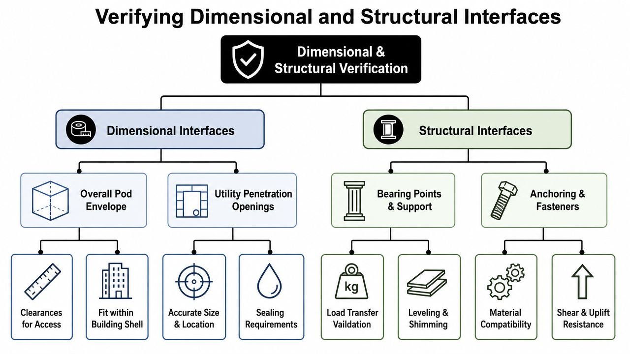
Check the plan footprint on every floor
Overlay the pod model on the architectural plan and verify the actual footprint against walls, shafts, doors, and circulation. Use the manufacturer model as the governing geometry. Don't rely on the architectural room box or a repeating unit assumption.
Review these items floor by floor:
- Wall clearances so the pod can be set without forcing framing changes
- Door swing and approach so the unit entry and bathroom door relationship still works
- Corridor and access path width after installation logistics are considered
- Tolerance zones where framing variation could erase your install margin
A typical floor is not enough if the plan shifts at corners, amenities, transfer levels, or accessible units.
Verify height against slab and beam conditions
Integrated pods with fixed ceilings are unforgiving. If your building has varied beam depths, transfer conditions, or stepped slabs, the pod height has to be checked at each unique level.
Look at:
| Interface | What to verify |
|---|---|
| Pod top to slab underside | Confirm install clearance and permanent fit |
| Pod top to beam soffit | Check local conflicts at beam crossings |
| Internal finished ceiling | Verify the usable inside height remains as intended |
| Tolerance allowance | Leave room for real-world install variation, not idealized geometry |
A pod that fits on the typical floor can still fail at the podium, transfer level, or roof-supported level. Those are the floors that create the expensive surprise.
Overlay penetrations with structural review
The pod's drain and supply penetrations need to be laid directly over the structural slab model. This isn't a quick visual pass. It needs a reviewed overlay with the structural engineer involved.
Focus on three failure points:
- PT tendon or reinforcing conflicts
- Slab depressions, steps, or edge thickening
- Penetrations landing too close to beams, embeds, or sleeves
If the pod penetrations require slab changes, that issue must be resolved before fabrication release. Otherwise the project creates a false promise in the model that concrete can't support in the field.
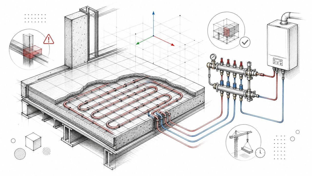
Aligning Critical MEP Connection Points
A pod can clear every dimensional check and still fail on install day because one drain is 25 mm high, a valve lands behind framing, or the conduit enters from the wrong face. Once fabrication starts, those are not field adjustments. They are cost events.
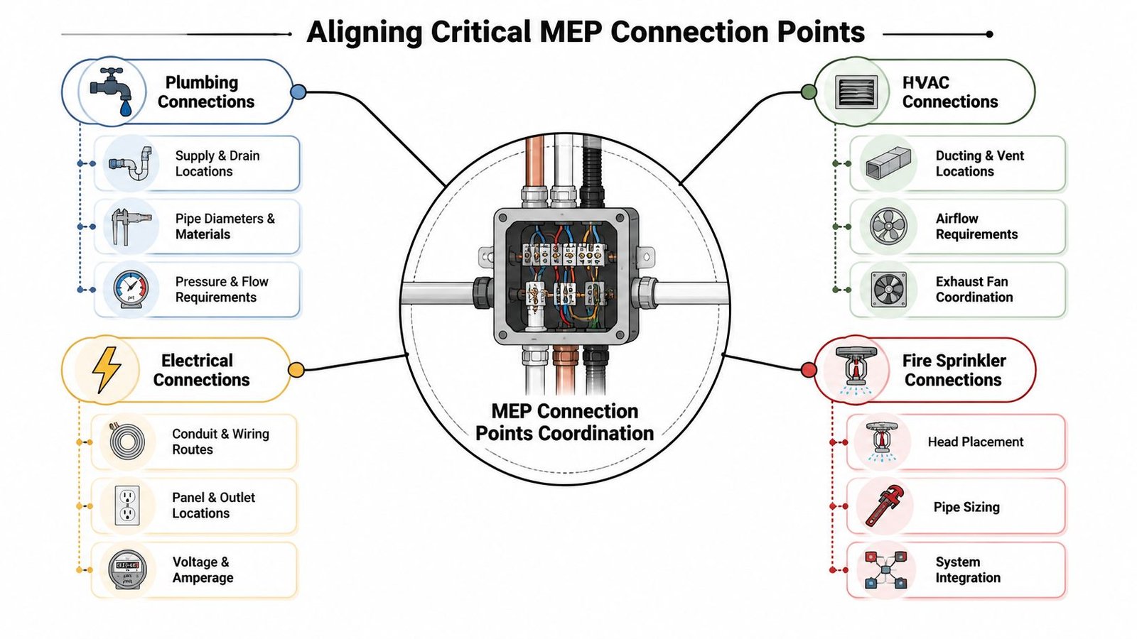
Define one approved interface zone
The BIM model needs one fixed service interface for each pod type, and that zone needs to be visible in plan, section, and coordinated 3D views. Include hot water, cold water, waste, vent, power, and exhaust where applicable. If the project uses floor buildup or screed to absorb service routing and tolerance, carry that allowance consistently in the host building model, as noted earlier.
Teams get into trouble when the pod manufacturer, plumbing engineer, and site crew are each working from a different idea of where “the connection area” starts and stops. Lock the zone down early, then publish it in the same level of detail you would expect in coordinated prefab shop drawing examples.
Check each connection like a release item
Treat every MEP connection as a fabrication gate. The question is not whether it looks close in a composite view. The question is whether the building-side service can connect to the pod exactly as manufactured.
Drain connection drives the review. Confirm outlet location, invert elevation, pipe size, and required slope back to the riser. If the run only works by flattening slope or shifting the trap arm in the field, the model is not coordinated.
Hot and cold water need exact rough-in alignment. Verify connection type, centerline location, elevation, insulation allowance, and valve access. A supply point that is horizontally aligned but vertically wrong still fails installation.
Vent connection has to match the actual vent strategy for that stack. Review location, size, offset risk, and how the vent leaves the pod and enters the chase. A vent that only works in the mirrored unit, or only works before a unit plan revision, is not approved.
Electrical connection needs more than a receptacle or junction box symbol. Confirm voltage, amperage, connection point, containment, and conduit entry direction. Entry direction affects install sequence, access, and finish protection.
Remove interpretation from the handoff
Field crews should not be deciding which side of the pod receives power or how far the waste stub can drift. That decision belongs in coordination, before procurement release.
The recurring failure points are predictable:
- Using 2D backgrounds after 3D manufacturer geometry is available
- Approving “typical” connection locations without checking mirrored units, end units, and accessible layouts
- Letting plumbing rough-in proceed before pod connection points are frozen
- Trusting generic Revit connectors that have not been checked against the manufacturer's install intent
On multifamily work, profit margins are either safeguarded or diminished. If connection points are fixed, tagged, and signed off before fabrication, installation becomes repeatable. If they are left open to interpretation, the corridor fills up with workarounds, RFIs, and patching.
Modeling the MEP Chase and Riser Stack
The chase serving a vertical pod stack is usually the most unforgiving zone in the building. If it's under-modeled, the project won't feel the error immediately. It will feel it when sleeves are wrong, framing is too tight, or risers start offsetting floor to floor.
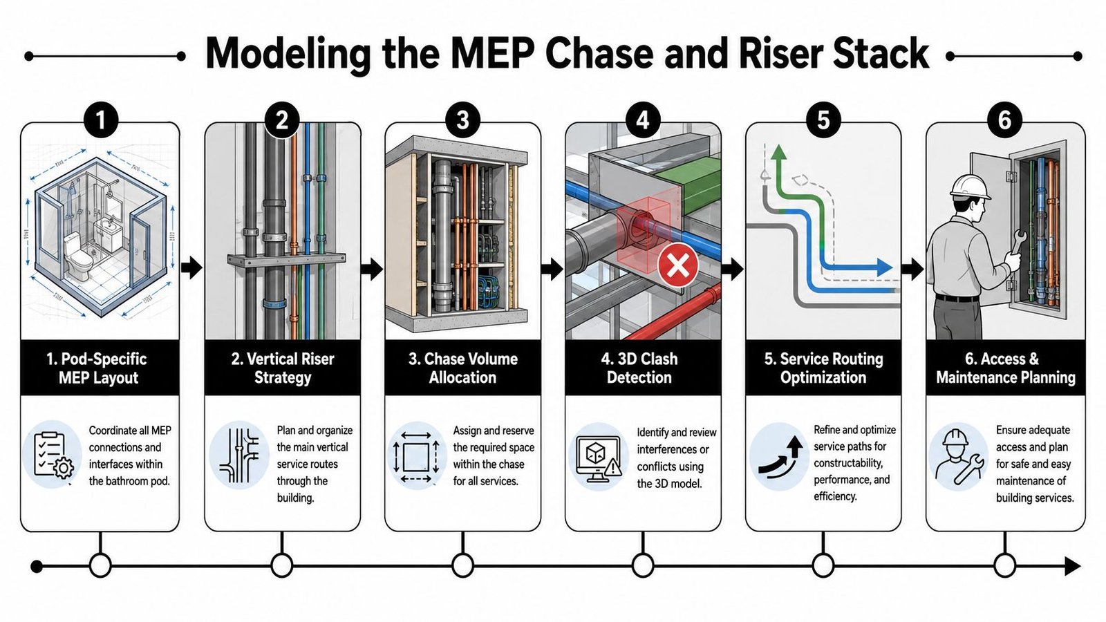
Treat the chase as a modeled system
Don't model just the pod connections and call the chase coordinated. Model the full vertical content, including pipes, vents, conduit, and exhaust path if applicable. Then test framed chase dimensions against actual service density and installation access.
A good chase review answers these questions:
- Can every service fit without forced offsets?
- Can sleeves be issued before slab work?
- Can the risers stay vertically aligned through the stack?
- Can someone still access the system for installation and maintenance?
If the answer to any of those is vague, the chase isn't coordinated.
Push sleeve data out early
Wherever risers penetrate structure, extract those openings directly from the coordinated model and issue them early. That handoff needs to reach both the structural engineer and the contractor before slab construction.
A lot of pod projects promise schedule gains but lose them in unresolved penetrations. In a published modular case study, offsite components such as bathroom pods helped cut 3 months from the schedule of a 100-bed hospital project with no increase in costs, according to the NIBS modular bathroom pods case study. Those gains only hold when field interfaces are settled before installation work starts. If your sleeve package is weak, you give the schedule back.
Teams that already produce disciplined shop drawing examples for coordination-driven delivery tend to handle this better because they understand that every penetrated slab is a release item, not just a drawing note.
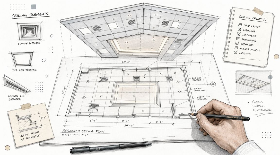
Integrating with the Architectural Model
Architectural coordination is where pod jobs often get undermined by “small” details. The pod itself may be fully fabricated and technically correct, but the installed result still fails if the perimeter conditions weren't modeled and detailed.
Resolve thresholds and floor transitions
The pod floor finish is usually set by the manufacturer. That means the transition to corridor or adjacent room flooring has to be designed, not improvised. If the pod floor sits proud of the adjoining finish, accessibility and detailing both become live issues.
Review the condition in section and in plan. Don't let the threshold remain a drafting placeholder while fabrication proceeds.
Protect the acoustic assembly
Pod walls are manufactured assemblies. If the project expects a certain acoustic performance, the interfaces at top, bottom, and sides need architectural details that preserve it. Gaps at the slab or ceiling line can't be left for a sealant decision in the field.
Use details that answer these questions:
- What closes the joint at the pod head?
- How is the perimeter sealed without breaking tolerance needs?
- What assembly completes the side wall finish?
Acoustic intent fails at interfaces, not in product literature.
Detail the finish perimeter
The pod perimeter has to meet site-built drywall, trim, ceilings, and sometimes millwork. If that joint isn't shown clearly in the coordinated model and drawings, finishing trades will invent the condition.
That usually leads to one of two bad outcomes. Either the finish looks patched, or someone cuts into a manufactured edge that shouldn't have been touched. Both are avoidable if the perimeter joint is modeled as an architectural interface instead of an installation afterthought.
The Final Coordination Sign-Off Checklist
A pod gets released on Friday. By Monday, the site team realizes the waste outlet misses the planned riser position, the ceiling framing clashes with the top of the unit, and the electrical entry is coming from the wrong side. At that point, coordination is over. The project is paying for rework, delay, or both.
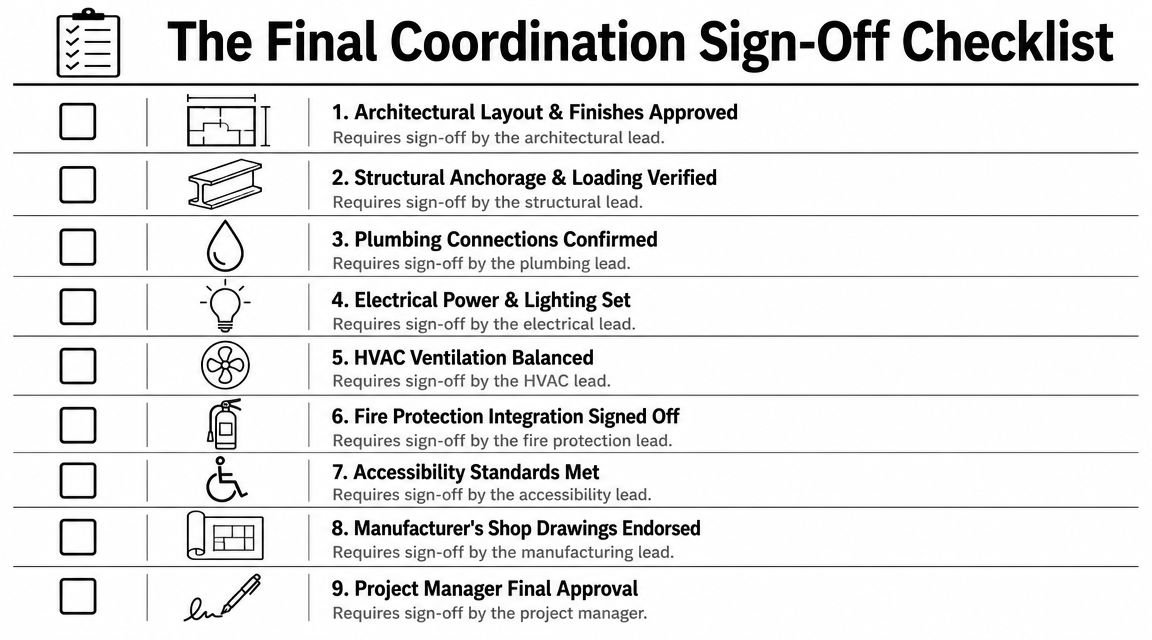
Fabrication release is a production gate. Treat it that way. The pod is a manufactured component with no tolerance for late interpretation, field adjustment, or half-resolved coordination comments.
Every item below needs discipline-lead sign-off before release, with the current model and issued drawings matching each other.
Release gate checklist
Pod footprint approved on every floor
The manufacturer model has been checked against the architectural plan at each pod location, including offset stacks, mirrored layouts, corner conditions, and non-typical levels.Ceiling and overhead clearance verified
Slab edges, beam drops, soffits, and overhead framing have been checked against the actual pod height and installation path on every affected floor.Structural penetrations cleared
Drain, vent, water, and electrical penetrations have been reviewed with the structural model and structural engineer input. No opening conflicts remain at slabs, beams, walls, or embeds.Drain elevation and slope confirmed
Plumbing has verified outlet invert, horizontal run length, and achievable slope back to the building waste line without changing the pod outlet position.Hot and cold supply interfaces verified
Connection size, type, centerline, valve requirement, and rough-in zone match between the pod shop model and the building plumbing model.Vent connection approved
The vent outlet location aligns with the final riser layout, and the connection can be built without forcing offsets that were not modeled.Electrical connection signed off
Connection point, voltage, amperage, circuiting, disconnect requirement, and conduit entry direction match the coordinated electrical model and issued documents.Chase volume validated
The full riser stack has been modeled inside the available chase volume, including insulation, supports, firestopping space, and access constraints where required.Penetration schedule issued
Sleeve and opening data have been taken from the coordinated model and issued in time for structural deck, slab, and wall work.Vertical stack alignment checked
Pod service points align floor to floor, and every shifted unit or transfer condition has been reviewed as its own interface, not assumed from the typical stack.Installation sequence reviewed
The team has confirmed crane, hoist, corridor, and set-clearance requirements so the pod can be delivered and installed without cutting surrounding work.Authority and code requirements closed
Required backing, clearances, access zones, and rated assembly conditions that affect the pod interface have been incorporated into the coordinated model and issued details.Open clashes and RFIs closed
No fabrication-impacting clash, coordination comment, or unresolved RFI is sitting open under a note to revisit later.
What sign-off should actually mean
Sign-off means one thing. The pod can be fabricated and installed from the issued package without field redesign.
“Reviewed” is not enough. Each discipline lead needs to confirm that geometry, connection points, tolerances, and installation assumptions are resolved in the model that governs fabrication. If the plumbing lead is still waiting on a riser decision, or architecture is still carrying a generic wall interface, release is premature.
That delay costs less than a bad release. A missed interface in a site-built bathroom can sometimes be absorbed in the field. A missed interface in a prefabricated pod usually turns into scrap, resequencing, or a stalled install crew.
Multifamily pod work stays profitable when BIM sign-off is treated as production control. If your team needs support tightening modular bathroom pods BIM coordination or cleaning up chase and connection risk before fabrication, contact BIM Heroes on our MEP coordination support page.