


A sprinkler main that appears clean in a standalone fire protection model can become an expensive problem once it meets the building. Ductwork occupies the corridor zone, beams limit penetration locations, ceiling grids control head placement, and fire alarm devices compete for visible, serviceable positions. If those relationships aren't resolved early, the project pays for the same decision repeatedly through RFIs, redraws, field changes, and inspection comments.
That's why fire protection design mistakes are production failures as much as code failures. A technically correct system can still be difficult to install, impossible to inspect efficiently, or poorly documented for maintenance. The practical solution is to coordinate sprinkler, alarm, structure, architecture, and other MEP systems in a federated model before the drawings look finished.
The Hidden Cost of Fire Protection Design Mistakes
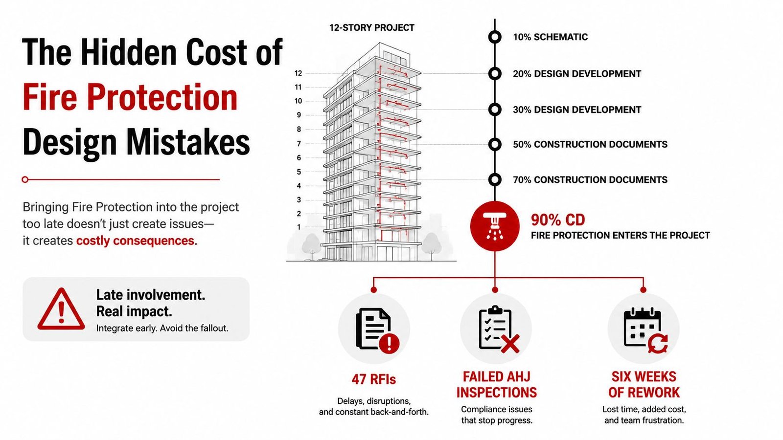
A familiar project pattern is a 12-story mixed-use building where fire protection enters coordination at 90% construction documents. By then, HVAC routing, structural framing, ceiling layouts, and architectural details are already treated as fixed. The sprinkler designer receives a nearly complete background, places mains and branch lines into the remaining space, and discovers that the available space exists only on paper.
The result is a chain of coordination failures: 47 RFIs, failed AHJ inspections, and six weeks of rework across mechanical and structural disciplines. Those figures describe the scenario, not a published industry statistic, but the pattern is recognizable to anyone reviewing late-stage MEP models. A single unresolved crossing can force changes to supports, sleeves, ceilings, access panels, electrical devices, and architectural finishes.
Fire protection isn't a standalone trade. The system touches ductwork routing, structural penetrations, ceiling plenums, fire-rated assemblies, alarm circuits, egress planning, and access for inspection and maintenance. NFPA reports that local fire departments responded to an estimated average of 52,948 structure fires per year from 2017 through 2021 where sprinklers were present, representing 11 percent of all structure fires. NFPA's US sprinkler experience report provides the broader context for why system reliability and installation quality matter.
The costly mistakes tend to repeat:
- Late integration, which creates avoidable clashes.
- Poor sprinkler routing and head spacing, which compromises coverage and ceiling coordination.
- Missed AHJ requirements, which turns a permit or inspection into a redesign cycle.
- Inadequate hydraulic calculations, which exposes the project to water-supply and acceptance problems.
- Overlooked passive fire protection, especially penetrations and firestopping interfaces.
The prevention framework is straightforward. Establish the design basis early, model the system against current architectural and engineering backgrounds, run focused clash checks, and issue documentation that a contractor and inspector can use.
Mistake 1 Integrating Fire Protection Too Late in the Design
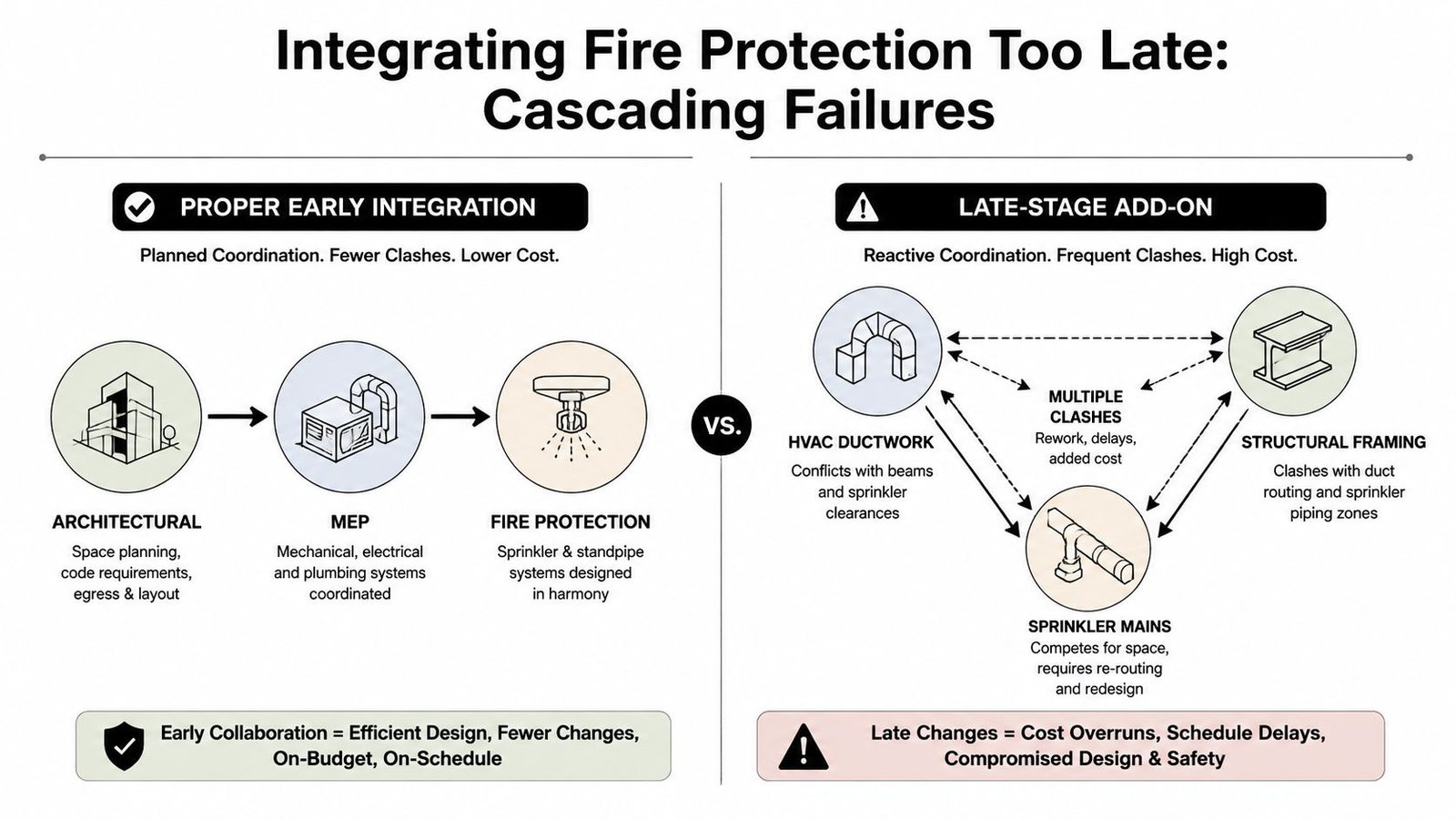
Late integration creates more than a few red clashes in Navisworks. It removes the design team's ability to make low-impact decisions.
Suppose a 4-inch sprinkler main reaches a corridor and conflicts with a 24-inch return air duct at a structural beam penetration. The model review happens after the beam, duct, ceiling, and architectural soffit are already coordinated. The team now has unattractive options: request a new beam penetration, lower the ceiling, reroute the duct, shift the sprinkler main, or introduce additional fittings that affect hydraulic performance.
Each option belongs to a different discipline, so the project manager inherits a coordination problem rather than a simple drafting correction. A late change can also affect hanger locations, access panels, insulation clearances, lighting, ceiling tiles, and fire-rated wall details.
Why the late model fails
IBC Section 903 establishes when automatic sprinkler protection is required based on occupancy and building conditions. The 2021 IBC rules are occupancy-specific. For example, Group A-1 triggers include a fire area exceeding 12,000 square feet or an occupant load exceeding 300, while Group A-2 triggers include a fire area exceeding 5,000 square feet or an occupant load exceeding 100. Group E triggers include a fire area exceeding 20,000 square feet, any level below grade, or two or more levels above grade. The IBC sprinkler trigger summary shows why code analysis must happen before routing decisions are locked.
NFPA 13 then governs installation constraints such as obstruction relationships, component arrangement, and system layout. If pipe lengths and fittings remain undefined until the end of documentation, the hydraulic model is also being developed too late.
The production-ready fix
Bring fire protection into the federated model by 30% design development, at minimum. At that checkpoint, teams should confirm:
- Primary routing zones: Reserve realistic space for mains, risers, branch lines, valves, and access.
- Structural interfaces: Identify sleeves, openings, beam conflicts, and prohibited penetrations before fabrication-level detailing.
- Ceiling coordination: Review sprinkler heads against reflected ceiling plans, lights, diffusers, access panels, and soffits.
- Hydraulic inputs: Use modeled routing, fittings, elevations, and pipe sizes as the basis for preliminary calculations.
- Decision ownership: Record who approves reroutes and which assumptions remain subject to AHJ review.
Practical rule: If the sprinkler model first appears when the project is nearly issued, coordination has already become construction work.
Mistake 2 Poor Sprinkler Routing and Head Spacing
A sprinkler layout can look evenly distributed and still fail a detailed review. Modelers often place heads by visual symmetry, then discover that walls, beams, ducts, light fixtures, bulkheads, or ceiling transitions interrupt the intended discharge pattern.
For standard spray sprinklers in light hazard occupancies, the plan notes identify 15-foot maximum spacing, 7.5-foot maximum distance from walls, and 4-inch minimum clearance below deflectors for smooth ceilings under the applicable NFPA 13 criteria. These values must be checked against the adopted edition, occupancy classification, ceiling condition, sprinkler listing, and AHJ interpretation. The relevant spacing table is NFPA 13 Table 8.11.2.1.1, not a generic drafting rule.
Where layout errors start
The most common failure is treating the ceiling plan as a finishing layer. A branch line is routed above a duct, heads are dropped into an apparently clear grid, and nobody checks whether the sprinkler discharge is blocked by a nearby obstruction. Another error is placing heads to satisfy a maximum distance while ignoring the actual usable area created by soffits, beams, partitions, or changes in ceiling elevation.
The problem becomes harder when branch lines occupy the only practical maintenance path. A route that works geometrically may leave valves, fittings, or concealed components inaccessible after ceilings are installed.
A better review sequence
Use Revit sprinkler placement tools with project rules and relevant spacing parameters visible during layout. Then run a dedicated clash review between sprinkler heads and ceiling-mounted elements, rather than relying only on a general MEP clash test.
A useful model review sequence is:
- Overlay the reflected ceiling plan with architectural grids, lighting, diffusers, speakers, and access panels.
- Check wall and obstruction distances against the project's adopted NFPA 13 basis.
- Review elevation relationships, especially where ducts, beams, clouds, and soffits change the ceiling condition.
- Test service access, including valves, drains, test connections, and concealed components.
- Color-code compliance status with Revit view filters so questionable heads stand out during coordination meetings.
For a focused reference on the standard, see NFPA 13 sprinkler design guidance. The useful deliverable isn't merely a model with heads placed. It's a coordinated layout with clear assumptions, visible exceptions, and an issue log that the design manager can close before submittal.
Mistake 3 Missing AHJ Requirements and NFPA 72 Compliance
Meeting the baseline code language doesn't guarantee approval. The Authority Having Jurisdiction may apply amendments, interpretation, submittal conventions, and inspection expectations that change how the design must be documented.
That gap appears late because teams often treat NFPA 13 and NFPA 72 as a checkbox. A permit package may satisfy the designer's reading of the standard but still receive comments about concealed-space coverage, notification appliance placement, smoke detection, zone boundaries, annunciation, or coordination between alarm devices and architectural features.
Build the AHJ matrix before drawing production
The project should have a written AHJ requirements matrix before the fire protection package reaches final documentation. It should identify the governing codes, adopted editions, local amendments, required submittal content, review contacts, inspection milestones, and unresolved interpretations.
The matrix should also connect requirements to model elements:
- Sprinkler zones: Confirm boundaries, riser relationships, control valves, and monitoring points.
- Alarm zones: Coordinate initiating devices, notification zones, interfaces, and panel documentation.
- Architectural spaces: Verify room names, occupancy assumptions, ceiling types, concealed areas, and egress relationships.
- Inspection records: Define what drawings, schedules, device identifiers, and revision notes must be available at closeout.
NFPA 72 compliance deserves its own review pass. Fire alarm devices shouldn't be placed only to fill open ceiling space. Their locations need to remain coordinated with room use, ceilings, obstructions, access, notification coverage, and the final architectural plan.
Treat compliance as a live checkpoint
Before the first formal submittal, compare the model and drawings against the matrix. After every significant architectural or MEP revision, repeat the affected checks. This is especially important when a ceiling change shifts both sprinkler heads and notification appliances, or when a partition revision changes room classification and device coverage.
Use fire alarm system design coordination resources alongside the project's adopted code documents. The internal workflow matters because a model can be geometrically coordinated while still being administratively incomplete.
AHJ checkpoint: Record the interpretation, the responsible reviewer, and the drawing or model location that proves compliance. Verbal assumptions disappear when the project changes hands.
A failed plan review costs more than the correction itself. It can delay permit release, compress procurement, force construction resequencing, and make the contractor carry uncertainty into installation. Early documentation turns local requirements into production controls instead of late surprises.
Mistake 4 Inadequate Hydraulic Calculations and Water Supply
Hydraulic calculations shouldn't begin after the pipe layout is considered complete. They should influence the layout from the point at which the design team establishes the hazard, design area, water source, and system arrangement.
Rule-of-thumb pipe sizing creates a particularly dangerous illusion. The pipes appear plausible in plan, but the most remote sprinkler may not receive the required flow and pressure once elevation, friction loss, fittings, backflow devices, valves, and available supply are included. A fire pump selected from an assumed demand can also fail to match the actual system curve.
Connect the calculation to the model
NFPA 13 water-supply duration depends on hazard classification, not one universal value. NFPA guidance identifies at least 30 minutes for Light Hazard, 60 to 90 minutes for Ordinary Hazard, 90 to 120 minutes for Extra Hazard, and a minimum of 60 minutes for exposure-protection sprinkler systems. NFPA's water-supply discussion explains why the duration must follow the applicable system basis.
NFPA 557 also provides a risk-based methodology for determining fire load and fire load density, which can form the basis of structural fire protection design. NFPA 557's standard development information is relevant when the structural fire strategy uses a quantified design fire rather than a purely prescriptive assumption.
| Failure Mode | Root Cause | Resolution Stage |
|---|---|---|
| Remote area cannot meet demand | Pipe sizes or routing were assumed before calculation | Schematic design |
| Water duration is unsuitable | Hazard classification and supply basis were not documented | Basis of design |
| Pump selection does not match demand | Pump data was selected from an unverified estimate | Design development |
| Calculation changes after coordination | Modeled lengths, fittings, or elevations were incomplete | Before permit issue |
Run preliminary calculations using available water-supply data, then coordinate with civil teams on fire-flow test information and incoming service constraints. In Revit, keep pipe sizes, system classifications, elevations, and fitting data consistent with the calculation model. The model doesn't replace the engineer's hydraulic software, but it should provide traceable geometry rather than disconnected drafting assumptions.
For adjacent domestic and building-service coordination, plumbing design production support can help keep shared risers, sleeves, plant spaces, and service zones aligned. The resolution is predictable when the calculation and model evolve together. It becomes expensive when the calculation exposes a routing decision after ceilings, structure, and equipment selections are already fixed.
Mistake 5 Overlooking Passive Fire Protection and Firestopping
Active systems receive the visible coordination attention because sprinkler heads, mains, alarms, and devices are easy to display in a model. Passive fire protection is less visible, but penetrations through rated walls and floors often create the inspection problem that stops closeout.
A pipe, duct, cable tray, or conduit can pass through a rated assembly without anyone clearly recording the approved protection system. Field crews then select a convenient firestop product, discover that the tested assembly doesn't match the opening, or leave the decision for inspection. Plastic piping may require a listed collar or wrap, ducts may require a rated penetration treatment, and structural steel may require the specified spray-applied fireproofing thickness.
Make every opening accountable
IBC materials define a fire-resistance rating as the period during which an element, component, or assembly maintains the ability to confine fire, perform its structural function, or both. ICC materials state that ratings commonly range from one-half hour to four hours. ICC's fire-resistance-rated construction presentation provides the code framework.
IBC Chapter 7 also distinguishes how ratings are established. Building elements use tests such as ASTM E119 or UL 263, while penetrations and fire-resistive joint systems are addressed under Sections 714 and 715. The FCIA code presentation summarizes those testing pathways.
The model should therefore capture more than the pipe centerline. Add penetration locations, rated assembly references, opening sizes, trade ownership, firestop system references, and installation status. Where the approved design uses UL or FM Global references, associate the applicable system with the penetration record rather than leaving the contractor to infer it from a general note.
Close the design to inspection loop
A practical Revit workflow includes:
- Penetration families: Place coordinated openings with host assembly and service data.
- Firestop parameters: Record the approved system, collar or wrap requirement, and responsible trade.
- Schedules: Generate penetration and firestop schedules directly from the model.
- Clash rules: Flag services crossing rated assemblies without a corresponding protection record.
- Closeout status: Track designed, approved, installed, inspected, and corrected conditions.
Industry guidance has also highlighted the need to standardize device naming, submittal templates, complete drawing packages, and alignment between design outputs and inspection workflows. That production discipline is valuable because a technically sound design can still generate closeout delays if nobody can prove what was installed or inspected.
How to Prevent Fire Protection Mistakes with BIM Coordination
A reliable fire protection BIM workflow doesn't start with clash detection. It starts with a design basis that every discipline can understand. Confirm occupancy, protection level, hazard classification, adopted codes, AHJ requirements, water supply assumptions, fire load scenario where applicable, and the intended deliverables before modeling production begins.
NFPA 1 requires buildings or portions assigned to Protection Levels 1 through 5 to have an approved automatic sprinkler system complying with NFPA 13. NFPA's Protection Level material makes the early code decision important because it affects zoning, water demand, pipe routing, ceiling constraints, and coordination scope.
Use milestone-based reviews
A production team can embed the following checkpoints into its model review cycle:
- At 30% design development: Confirm riser locations, main routing zones, preliminary hazard assumptions, ceiling interfaces, structural openings, and the AHJ matrix.
- At 60% design development: Review branch-line routing, sprinkler spacing, obstruction relationships, alarm device coordination, hydraulic inputs, and service access.
- At 90% construction documents: Run the final federated clash review, confirm resolved issues, validate schedules, check rated penetrations, and cross-reference the permit package against the AHJ matrix.
- Before issue for construction: Confirm that model elements, drawings, calculations, tags, schedules, and revision notes describe the same system.
Run targeted checks, not only generic clashes
Navisworks and Revit can identify hard clashes, but fire protection coordination also needs rule-based and visual reviews. Check sprinkler heads against lights, diffusers, beams, ceiling changes, and soffits. Check mains against structure and ductwork. Review access around valves, drains, test connections, risers, and inspection points.
For larger projects, define clash rules by priority. A main crossing a beam or a sprinkler head blocked by a duct deserves a different escalation path from a minor clearance issue. Assign each issue to a discipline, record the decision, and verify the correction in the next federated model.
Deliver documentation that survives handoff
The final package should support permitting, installation, inspection, and closeout. That means coordinated plans, sections, details, schedules, calculation inputs, penetration records, and clear revision control. Teams that outsource production should also establish a template, naming convention, model exchange protocol, QA checklist, and acceptance criteria before work begins.
BIM Heroes provides MEP engineering documentation and coordination workflows that can include fire protection modeling once the sprinkler basis has been established. For retrofit work, point-cloud-to-BIM production can help teams document existing conditions before routing new fire protection systems, with deliverables coordinated for common project platforms and downstream review.
The outcome isn't fewer colored clash markers. It's predictable production, fewer RFIs, less cross-discipline rework, cleaner permit preparation, and a model that supports inspection readiness. That protects margin because the team resolves decisions while they're still design decisions, not after materials, ceilings, and labor are committed.
If your firm needs coordinated fire protection MEP production or a focused clash-check against structure, HVAC, architecture, and existing conditions, BIM Heroes can review your model requirements and deliver a practical coordination workflow. Send your scan data or project background through the team's free consultation request to discuss LOD recommendations and pricing within 24 hours.