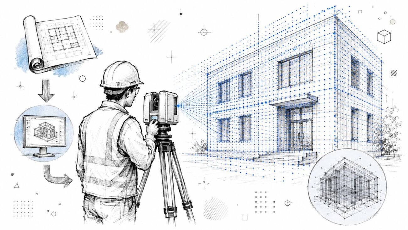
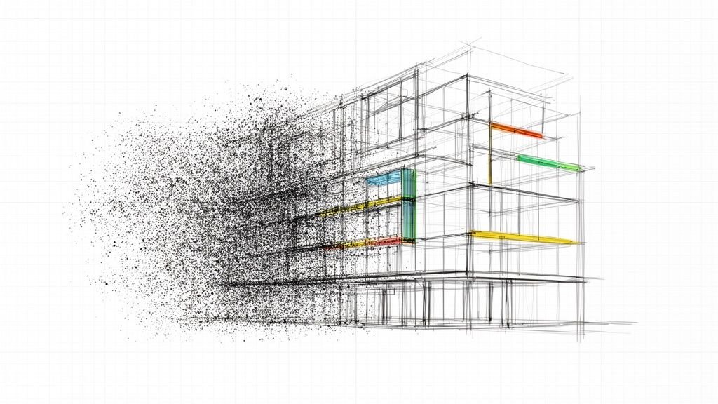
A scanning crew delivers a dense, full-color point cloud of a mechanical room. It looks excellent in the viewer, so the BIM team starts modeling pipe hangers, conduit, and equipment. Then the model refuses to align with the structural grid. Known control points reveal a dimensional problem, and the project team is left deciding whether to remodel, issue RFIs, or send the crew back to the field.
That situation exposes the central problem in 3D scanning quality control. A point cloud can be visually convincing while still being unreliable for measurement. Clean density, sharp textures, and attractive color deviation maps don't prove that the dataset is registered, controlled, or suitable for a specific BIM deliverable.
For firms that capture reality data but outsource production, the distinction matters even more. A structured scan-to-BIM workflow should make accuracy visible through repeatable checks, not vague assurances. BIM Heroes scan to BIM services include deviation analysis and a deviation report with every model, helping downstream teams review how modeled elements compare with the registered point cloud.
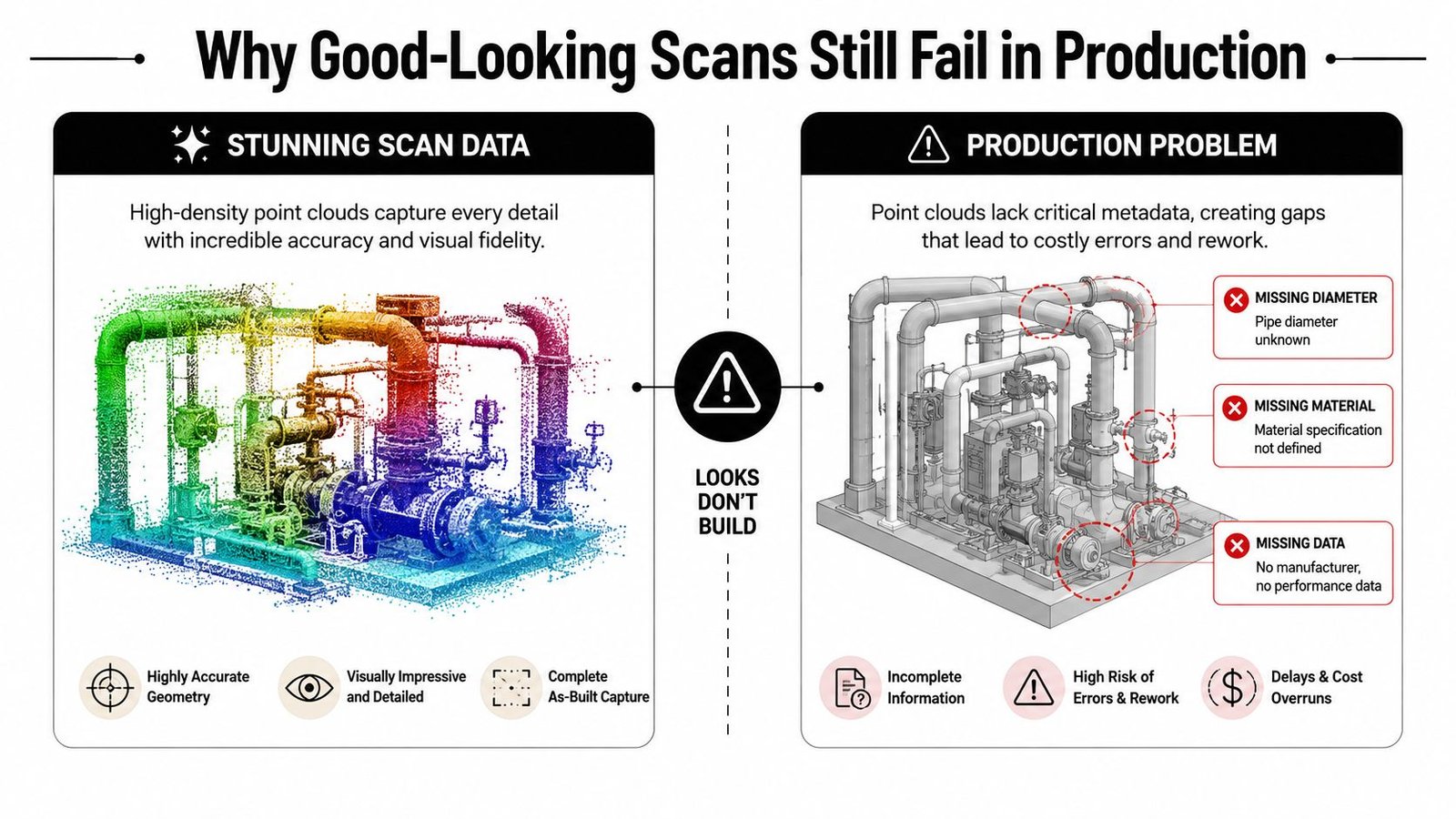
Why Good-Looking Scans Still Fail in Production
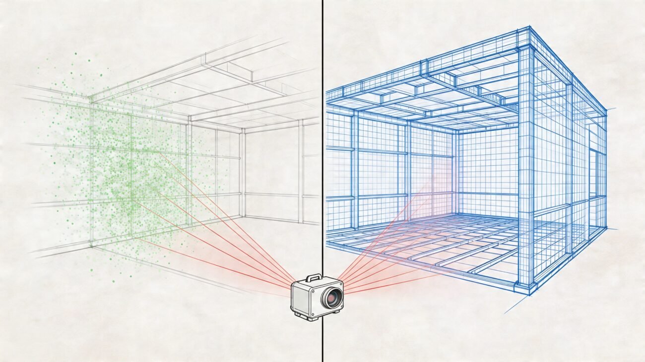
A mechanical-room scan can show crisp pipework, dense coverage, and convincing color while still failing against the structural grid. Registration drift may have accumulated across multiple setups, and without checks on control points, overlap, and residuals, the problem often appears only when modeling or coordination begins.
Visual quality and dimensional quality are different tests. Density and sharp textures confirm that surfaces were captured. They do not confirm that those surfaces occupy the correct coordinate positions. Color deviation maps can also mislead. They display relative differences or appearance, but cannot prove that the coordinate system, control network, and registration are sound.
Teams using point cloud scanning services should therefore define acceptance checks before production starts. A clean viewer image is evidence of presentation quality, not measurement quality.
The silent sources of dimensional error
Registration drift is a common cause. Weak geometry or limited overlap can force small alignment compromises between scan positions, allowing error to spread through the network. Uncalibrated sensors, reflective surfaces, moving equipment, and poorly integrated control points add further uncertainty.
The risk matters because scan data increasingly supports inspection and quality control. A market report estimates that the global 3D scanning market reached USD 4.28 billion in 2024, while the broader 3D metrology market reached USD 11.13 billion. It also identifies quality control and inspection as the largest application segment of the global 3D scanner market in 2024, with North America accounting for 37% of market revenue. The market report connects that inspection focus with the practical effect of millimeter-scale scan errors.
Production rule: Never approve a point cloud because it looks clean in the viewer. Approve it because it passes documented checks against control, overlap, registration, and project tolerance.
Make quality contractable
Contractable quality means judging the scan against an agreed accuracy target and a defined acceptance process. The target must match the intended use, whether the deliverable supports permitting preparation, as-built documentation, MEP coordination, fabrication, or forensic verification.
A formal standards framework supports that approach. ISO 20685-2:2023, published in September 2023, standardizes evaluation of 3-D surface-scanning systems for surface shape and repeatability of landmark positions. The ISO 20685-2:2023 reference provides manufacturers and inspection teams with a shared basis for repeatability checks rather than relying only on vendor specifications.
Structured QC is part of the deliverable, not paperwork added afterward. It distinguishes a cloud that supports dependable modeling from one that triggers coordination disputes, rework, and RFIs. The useful question is not only whether the site looks right, but whether its measurements are dependable for the next project decision.
Pre-Scan Planning That Prevents Rework
The field plan determines much of the final dataset's reliability before the first scan is captured. Scanner selection, station geometry, target placement, control, and environmental conditions all affect whether the processing team can register the data without making hidden compromises.
Choose equipment for the geometry
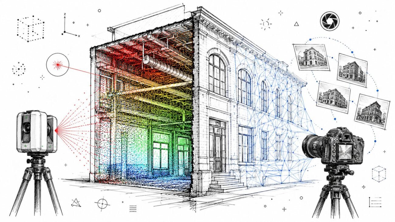
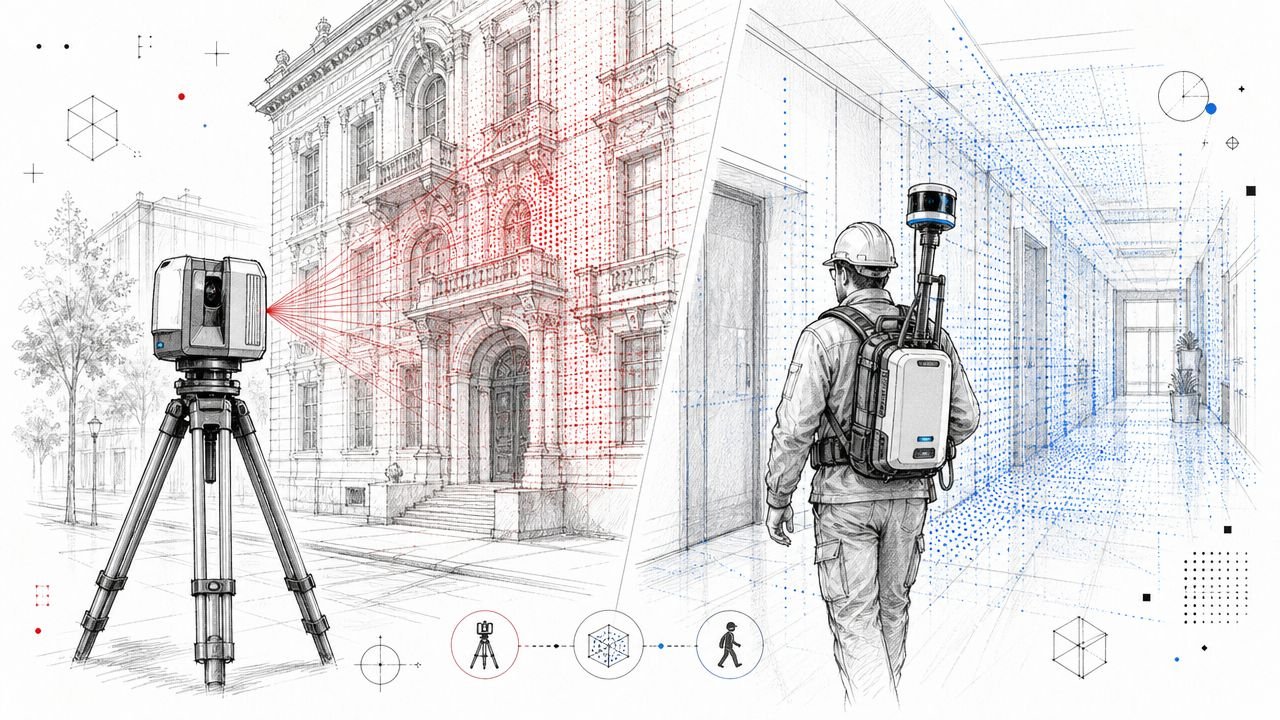
Phase-based scanners are often suitable for tight interior spaces where short-range detail and controlled coverage matter. Time-of-flight systems are useful for longer-range structural or exterior work. The problem isn't using different scanner types. The problem is mixing them without deciding how their data will be controlled, registered, and validated.
A handheld or SLAM workflow can move quickly through a large environment, but speed doesn't remove the need for independent checks. One construction-focused study reported that automatic SLAM registration can reach 25 to 50 mm global accuracy, even when the underlying LiDAR nominal error was about 3 mm. The same study measured pillar errors below 10 mm and additional measurements below 1 cm when its proposed workflow tied registration to quality checks. The construction QC study illustrates why sensor specifications alone don't establish project-level accuracy.
Plan overlap and control together
Use a deliberate overlap pattern rather than placing stations wherever the scanner can see. A practical field plan should target at least 30% overlap between adjacent positions, with stronger geometric connections where the environment lacks distinctive features. A warehouse floor with repetitive surfaces can offer less registration information than a congested plant room, even when both have similar visual coverage.
Targets should support the network, not decorate it. Distribute flat and spherical targets across the site, and plan visibility so multiple setups can observe the same control. For large projects, connect the scan network to known survey monuments or benchmarks before production capture begins. Without that connection, a locally consistent cloud may still sit incorrectly in the project coordinate system.
Environmental controls deserve the same attention. Schedule capture during low-vibration periods, prepare reflective surfaces where appropriate, and record conditions that could affect measurement or visibility. Keep a field note of blocked areas, moving equipment, unusual lighting, and surfaces that required special treatment.
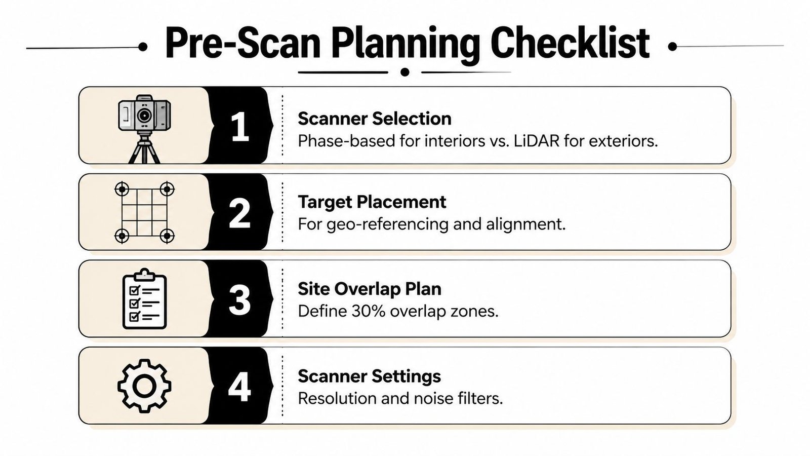
A printable pre-scan checklist should confirm:
- Equipment fit: Match scanner range and capture method to the space and intended deliverable.
- Overlap plan: Mark intended station relationships and difficult zones before arriving.
- Target visibility: Confirm target placement supports registration and coordinate control.
- Environmental notes: Record vibration, reflective surfaces, lighting, access limits, and moving objects.
- Delivery requirements: Establish coordinate system, file formats, LOD expectations, and acceptance criteria with the modeling team.
Teams that document these decisions in a scan-to-BIM workflow give the office team something more valuable than raw files. They provide the context needed to distinguish a real site condition from a capture or registration defect.
Registration and Point Cloud Validation
Registration should be treated as a measurement process, not a button press. Cloud-to-cloud alignment can establish an initial relationship between scan positions, but the final network needs target-based refinement, control checks, and independent validation.
Separate alignment from acceptance
Iterative closest point, or ICP, algorithms can find a strong initial alignment where overlapping geometry is adequate. They can also produce a visually smooth result when the geometry is repetitive or poorly constrained. Target-based registration adds an observable reference that helps lock the network to known relationships.
A registration report should be reviewed station by station. Flag setups with high residuals, weak common geometry, or unusual influence on the network. If one station pulls surrounding scans out of alignment, the correct response may be to remove and recapture that station rather than accept a local compromise.
A 2020 industrial TLS application reported consecutive setup overlap between 33% and 42%, alignment confidence metrics between 26% and 31%, and cloud-to-cloud registration errors of 0.001 m to 0.002 m. The same source reported TLS RMSE values ranging from 0.003 m to 0.021 m, with more than 90% of calculated point errors contained within 0.9 mm to 1.0 mm in static measurements. The industrial TLS application shows what controlled overlap and registration review can achieve, but those figures shouldn't be copied into a project specification without checking the actual workflow and use case.
Use a validation corridor
A validation corridor is a set of pre-measured distances distributed across the site. It can include door openings, column spacing, equipment clearances, structural grid relationships, and other dimensions that matter to the downstream model.
Compare those distances after registration and before delivery. Then inspect cross-section slices for layering, ghosting, duplicated edges, and sudden shifts. Deviation analysis against control points adds another independent check, particularly where a cloud-to-cloud comparison could hide a systematic network error.
| Metric | Acceptable Threshold | Action if Exceeded |
|---|---|---|
| Registration residuals | Use the project-specific tolerance band | Inspect the affected station, targets, and overlap before acceptance |
| Control-point deviation | Must remain within the contracted accuracy target | Recheck coordinate control and repeat the affected capture |
| Validation-corridor dimensions | Must support the intended BIM use | Hold delivery and investigate the local network |
| Cross-section continuity | No unexplained layering, ghosting, or jumps | Review noise, moving objects, and station alignment |
| Critical-zone coverage | Complete data for modeled and coordinated elements | Capture targeted supplementary scans |
The exact threshold should come from the contract and intended deliverable. ISO 10360-8 provides an international framework for acceptance and reverification testing of coordinate measuring systems with optical distance sensors, including laser scanners. It addresses accuracy and precision through P Form and P Size tests, giving metrology teams a mechanics-based way to discuss scanner validation. The ISO 10360-8 explanation is useful background when a buyer needs auditable acceptance checks rather than subjective approval.
Tolerance Thresholds for Every AEC Use Case
A scan shouldn't be specified as merely “accurate.” Accuracy has meaning only in relation to what the project team will do with the data. Early feasibility modeling, MEP coordination, steel verification, and critical retrofit work carry different consequences when the cloud is slightly outside position.
USIBD's Level of Accuracy framework uses five levels, LOA 10 through LOA 50, at a 95% confidence level. The framework maps LOA 10 to approximately 5 cm, LOA 20 to 15 mm, LOA 30 to 5 mm, LOA 40 to 1 mm, and LOA 50 to 0 to 1 mm. The USIBD LOA guidance connects those levels with uses ranging from architectural massing to forensic verification.
| Use Case | Tolerance Band | Recommended Scanner Type | Typical LOD |
|---|---|---|---|
| Early feasibility and general layout modeling | ±10 to ±15 mm | Terrestrial LiDAR or controlled SLAM, subject to validation | LOD 200 |
| Renovation as-built documentation | ±6 to ±10 mm | Terrestrial LiDAR | LOD 200 to 300 |
| MEP coordination | ±10 to ±15 mm, depending on system complexity | Terrestrial LiDAR, with targeted detailed capture | LOD 300 |
| Detailed design and clash detection | ±5 mm | Terrestrial LiDAR | LOD 300 |
| Structural steel verification | ±3 to ±5 mm | High-control terrestrial LiDAR or metrology-grade capture | LOD 300 to 350 |
| Prefabrication support | ±5 mm where the fabrication workflow requires it | High-resolution terrestrial capture | LOD 350 |
| Critical retrofit with minimal clearance | ±1 to ±3 mm | Metrology-oriented terrestrial or optical scanning | Project-specific |
These bands are practical scoping references, not universal guarantees. A construction-tolerance guide describes ±10 to ±15 mm as suitable for early feasibility and general layout modeling, ±5 mm for detailed design, clash detection, and prefabrication, and ±1 to ±3 mm for highly critical retrofit work. The construction tolerance guidance explains that a ±5 mm tolerance means the data aligns within five millimeters of the actual position.
Match LOA with model purpose
LOA and LOD answer different questions. LOA describes how accurately the captured condition is located. LOD describes the reliability and development of the modeled element. A detailed-looking model built from a cloud that doesn't meet the required LOA can create more confidence than the evidence deserves.
Don't assign one global tolerance to an entire building if the project has mixed needs. A lobby renovation, a congested MEP riser, and a steel connection may require different acceptance bands and different capture strategies. Temperature drift, reflective finishes, dark surfaces, access restrictions, and vibration can also reduce effective field accuracy, so the specification should identify critical zones rather than relying on a scanner's headline capability.
Software QA Tools and Automated Checks
Manual viewing is useful, but it catches only obvious gaps. Production teams need software checks that quantify registration, density, noise, and deviation before the point cloud reaches a modeler or coordinator.
Build a repeatable QA sequence
Start by ingesting the raw data without hiding the original files. Preserve scanner metadata, coordinate information, registration reports, and field notes. Then run automated checks for misaligned stations, excessive noise, incomplete coverage, and unexpected density changes in critical zones.
Tools such as Leica Cyclone, FARO Scene, and Autodesk ReCap support registration and point-cloud processing workflows. CloudCompare and Verity can support cloud-to-cloud or model-to-cloud comparison, depending on the project setup and licensing. The software isn't the quality system by itself. The team still needs defined rules for what triggers review, rescan, or acceptance.
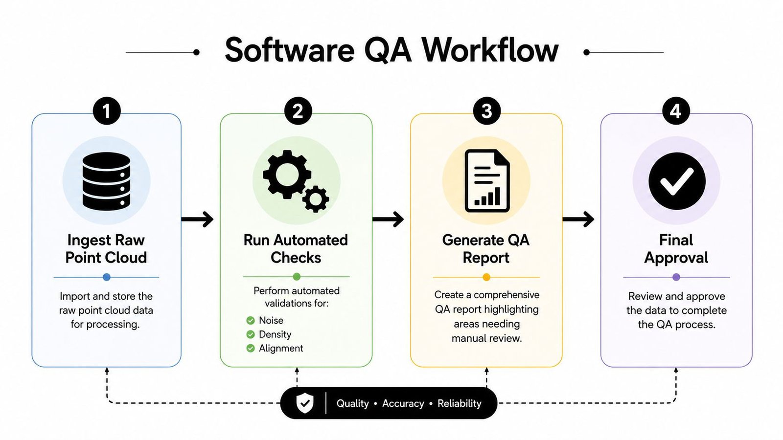
A practical batch routine can follow this order:
- Preserve raw capture: Keep original scan positions, target observations, and source metadata available for audit.
- Run registration checks: Review residuals, control relationships, overlap, and coordinate-system consistency.
- Check coverage and noise: Identify missing surfaces, moving-object artifacts, reflective-surface noise, and weak data in critical rooms.
- Compare against requirements: Use control points, known dimensions, or model-to-cloud checks tied to the project tolerance.
- Issue a QA report: Record accepted areas, exceptions, corrective actions, and the person responsible for approval.
Use deviation maps as evidence, not verdicts
A color map is a diagnostic starting point. It can show patterns that deserve investigation, but it can't tell you whether the model, cloud, coordinate system, or comparison settings caused the deviation. Review spot locations numerically and compare them with independent control or measured dimensions.
Automation should also be selective. High-volume production benefits from batch rules and exception queues, while unusual heritage geometry or congested mechanical spaces still need human review. The strongest workflow combines machine checks for consistency with a senior reviewer who understands the intended Revit, coordination, or documentation use.
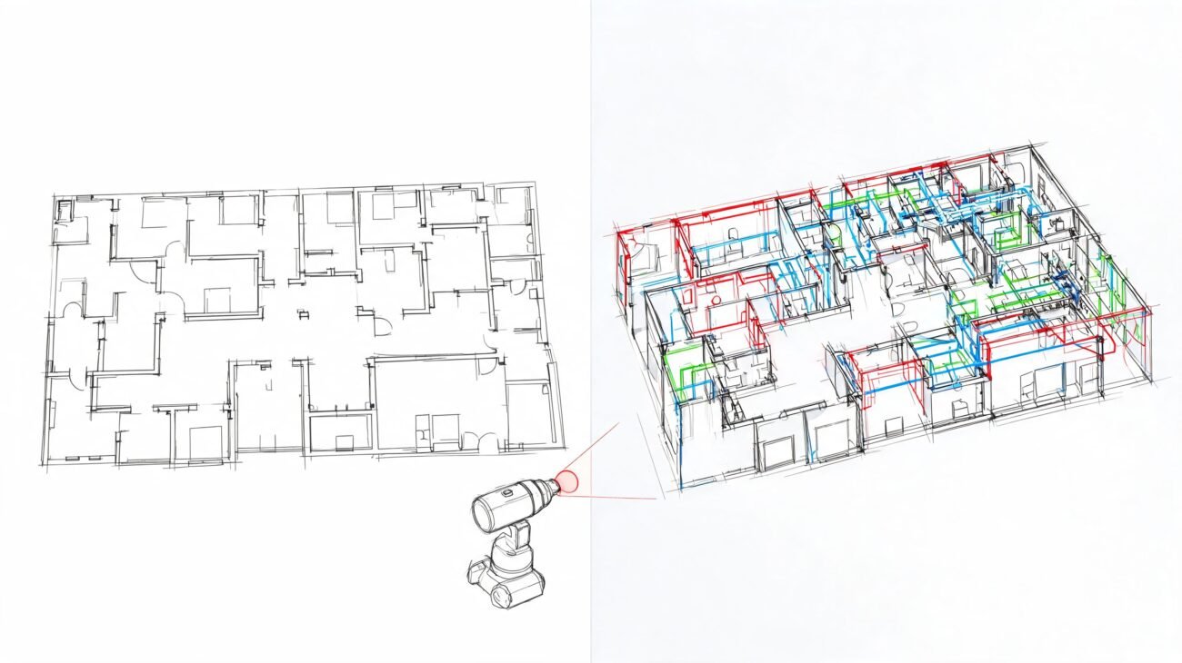
BIM Heroes describes a workflow that compares modeled elements back to the registered point cloud using deviation analysis, heat maps, spot reviews, and a deviation report included with every model. Its production services accept scanner formats from Leica, FARO, Matterport, NavVis, Trimble, and DotProduct, and can deliver RVT, IFC, DWG, NWD, or BCF files for workflows involving Revit, ReCap, Leica Cyclone, FARO Scene, Navisworks, BIM 360, ACC, Procore, and Bluebeam.
Common Scanning Mistakes and How to Fix Them
A point cloud can look clean in the viewer and still fail dimensional checks. More scan positions do not automatically improve accuracy. Extra stations may increase coverage, but they also add registration relationships, processing time, and opportunities for inconsistent setup. Plan station geometry around the surfaces and dimensions that the deliverable must support.
The mistakes that create expensive returns
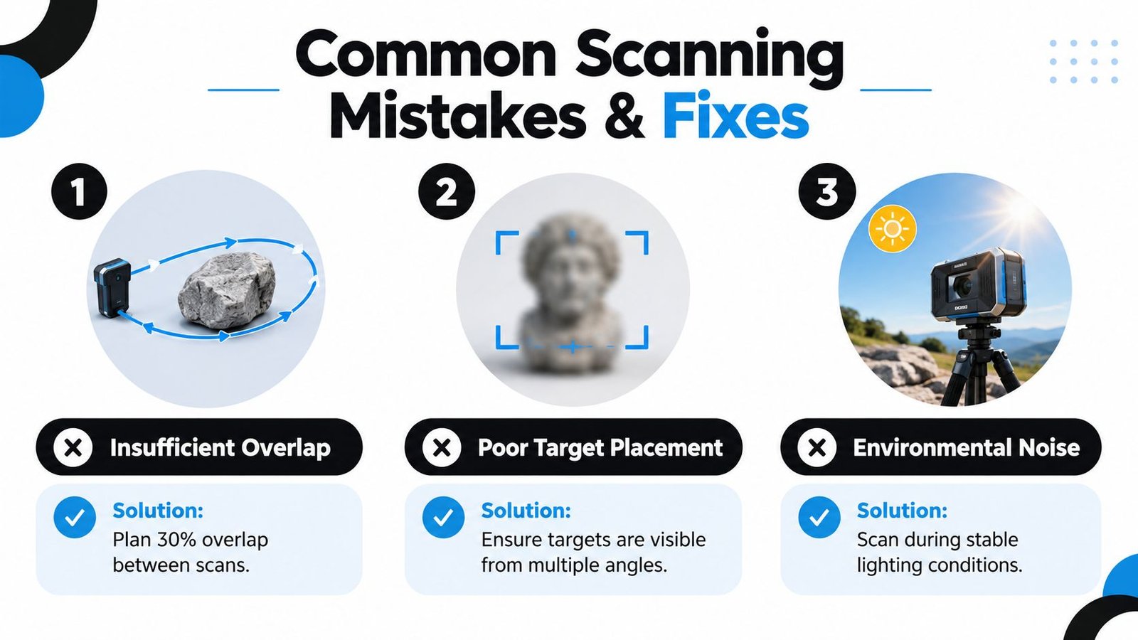
Insufficient overlap weakens registration, particularly in open or repetitive spaces. Add targeted stations around the affected zone, rerun constrained registration, and validate the network against control. A smoother alignment is not proof of accuracy.
Poor target placement leaves too few dependable common references. Position targets where several stations can see them from different angles, using target types suited to the scanner and site conditions. If the network cannot be constrained reliably, rescan before the crew leaves.
Reflective and dark surfaces can produce noisy or incomplete returns. Prepare surfaces where site conditions permit, change the capture angle or spacing, and document areas that may need interpretation. A clean render can still hide gaps behind reflective equipment or along dark structural members.
Missing control integration creates risk as the project grows. Local registration may appear consistent while the cloud is offset from survey coordinates or the design grid. Establish control early, then validate coordinates during both the field handoff and office processing.
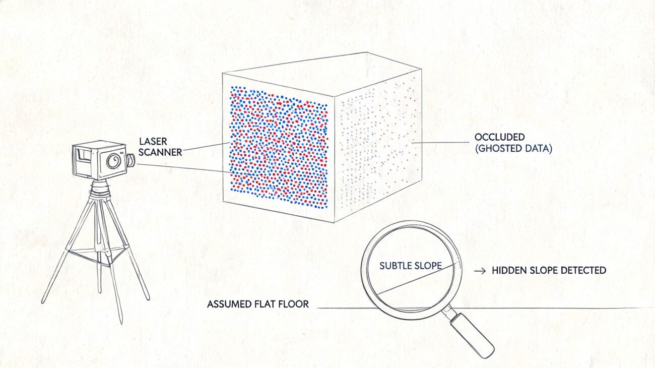
Unverified completeness causes avoidable return visits. A blocked flange, hidden ceiling zone, or missing back face may not be noticed until modeling starts. Before leaving each area, review coverage in the viewer, inspect critical elevations and sections, and compare the capture against the modeling scope.
The five-minute field gate
Use a short on-site check before demobilization:
- Critical geometry: Confirm usable coverage for every item required for modeling or coordination.
- Registration health: Review key station relationships and control points against the planned criteria.
- Occlusion review: Record blocked, reflective, or inaccessible areas and their likely effect on the deliverable.
- Coordinate check: Confirm alignment with project control or the survey reference.
- Rescan decision: Have the field lead approve the area or identify targeted additional capture.
A construction quality-control case study reported 97.8% of scanned productions within acceptable tolerance and 2.2% defective. The result applies to that specific workflow, not every project. Its practical lesson is more useful than the percentage itself: connect point-cloud checks to defined tolerance validation, and use visual inspection as supporting evidence rather than the acceptance criterion. The case study source demonstrates that approach.
Your Quality Control Checklist Framework
A useful checklist has three gates, and each gate has an owner. That structure turns quality from a personal preference into a repeatable production artifact that can travel with the project from field capture to modeling and coordination.
Pre-scan gate
The field lead confirms equipment calibration records, scanner selection, control integration, station geometry, overlap planning, target visibility, environmental risks, and required deliverable formats. The BIM manager confirms the intended use, coordinate system, tolerance band, LOD target, and critical zones before capture begins.
Field QA gate
The scanning lead reviews registration health as capture progresses rather than waiting for office processing. The team verifies target coverage, checks critical areas for occlusion, records environmental conditions, and marks any location that needs a supplemental scan.
Post-processing gate
The processing team validates registration, control, coverage, density, noise, and model-to-cloud deviation. The deliverable package should include the agreed report, exceptions, coordinate information, file naming, and format compliance. For scan-to-BIM work, the point-cloud reference library can support consistent handling of source data and production references.
Version the checklist by project phase and revision. Assign accountability at each gate, record the acceptance date, and preserve the evidence used for approval. ISO/IEC 8801:2026 defines a structured SOP for curation and quality control of 3D scanned data and associated label data, including checks for measurement accuracy, label completeness, and consistency. The ISO/IEC 8801:2026 reference provides a standards-based example of why QC should be managed as an organized SOP with defined inputs, outputs, and validation steps.
Firms that document this process protect margin and make outsourcing easier to manage. A scan provider can capture the site, a production partner can model it, and the owner can review a clear acceptance trail instead of arguing over whether a color map “looks right.”
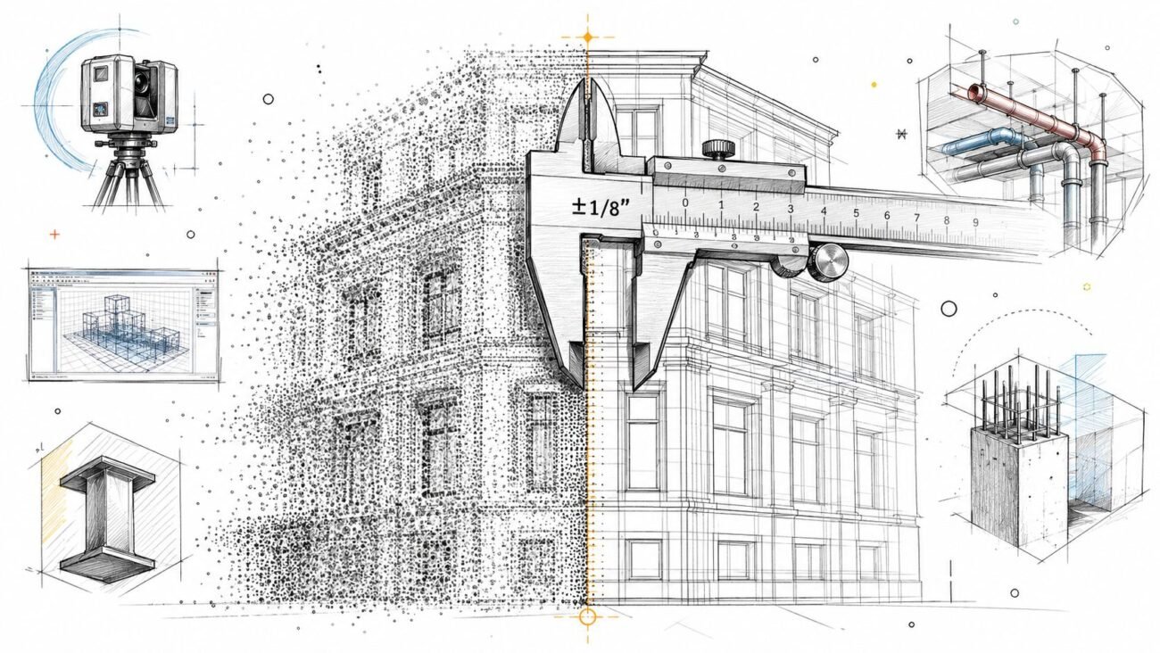
BIM Heroes can process point clouds into Revit, IFC, DWG, NWD, or BCF deliverables at LOD 200 to 350, with accuracy verified to ±1/8 inch and a deviation report included with every model. Send your scan data or request a free consultation with BIM Heroes for a free LOD recommendation and pricing within 24 hours.