Trying to recess a custom millwork panel into a wall is where a lot of teams discover the difference between a model that looks right and a model that behaves right. The panel appears to overlap correctly in one view, then the section stays messy, edge lines don’t clean up, and Join Geometry only makes the condition harder to read. That’s usually when RFIs start later, because the model never established an actual subtractive relationship.
That’s where Cut Geometry Revit becomes a production tool, not just a command on the ribbon. It’s the right move when one element needs to remove volume from another and the standard hosted behavior won’t do it cleanly. In live documentation sets, that matters because the cut has to stay predictable through sections, elevations, and detail development.
Teams working through Revit modeling workflows run into this constantly on interiors, custom families, retrofit conditions, and geometry-heavy packages. The difference between a clean cut and a fake visual workaround is usually the difference between stable documentation and downstream cleanup.
Introduction
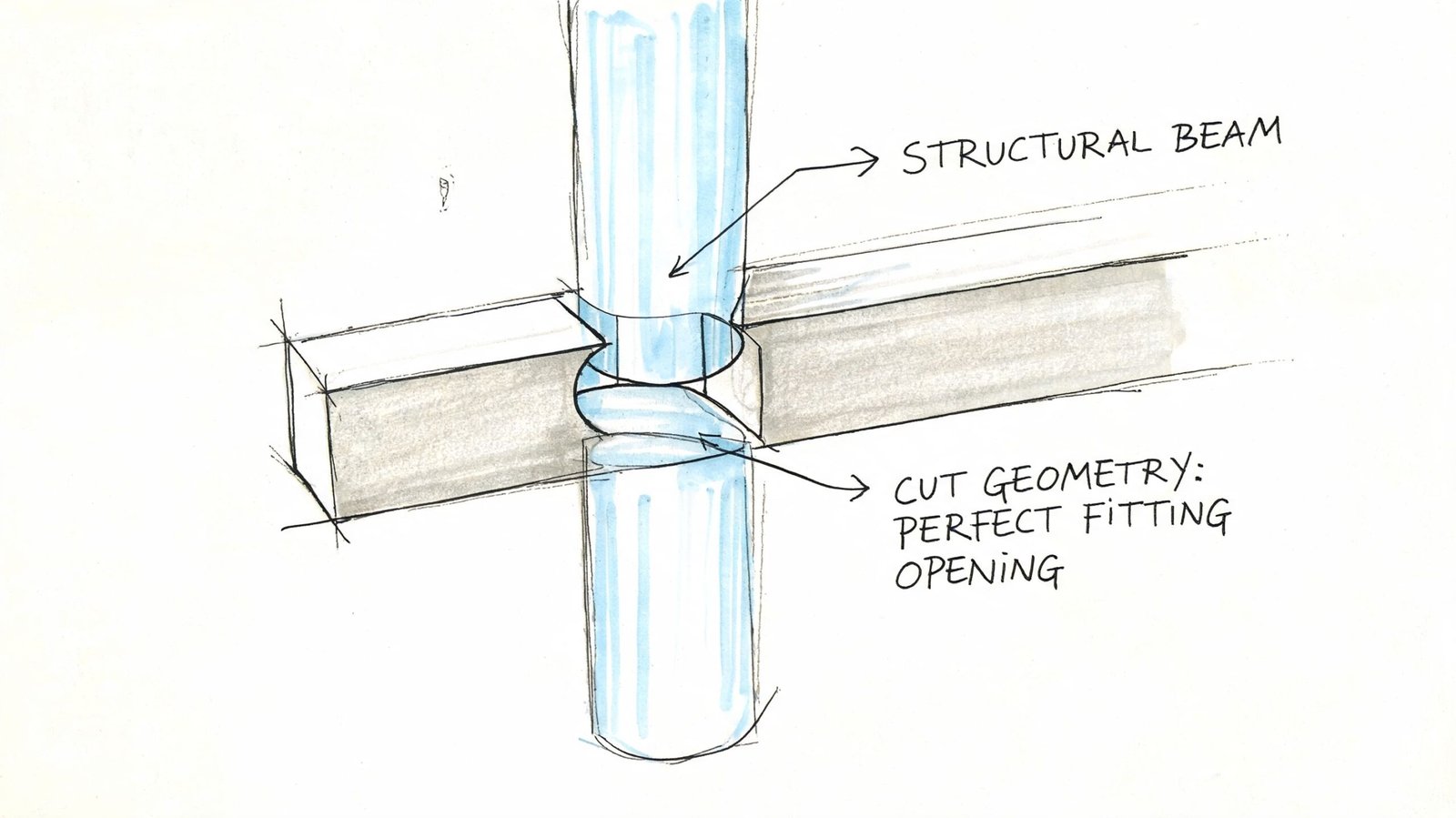
A technician has a wall niche, a countertop opening, or a recessed cabinet that refuses to behave. The geometry overlaps, but it doesn’t fully subtract. In plan it might look close enough. In section, the problem shows up immediately.
The cut geometry tool revit is built for that exact condition. It tells Revit that one element is supposed to remove material from another, and that relationship becomes part of the model logic instead of a visual compromise.
Used with discipline, it helps teams keep families clean, details coordinated, and documentation reliable. Used casually, it creates hidden dependencies that show up later when phases change, options split, or somebody edits the wrong element in a workshared model.
What the Cut Geometry Tool Actually Does
The Revit Cut Geometry tool creates a directional subtractive relationship between two elements. One element gives up volume. The other defines the void. Revit then treats that subtraction as model geometry, not as a view-specific fix.
Selection order controls the result. The first pick is the host. The second pick is the cutter. If that order is reversed, the cut may fail, or worse, appear to work in a way that is hard to spot until a section, detail, or schedule exposes it. Novedge’s discussion of Revit cut geometry best practices also notes a material precedence constraint, so teams should verify material behavior after the cut instead of assuming the relationship is neutral.
A successful cut persists across views because the host element has been modified by that relationship. Plan, section, elevation, and 3D should all report the same subtraction. That consistency is the reason production teams use the tool. If the opening needs to read reliably in documentation, the model needs a real cut, not a masking move or a graphic workaround.
The tool also creates dependency. That matters in live project files. If the cutter is deleted, swapped, excluded from an option, or changed in a way that breaks compatibility, the host can lose the cut and the issue may not surface until sheets are already in progress.
There is also a clear difference between family-level cutting and project-level cutting. In families, cuts are often built into the component with void forms and controlled parameters. In projects, Cut Geometry is used after placement to force a relationship between elements already in the model. Those two approaches can produce a similar visual result, but they do not carry the same maintenance risk.
Use the tool for deliberate volume removal. Holes, recesses, notches, and blockouts fit that category. Do not use it as a general cleanup command when the actual problem is poor family construction, the wrong hosting strategy, or a condition that Revit already handles better with native openings or embedded voids.
Cut Geometry vs Join Geometry
Users often don’t misuse Cut Geometry because the command is hard. They misuse it because they confuse it with Join Geometry. The tools can both make intersections look cleaner, but they solve different problems.
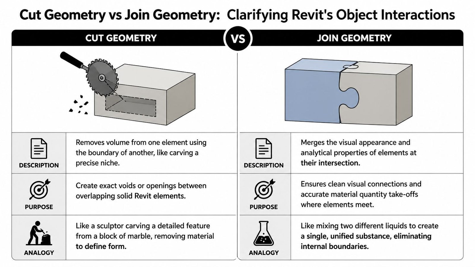
Where Join Geometry belongs
Join Geometry is for boundary resolution. Two elements meet. Revit needs to know how their edges, fills, and material boundaries should clean up at the intersection.
That’s useful for common building conditions such as walls meeting floors, structural members intersecting, or layered assemblies resolving at a seam. The goal is a cleaner intersection and more coherent graphics.
Where Cut Geometry belongs
Cut Geometry is for volume removal. One element actively subtracts from another. You use it when the issue is not “these objects meet awkwardly” but “this object needs to carve out space from that object.”
Think about it this way:
- Join Geometry cleans the meeting line between two solids.
- Cut Geometry creates a void condition by removing mass from a host.
- Hosted openings are best when Revit already understands the relationship natively.
- Family voids are usually better when the cut is intrinsic to the component every time it’s used.
Join for seams. Cut for holes.
That’s the rule most production leads end up repeating.
The common mistake is reaching for Join Geometry because it’s nearby on the ribbon and gives an immediate visual change. But a joined condition can still leave you without an actual recess, opening, or clearance. That becomes obvious in sections, schedules, or detail coordination.
Another mistake is stacking tools. A family may already include host-cut behavior, then someone adds project-level Cut Geometry on top of it, and someone else joins the result to nearby geometry. The model may still look acceptable for a while, but it’s now carrying multiple overlapping behaviors for one condition. That’s where predictability starts to drop.
Practical Use Cases for the Cut Geometry Tool
A common production problem goes like this. The plan looks acceptable, but the section shows that a recessed cabinet never removed wall material, or a countertop opening only works in coarse view and falls apart in coordination. Cut Geometry earns its place in exactly those cases. It handles model conditions that need a real subtraction, not a graphic workaround.
Conditions where standard hosting falls short
Recessed electrical cabinets, built-in shelving, and access panels are typical examples. The family may be hosted correctly, but the host relationship still may not produce the recess depth, finish break, or backing condition the design set expects. A direct cut gives precise control over what volume is removed and where the cut stops.
Casework and interiors generate many of these situations. An undermount sink, a service notch in a gable, a cutout in a filler, or an open-back condition behind equipment often needs explicit geometry. If the team tries to fake that with detail lines, masking, or overlapping solids, the error usually appears later in sections, enlarged views, or quantity checks.
Structural use is similar, but the risk is higher. Beam penetrations, slab recesses, and concrete blockouts need to read clearly in coordination views. If the void condition is ambiguous, somebody in the field asks for clarification, and the model stops being a dependable reference.
Custom geometry that does not fit a native opening workflow
Facade work is another place where Cut Geometry can help, but it needs restraint. A custom panel cutout or a shaped recess in a nonstandard assembly can be valid. Repeating that same logic across a full elevation at project level can also make the model harder to maintain. If the subtraction is part of the panel definition every time, build it into the family instead of creating one cut after another in the project.
Site and massing models also produce one-off conditions where native tools do not give enough control. Sunken zones, carved massing studies, or custom terrain-related forms may need a direct subtraction to communicate the design clearly. That can be appropriate during development, provided the team knows whether the geometry is temporary study content or something that must survive into documentation.
A few use cases that usually justify Cut Geometry in production:
- Recessed wall elements such as cabinets, specialist equipment, and niche conditions
- Millwork modifications in countertops, backs, fillers, and cabinet components
- Structural blockouts and penetrations that need explicit geometry for coordination
- Custom facade components with subtractive forms that standard openings do not support
- Massing or site studies where a direct cut is clearer than forcing a native host behavior
The decision is less about whether Revit can make the cut and more about whether the cut will stay readable, editable, and coordinated by the next person who touches the model. That is the standard worth using.
How to Use the Cut Geometry Tool Step-by-Step
A typical failure goes like this. The cut looks fine in plan, the sheet set moves ahead, and someone catches the bad geometry only after sections or details are issued for review. That is why the command itself is the easy part. Reliable verification is the actual workflow.
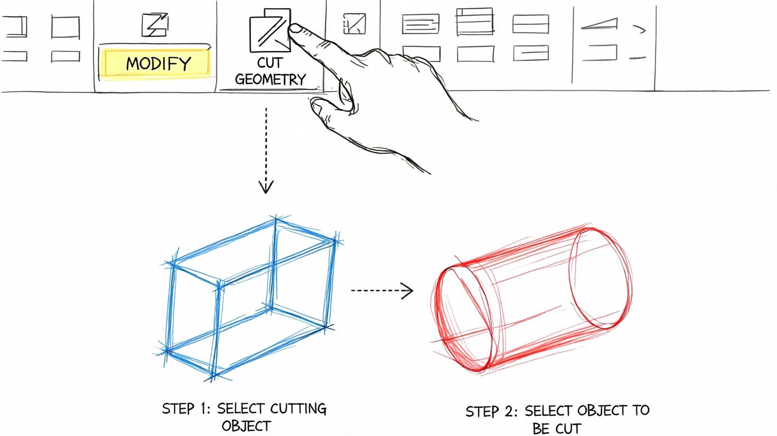
The sequence that usually works
Start from the Modify tab in the Geometry panel and choose Cut. Select the element that will lose material first, then select the element doing the cutting. Selection order matters here. If the order is wrong, the command can fail or produce a result that is technically valid but wrong for documentation.
Revit applies the subtraction immediately when the relationship is allowed. Verify it right away in a section or 3D view. Plan can hide partial cuts, stray edges, and geometry that only looks correct at coarse detail. If your team has had unexplained display issues before, the same model habits often show up in hidden geometry errors that break Revit models.
Use Uncut Geometry to remove the relationship cleanly. Do not patch a bad cut with Join Geometry, masking regions, or category overrides. Those fixes usually survive just long enough to confuse the next person who edits the model.
Where technicians usually lose control
The command is quick. The decision behind it should be slower.
Use project-level Cut Geometry when the subtraction is tied to one local condition and may need to change with coordination. If the subtraction is part of the object every time it is placed, build that logic into the family instead. Production models stay cleaner when repeatable behavior lives with the component rather than as a stack of project edits.
A reliable check is simple:
- Cut the geometry
- Open a section or 3D view
- Confirm the host lost the correct material
- Confirm the cutter is still the element you expect
- Uncut and rebuild if the result looks forced or dependent on view tricks
I usually tell teams to trust the section, not the plan. A bad cut can sit in the model for days because 2D linework looks acceptable while the actual subtraction is wrong.
Project environment versus Family Editor
Family Editor and the project environment serve different purposes. In families, voids are usually the better choice when the cut defines the product. In the project, Cut Geometry is better for one-off adjustments tied to a specific location, coordination issue, or construction condition.
Use this rule set:
- Family-level void for repeatable component behavior
- Project-level Cut Geometry for unique placed conditions
- Uncut and rebuild when several cuts start interacting and the edit path stops being obvious
Version differences also affect workflow. In Revit 2024, Autodesk added multi-cut options to the Cut/Uncut Geometry tools through the ribbon dropdown, which makes repetitive cutting tasks faster in practice, as shown in this Revit 2024 workflow reference. That change helps with speed, but it does not remove the need to verify every subtraction in the right view before the model goes to documentation.
Common Limitations and Failure Modes
A typical failure looks like this. The cut worked yesterday, the view still looks close enough in plan, and now a section shows the host never resolved cleanly. That is how small geometry edits turn into documentation noise and late coordination questions.
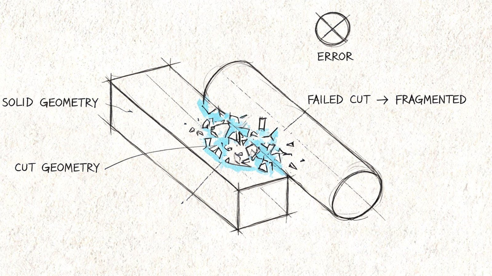
Why a valid-looking cut still breaks
Cut Geometry is not just a click sequence. It depends on category rules, existing relationships, and whether Revit can resolve the subtraction into stable model geometry. A cut can fail even when the selection order is correct.
Existing joins are one of the first things to check. Users in this AUGI thread on Cut Geometry failures describe cases where Cut Geometry would not execute because prior Join Geometry relationships or tight wall conditions were already controlling the result. In production terms, the failed cut is often a symptom. The underlying issue is that another geometry rule got there first.
Category compatibility also limits what you can do. Not every family category can cut every target, and some elements that look like they should behave as cutters will not. That is one reason teams sometimes use Generic Models for controlled one-off cuts, although that flexibility comes with its own management cost later if category logic starts drifting from the actual object purpose.
Hidden cutters cause another common misunderstanding. Hiding the cutting element does not heal the host. The subtraction still exists in the model, so the host stays cut. That catches out less experienced users during view cleanup and can leave a model looking inconsistent from one view to another.
Production risks that show up later
The bigger problems usually appear after the original author has moved on. Phase edits, design options, and family revisions can all break the logic behind a cut without making the failure obvious right away. The geometry may still display, but the relationship stops being easy to trust or troubleshoot.
Worksharing makes that worse. If the host, cutter, and related joins sit across different users or worksets, diagnosis slows down fast. Revit is not surfacing a clean audit trail for these relationships, so the team ends up reverse-engineering intent from the result.
Family-level voids can also conflict with project-level cuts. Revit may allow both, but that does not mean the setup is reliable. If the family already owns the opening condition, adding a project cut on top usually makes the model harder to maintain and easier to break during later edits.
Use a quick triage pass before rebuilding anything:
- Check for existing joins that may be overriding the cut
- Confirm category compatibility between cutter and target
- Review phases, options, and family changes if a cut stopped behaving after model updates
- Inspect the result in section and 3D to confirm actual subtraction, not just a view condition
- Remove the bad relationship with Uncut Geometry before trying another method
Teams that keep seeing these failures should also review the wider pattern of hidden geometry errors that break Revit models. Repeated cut failures usually point to a model control problem, not a tool problem.
Best Practices for Clean Production Workflows
The most reliable rule is simple. If a cut is always part of the component, build it into the family. Project-level cuts should be the exception, not the default. That keeps the behavior portable and easier to audit later.
When project cuts are necessary, document them. A naming convention for cutting elements, a consistent category strategy, and a team note in the model log will save time the next time someone has to troubleshoot a missing recess or failed opening. If your team builds custom components often, this is also where stronger Revit family creation standards pay off.
Habits that improve predictability
A few habits consistently reduce cleanup:
- Prefer family voids when the subtraction belongs to the object everywhere it appears
- Use Generic Model thoughtfully when category flexibility becomes a problem
- Verify in section and 3D before issuing sheets or coordination views
- Avoid cross-workset dependency where possible because hidden ownership issues make troubleshooting slower
- Remove bad cuts cleanly with Uncut Geometry before trying a different method
Good production teams don’t just know how to make a cut. They know how to leave a model in a condition the next person can understand.
The goal isn’t to use Cut Geometry everywhere. The goal is to use it where it gives the model a clearer, more stable logic than the alternatives.
Conclusion
The cut geometry tool revit is one of those commands that looks small on the ribbon and carries big consequences in production. It’s the right tool when one element must remove volume from another and hosted behavior or Join Geometry won’t deliver a dependable result.
Used carefully, it supports cleaner sections, fewer geometry workarounds, and better model predictability. Used casually, it creates hidden relationships that are easy to forget and expensive to fix later. Most geometry cleanup problems aren’t just modeling issues. They’re decision issues about where the behavior belongs.
If your team is spending too much time deciding whether a geometry fix belongs in the project or inside the family, that’s a production systems problem, not just a software problem. BIM Heroes helps AEC teams build cleaner Revit workflows, stronger family standards, and more predictable modeling frameworks so geometry behaves the way documentation needs it to.