


A stalled permit set usually doesn't fail on the floor plan. It fails because the reviewer can't prove the plumbing riser diagram makes the building work from story to story, especially when a vent connection, cleanout, or branch tie-in is missing on one level. In practice, the riser is the sheet that shows whether waste drains, vents breathe, and water reaches the right fixtures before anyone pours slab or closes shafts. If you're producing or reviewing plumbing docs, you need a drawing that's clear enough for plan check and disciplined enough for coordination, not just a neat vertical sketch.
Introduction
A plumbing riser diagram is the vertical proof sheet in a plumbing set. Floor plans show fixture locations, but the riser shows how supply, DWV, drain, waste, and vent systems stack through the building, and that's what lets a reviewer verify the plumbing plan requirements before approval.
When a permit is under review, the pain usually shows up in the gaps. A branch is missing, a stack is unlabeled, or the vent path never reaches the roof, and the whole package gets sent back. That's why teams that treat the riser as a code document, not a drafting afterthought, tend to move faster through plan check and field coordination.
For firms that outsource production, this is also where consistency matters most. Clean risers reduce RFIs, support MEP coordination, and give project managers a drawing that's easier to trust when it's time to issue for permit or fabricate.
Understanding plumbing riser diagrams and systems
A plumbing riser diagram is a schematic, non-scaled vertical map of how the plumbing system stacks across floors. It does not replace the plan view. It supports the plan by showing the continuous path from main entry to branches, risers, and terminal fixtures, which is why jurisdictions can require single-line risers for plan approval rather than treating them as optional coordination graphics. The Texas archive record shows the format has long been used as a dedicated “Plumbing Riser Diagram” document, and that matters because this is a mature permit drawing type, not a modern convenience. Texas History archive reference
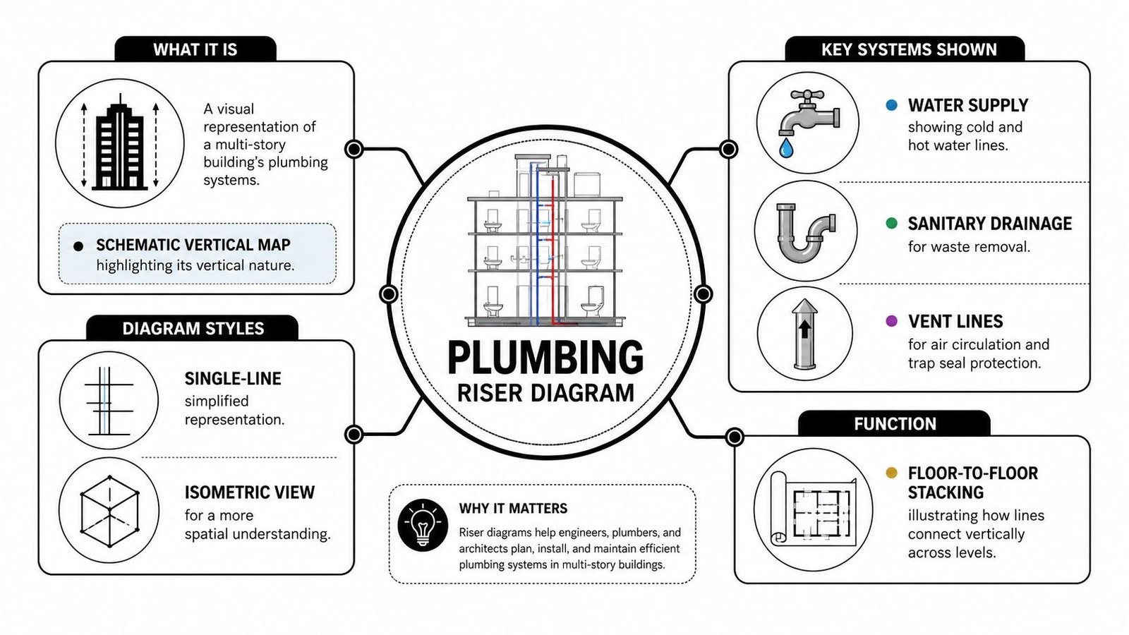
Practical rule: if a reviewer cannot trace water in, waste out, and air movement through the vents, the drawing is not finished yet.
What the riser has to show
The riser usually carries the vertical logic for water supply, sanitary drainage, and venting. In many projects it also shows recirculation, storm, or gas where those systems are relevant to the building type, plus critical devices like isolation valves, pressure-reducing valves, backflow preventers, and pressure-zone boundaries.
That is why the drawing works best as a system-by-system map. For BIM and production teams, the value is simple, one sheet can reveal whether a multi-story shaft, branch, or fixture group is buildable before coordination gets expensive. For a practical drafting standard, see the guidance at BIM Heroes plumbing design.
Why this matters in review
Reviewers use the riser to confirm that the vertical system is coherent. California permit guidance says riser diagrams are required with building permit applications to demonstrate engineered pipe sizing and system configuration, and Fairfax County's Technical Bulletin 19-07 says axonometric BIM-style projections can be submitted but cannot be the only representation, because single-line risers remain the mandatory review standard. The code logic behind that stance is straightforward, a riser has to show vertical distribution and control points clearly enough for review. For the broader code context, see the International Code Council's plumbing code resources.
For teams working in Revit or CAD, that means the riser is not just a coordination artifact. It is a permit deliverable that has to be readable, traceable, and complete.
Common plumbing symbols and abbreviations
Symbols on a riser are conventions, not universal law. Every office standard is a little different, so the legend is the source of truth, but a lot of sets use the same shorthand because reviewers, fabricators, and field crews expect it.
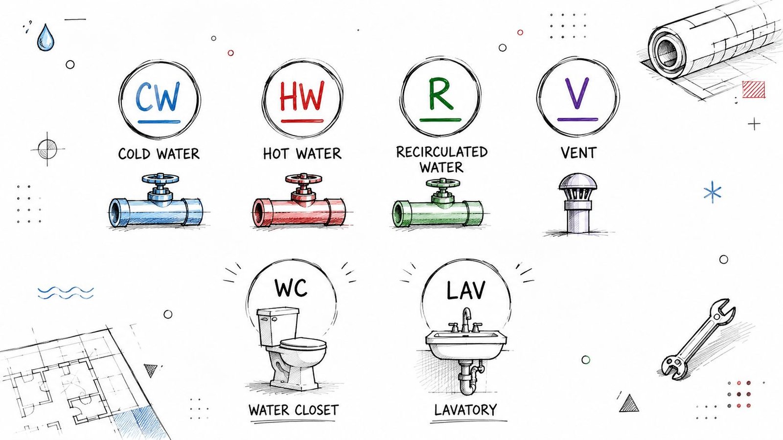
Common abbreviations you'll see
| Symbol or abbreviation | Meaning |
|---|---|
| CW | Cold water |
| HW | Hot water |
| R | Recirculation or return, depending on office convention |
| V | Vent |
| WC | Water closet |
| LAV | Lavatory |
| FD | Floor drain |
| CO | Cleanout |
| PRV | Pressure-reducing valve |
| BFP | Backflow preventer |
| SV | Shutoff valve |
Pipe line styles often vary too. A heavier line, dashed line, or different layer may indicate a specific system, but that convention only works when the legend is clear and the office standard stays consistent from sheet to sheet.
How to keep the legend useful
The best risers do three things at once. They label the system, identify the fixture group, and call out the pipe size or special device where it matters. That makes the drawing easier to read during plan review and easier to use in the field, especially when multiple trades are coordinating in tight shafts.
A lot of firms also separate supply and waste logic in the graphic itself. The Illinois State Board of Education plumbing training material notes that a riser can be split into a supply diagram and a waste-and-vent stack diagram, which is a practical way to keep the drawing legible when the system gets crowded. If you're formalizing how that looks in production, a good starting point is an isometric plumbing diagram workflow that keeps the legend, linework, and labeling disciplined.
Keep the symbol set boring and consistent. Reviewers don't reward creativity in a plumbing legend.
Layout and drawing conventions
Good riser layout starts with stacking the building, not decorating the page. Each floor's branch taps should line up vertically so the reviewer can see how the system behaves floor to floor, and the stacks should be labeled clearly enough that a coordinator can trace them without guessing which branch belongs to which level.
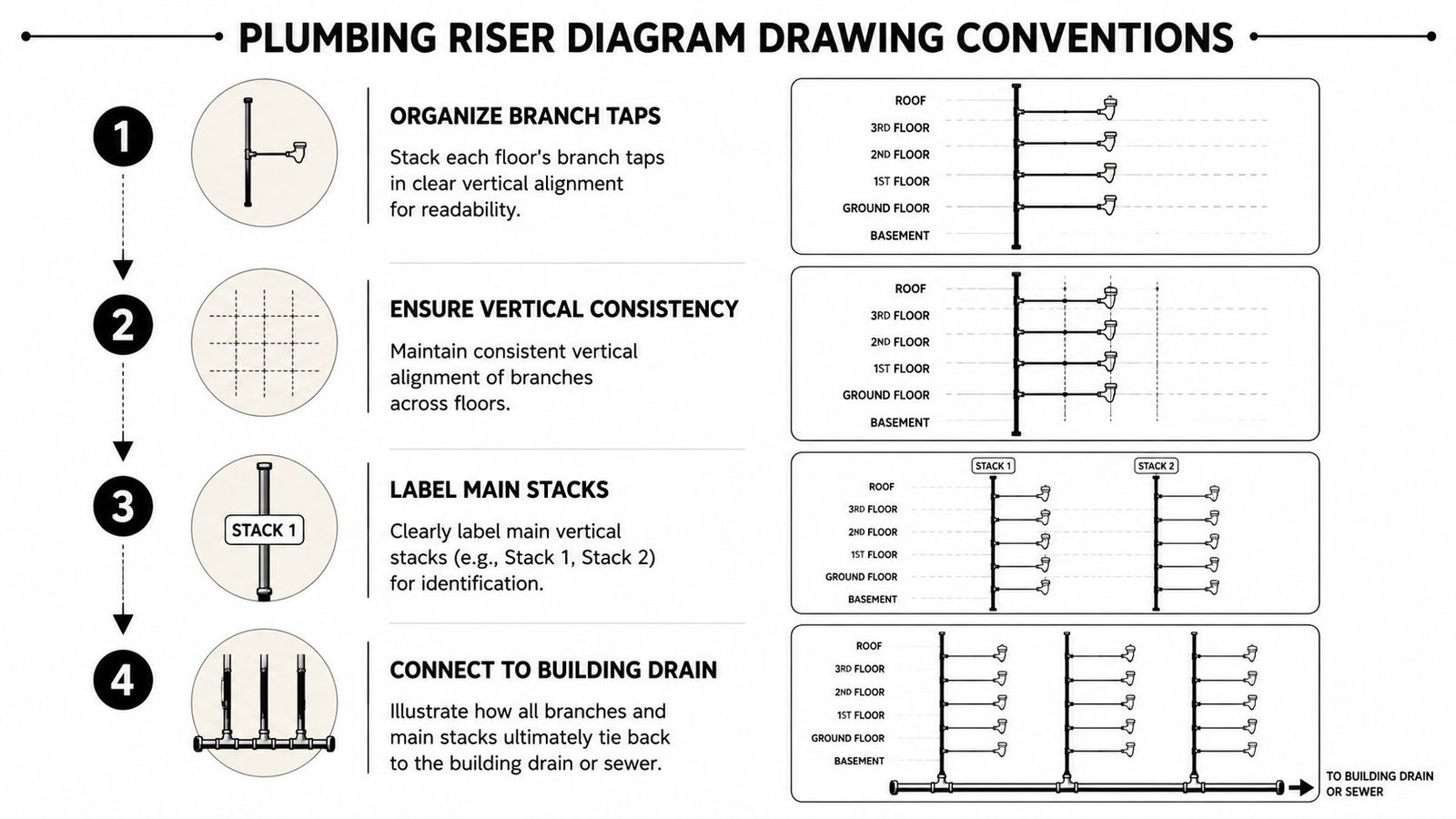
Single-line first, clarity always
A single-line or axonometric view can both work, but the priority is readability. The riser is intentionally not to scale, so it should never be used as a spatial substitute for the floor plan, especially when shaft widths, beam offsets, or trade congestion matter.
In Revit, the cleanest production sets usually separate hot water, cold water, and DWV into different views or filters so the linework stays legible. In CAD, locked layers and consistent plot styles do the same job. The goal is less about fancy graphics and more about reducing annotation noise during permit and coordination reviews.
Labels that actually help
Use floor callouts, stack labels, and device tags that mean something to the field team. A note for a cleanout access point, a break line for hidden floors, or a slope callout near drainage changes can save a reviewer from having to infer what the model meant.
Field-tested habit: if a branch changes direction, changes level, or crosses a shaft boundary, label it. Silent geometry creates RFIs.
For teams standardizing production, the riser should behave like every other controlled drafting output. That's where disciplined modeling helps, and it's also where outsourced MEP engineering or plumbing production can keep the set clean when the internal team is already overloaded.
What plan reviewers look for
Plan reviewers check whether the system works in code terms, not whether the sheet looks tidy. Under the IPC or UPC, depending on your jurisdiction, they want to see proper venting, cleanout access, drainage slope, fixture connection logic, and pipe sizing that matches the fixture load on the project.
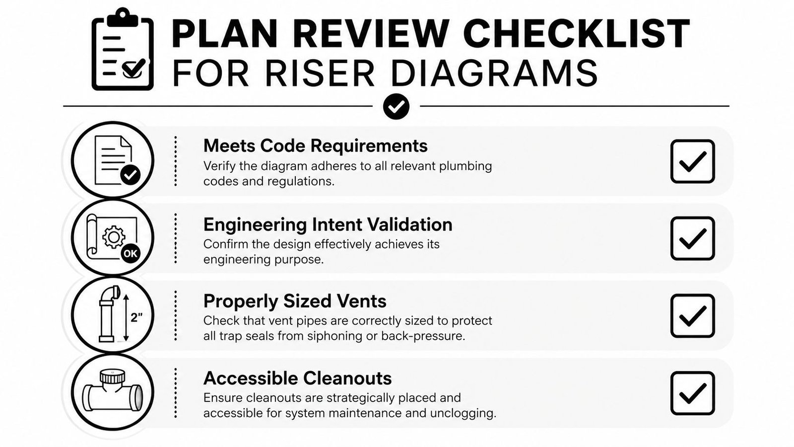
The review mindset
A reviewer typically cross-checks the riser against the floor plan to confirm the branches, fixtures, and stacks line up. If a lavatory appears on the plan but never shows up in the riser, or if a vent path stops short of its intended route, the permit reviewer has a legitimate reason to kick the set back.
The practical standard is simple. The drawing should show enough information for code review without forcing the checker to reconstruct the system from memory. That means cleanout locations, venting logic, pressure-zone boundaries where relevant, and valve placement should be visible, not buried in a note somewhere else.
A good check set also needs to match how the team will build the job. If the permit sheet and the production set disagree, the reviewer sees confusion and the field sees rework. That is why many teams tie the permit riser to their plumbing shop drawings workflow early, so the same system logic carries from code review into coordination and fabrication.
Effective Labeling
Use floor callouts, stack labels, and device tags that mean something to the field team. A note for a cleanout access point, a break line for hidden floors, or a slope callout near drainage changes can save a reviewer from having to infer what the model meant.
Field-tested habit: if a branch changes direction, changes level, or crosses a shaft boundary, label it. Silent geometry creates RFIs.
For field-use and review, the strongest risers are simplified, non-scaled vertical schematics that trace water, waste, and vent paths one system at a time from main entry to terminal fixtures, supported by a QA checklist, as noted in field guidance on riser diagram reading. That standard is the one to target when a permit set has to survive both review and construction.
Common mistakes and how to avoid them
The most expensive riser mistakes are usually quiet ones. A vent connection is left off. A stack sizing note is wrong. A shaft location is drawn without thinking about where the other trades are going to land. Those errors can pass a quick internal glance and still trigger rejection or a painful field correction later.
Where sets go wrong
Missing or improper venting is a classic failure point because the traps need the right pressure balance to stay sealed. If the vent path isn't legible, plan checkers often treat the system as incomplete.
Inaccessible cleanouts are another common miss. A cleanout that exists on paper but ends up buried behind finish work or hidden in a shaft without access is the kind of detail that turns into an RFI or a callback.
The coordination trap
Risers also fail when they're built in isolation from the rest of the model. That's where MEP coordination and clash review matter, because a riser that ignores duct routing, beam lines, or crowded chases can look fine in 2D and still fail in the model. The same logic applies when plumbing is being coordinated alongside duct or electrical work, because the shaft only works if every trade respects the same space.
Best fix: tie the riser back to the floor plan, then compare it against the coordinated model before the set goes out the door.
A nuanced review of industry practice notes that missing vent connections, incorrect stack sizing, and uncoordinated shaft locations are common failure points that lead to plan-review rejections and on-site headaches. That tracks with what production teams see every week, the riser isn't just a diagram, it's a coordination checkpoint.
Conclusion and next steps
A solid plumbing riser diagram proves the system works before anyone starts cutting, pouring, or closing walls. When the drawing is clean, code-aware, and coordinated with the rest of the MEP set, it protects schedule, reduces RFIs, and gives reviewers fewer reasons to stall the permit.
BIM Heroes supports teams that need plan-review-ready plumbing documentation, coordinated Revit production, and disciplined shop drawing output without losing control of the standard. If you need help with MEP engineering or plumbing drawings that hold up in review, bring us the set and we'll help you tighten the workflow.
BIM Heroes produces coordinated plumbing risers, MEP documentation, and outsourced Revit production that's built for permit review and field use. If you're comparing approaches or need a cleaner path from model to submittal, BIM Heroes can help you scope the work and move it forward with less rework.