Meta title: Duct Design vs. Duct Coordination Explained
Meta description: Duct design and duct coordination aren't the same thing. Here's the distinction, and where MEP modeling changes outcomes.
Category: MEP Engineering
On a lot of projects, someone says “the duct design is done” when what they really mean is the airflow path has been sketched, sizes have been assigned, and the system works on paper. That statement says nothing about whether the duct fits above the corridor ceiling, clears the transfer beam, stays out of the sprinkler main, or leaves enough room for access panels and fire dampers.
That confusion causes real damage. Engineering teams think performance has been addressed. Field teams assume constructability has been checked. Then the conflict shows up during coordination, permitting, fabrication, or worse, after installation starts.
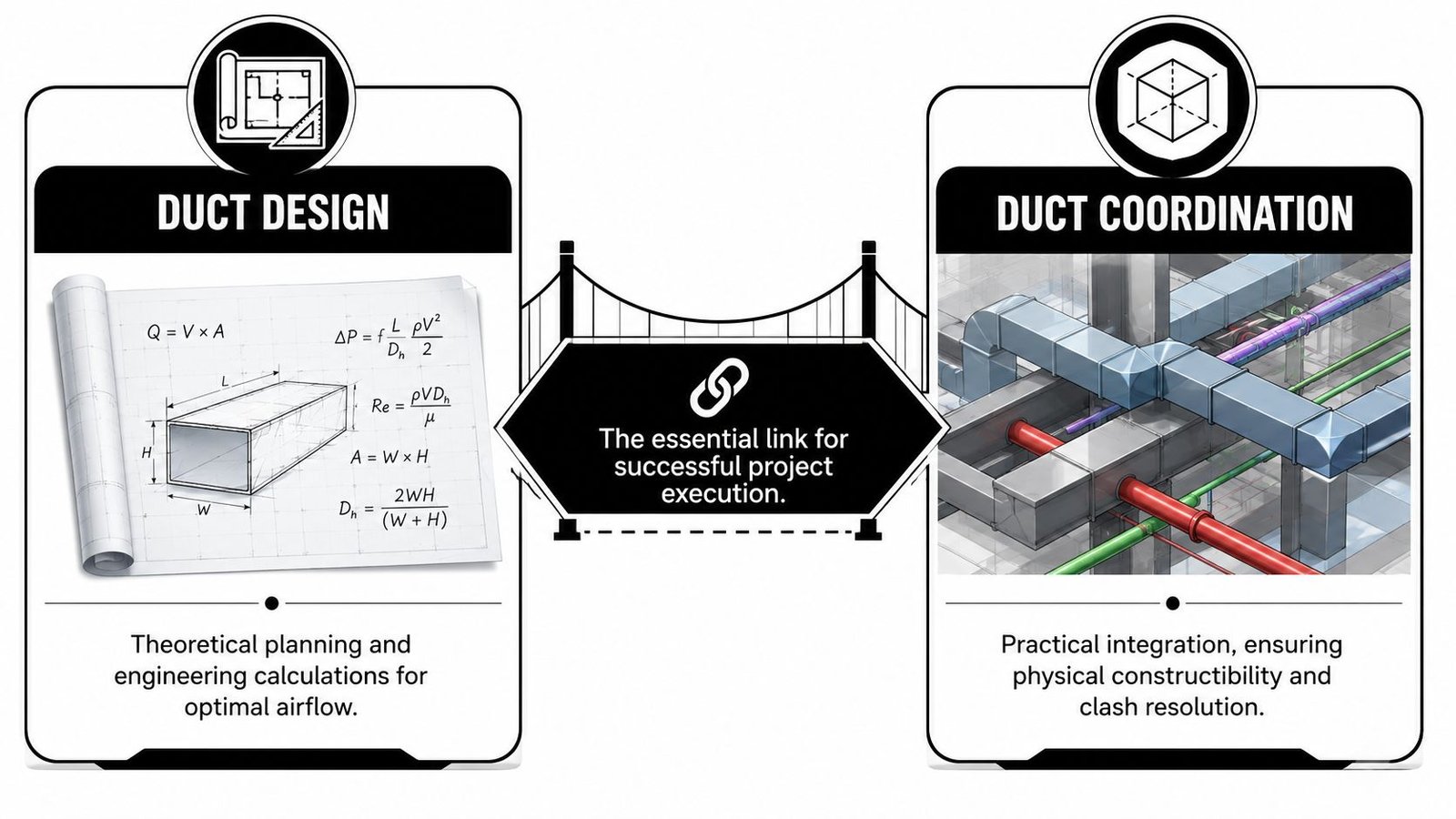
Duct design and duct coordination are related, but they are not the same job. Design answers the performance question. Coordination answers the fit and build question. The projects that run smoothly treat those as two linked decisions, not one blurred handoff.
When teams separate those roles clearly, MEP modeling becomes much more than a visual aid. It becomes the production system that protects margins, reduces RFIs, and gives the project a duct layout that can be built without sacrificing intent.
What Duct Design Actually Covers
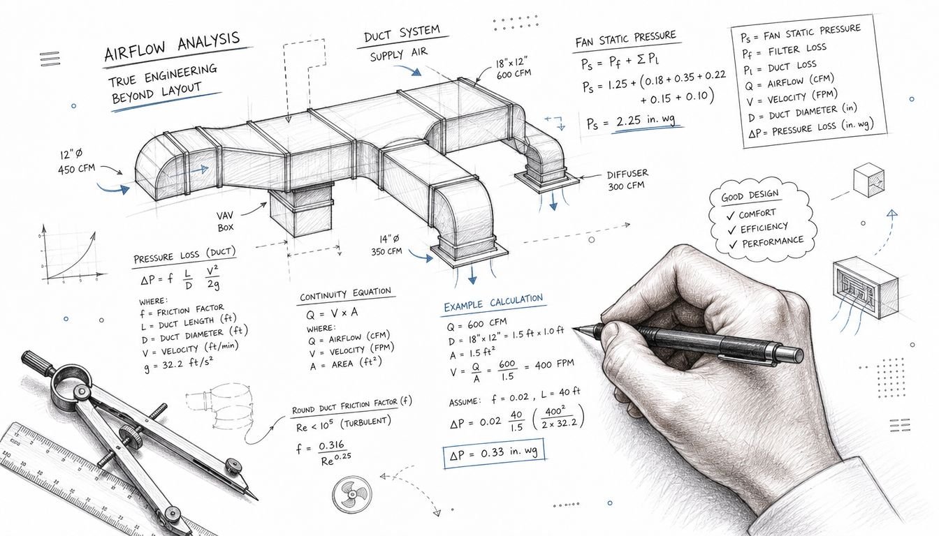
People use duct design as a catch-all term, but in practice it means the engineering side of the work. It deals with airflow, pressure, sizing, noise, and the logic of how air should move through the system before anyone asks whether the route can physically survive a crowded ceiling plenum.
That distinction matters because a duct system can be engineered correctly and still be impossible to install as drawn.
Performance comes first
At the design level, the engineer is making decisions about required air volume, friction loss, branch layout, terminal performance, and the pressure the fan will have to overcome. One commonly used approach is the Equal Friction Method, which maintains a consistent pressure loss of approximately 0.1 inches of water column per 100 feet of duct length across the system, as described by Melink's overview of HVAC ductwork design.
That number isn't the whole story, and it shouldn't be treated as a magic setting. But it illustrates what design is trying to do. It establishes a performance framework so airflow stays balanced and the system avoids obvious waste.
A good engineering layout also considers what happens when the route changes velocity and pressure characteristics. Every elbow, transition, branch takeoff, and return path affects how the system behaves.
Field lesson: If the design team only talks about supply paths and diffuser counts, they're still only halfway through the airflow problem.
Design standards shape the ideal system
In residential work, ACCA Manual D remains the recognized standard for duct design in the US, and ACCA identifies Manual D as the only ANSI standard for residential HVAC duct design. That matters because proper duct design is supposed to come from calculated flow requirements, not installer habit or “what we usually run.”
For coordination teams, the value of understanding this layer is simple. You can't safely reroute what you don't understand. If a modeler moves a main just to clear steel, without understanding why that main was sized and arranged that way, the model may become cleaner while the system becomes weaker.
For a more layout-focused view of how routing intent starts to take shape before trade coordination, this breakdown of an HVAC duct layout drawing is useful context.
What design does not prove
Design does not prove the route is buildable in the actual building. It doesn't confirm that the duct can pass under a beam and over a cable tray. It doesn't resolve a shaft that was dimensioned generously in 2D but shrinks once wall build-ups, structural tolerances, and competing risers show up in the model.
That's where coordination starts.
The Reality of Duct Coordination
Duct coordination is the constructability layer. It takes the engineered intent and tests it against the actual building geometry, the actual trade congestion, and the actual sequence of installation.
Here, clean linework gets humbled fast.
The plenum is a negotiated space
Above-ceiling space isn't empty. It belongs to everyone at once. The mechanical main wants a straight route. The sprinkler main wants elevation priority. Plumbing wants slope. Electrical wants clearance and maintainability. Structure has no interest in moving for any of them.
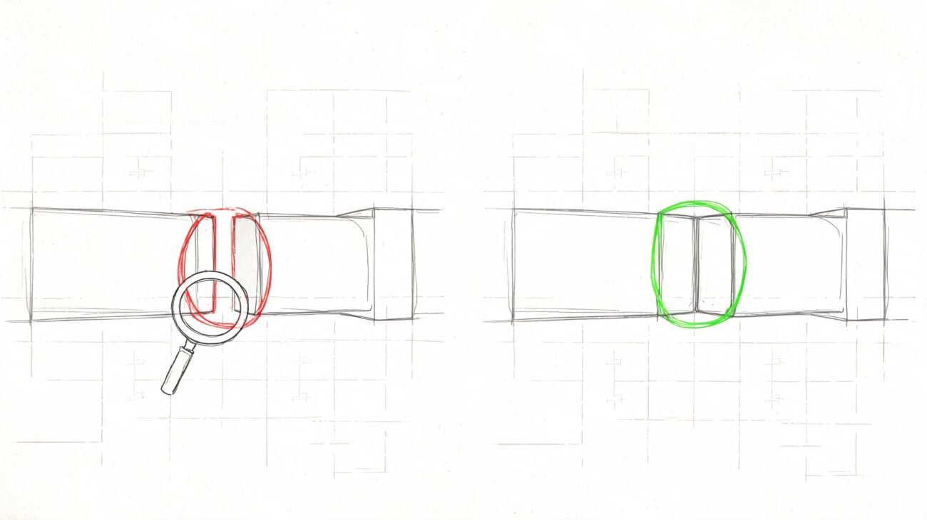
That's why coordination can't be reduced to “run clash detection and fix the red items.” A clash report in Navisworks or Revit is only the starting point. Someone still has to decide which trade moves, how far, and whether that move damages the original design intent.
A mature coordination team asks different questions from the design team:
- Can this main stay at its designed size and still get through the bay without flattening into a bad aspect ratio?
- If the route drops, will ceiling height, access zones, and architectural intent still hold?
- If the fitting count grows, does the reroute still respect the system's pressure and balancing logic?
- If the return shifts, have we created a maintenance problem or a static pressure problem elsewhere?
Coordination is judgment, not software output
The strongest coordination teams don't just detect collisions. They preserve what matters while adjusting what must change.
That takes discipline in the model. Levels have to be right. linked files have to be current. Trade ownership has to be defined. Decision checkpoints have to happen before fabrication packages go out. If that production system is weak, the model becomes a false comfort. It looks coordinated until someone tries to build it.
A duct route that “fits” only after forcing extra offsets into every corridor branch usually isn't coordinated well. It's just been made someone else's field problem.
Good ductwork BIM work creates traceable decisions. You can see why a route changed, what trade took priority, what the revised elevation is, and whether the change still aligns with the engineering basis. That's the difference between a coordination model and a decorative model.
Where Design and Coordination Collide
Most project pain starts in the handoff between engineering intent and constructability reality. Not in theory. In execution.
One common failure looks harmless early on. The engineer lays out a main trunk that works for airflow, the reflected ceiling plan looks clean, and the permit set moves forward. Then the structural model updates. A beam deepens, a transfer condition tightens, and the duct route that looked fine in 2D now runs directly through steel. Nobody catches it until the mechanical contractor starts preparing shop drawings.
The paper-perfect route that won't fit
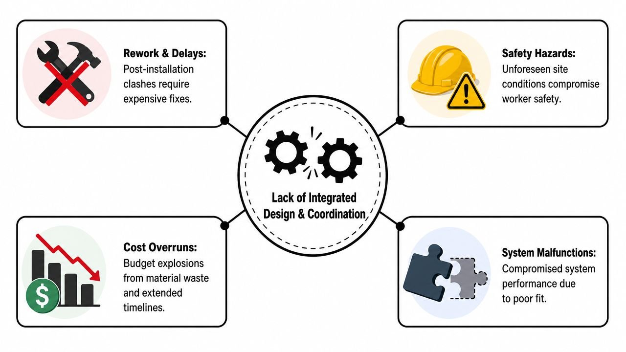
This is the classic “designed but not coordinated” problem. On paper, the duct system performs. In the building, it has nowhere to go without dropping into the ceiling plane or forcing another trade into a reroute.
What happens next is predictable:
- RFIs multiply: The field team needs direction because the contract documents don't resolve the conflict.
- Fabrication pauses: Shop drawing release gets delayed while elevations and offsets are reworked.
- Sequence breaks down: One unresolved main can block follow-on work from multiple trades.
- Responsibility gets blurred: The engineer, GC, and contractors all read the issue through different scopes.
The cost isn't only time. It's loss of rhythm. Once crews lose installation flow, labor efficiency suffers and project teams start making local decisions instead of system decisions.
The late coordination fix that hurts performance
The opposite failure is just as common. Coordination happens late, after the design is treated as locked and procurement pressure is building. The team needs a route to fit quickly, so the duct gets kicked around a beam, necked through a tight zone, and turned repeatedly just to survive the space.
That route may be buildable, but it's no longer faithful to the original engineering.
According to Hi-Tech CADD Services on ductwork design principles, poorly designed, fabricated, and sealed duct systems can reduce overall HVAC efficiency by up to 40%, with losses tied to leakage and excessive static pressure from restrictive fittings. That's the practical consequence of treating coordination as a geometry exercise instead of a performance-sensitive one.
Return air gets hit especially hard in these rushed fixes. As noted in Smart Service's discussion of ductwork design mistakes, undersized or missing return ducts contribute equally to static pressure problems, and return static “matters every bit as much as supply static.” Coordination teams that only protect the supply main while squeezing the return into leftovers are creating a hidden failure.
Coordination warning: The fastest route through a congested zone is often the route that creates the hardest balancing problem later.
This shows up often in low-clearance renovation work. Teams dealing with tight soffits and old framing conditions run into the same kind of constructability pressure found in remodeling basements in Southwest Michigan, where ceiling height, bulkheads, and existing utilities leave very little tolerance for duct routing mistakes. The lesson carries over directly to commercial coordination. Space limits don't care whether the drawing looked reasonable.
How MEP Modeling Delivers Predictable Outcomes
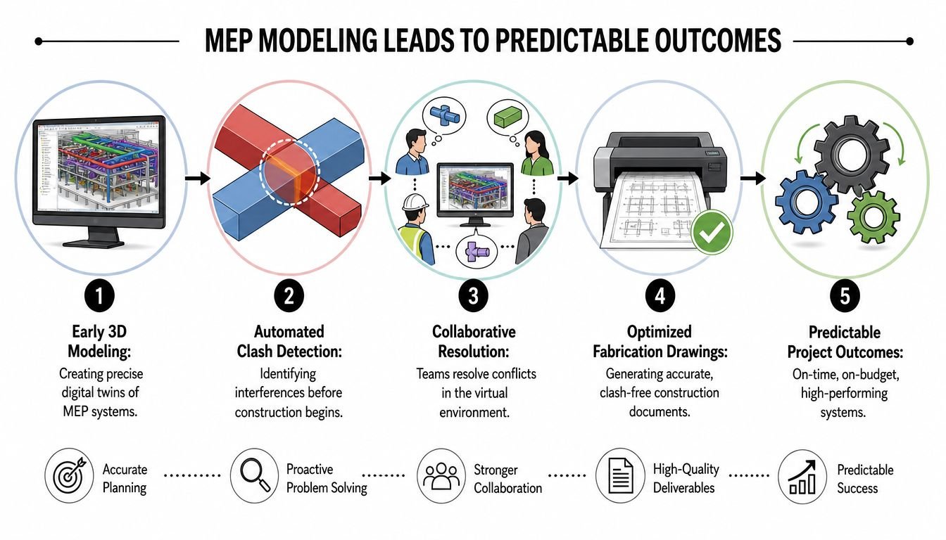
The value of MEP modeling isn't that it creates a nicer picture of the ductwork. It creates a controlled environment for decisions before sheet metal is fabricated and crews are standing under the problem.
That only works when the workflow around the model is mature.
What a mature model catches early
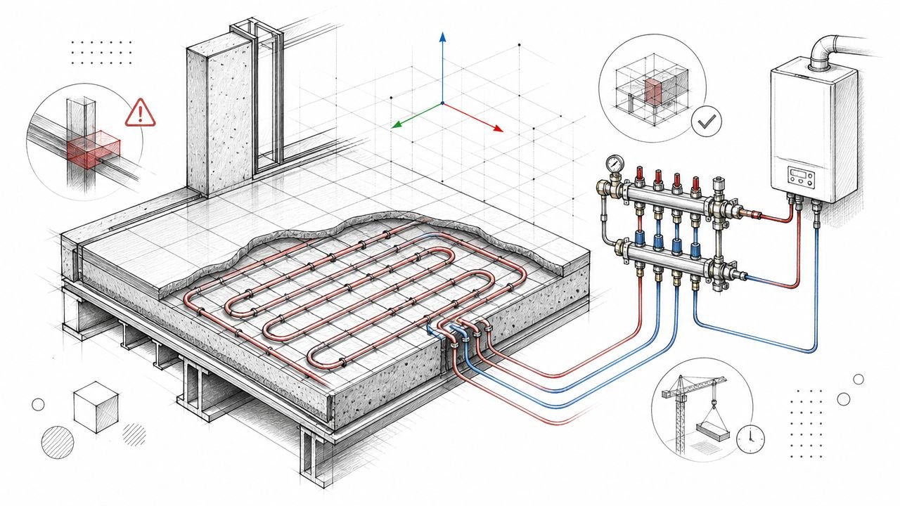
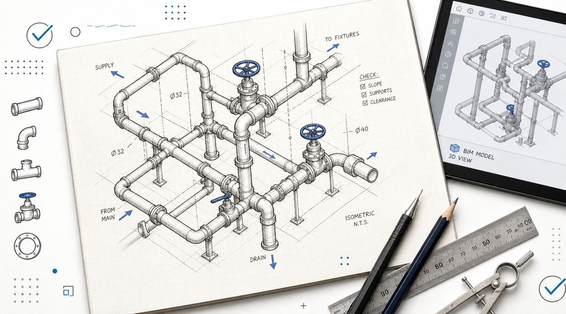
A solid Revit-based workflow exposes conflicts that 2D overlays hide. You see whether the trunk and branch structure fit the available depth. You can test access clearances, shaft crowding, riser continuity, and the knock-on effects of moving one trade on all the others.
That's especially important because duct performance degrades quickly when field improvisation takes over. The Building America guidance from the US Department of Energy notes that residential air distribution systems often operate at only 60–75% efficiency due to undersized, constricted, or poorly installed ductwork, and that duct location and insulation can further reduce effectiveness in unconditioned spaces, as outlined in this duct systems technical report.
The lesson translates beyond residential work. Once geometry starts forcing constrictions and compromises, the system pays for it.
Predictability comes from process discipline
The best teams treat the model as a production system with checkpoints, not a file that gets passed around until deadline. That usually includes:
- Template discipline: Shared content standards for duct families, fitting conventions, elevations, and naming.
- Coordination windows: Planned moments when trade leads review conflicts before downstream drawings are issued.
- QA reviews: Someone checks not just clash status, but whether the “fix” makes sense mechanically.
- Fabrication readiness: The route is vetted before shop details and spool logic lock in.
A service page like this overview of BIM modeling services is a useful reminder that modeling value comes from repeatable production controls, not from software alone.
Why this protects margin
Predictability is margin protection. When the duct route is validated early, crews install from a vetted digital prototype instead of negotiating the building in real time. RFIs drop. Rework drops. Fabrication confidence improves. So does schedule reliability.
That's what people often mean when they say BIM helped. What helped was a disciplined coordination workflow supported by the model.
Clarifying Ownership for Smooth Project Delivery
Projects run better when ownership is explicit. Not broad. Explicit.
The Engineer of Record typically owns duct design. That includes sizing logic, airflow intent, code compliance, and the performance basis of the system. If the route needs to change materially, the EOR needs enough visibility to confirm the revision still supports the original engineering.
Design ownership and coordination ownership are different
Coordination usually sits across several parties. The mechanical contractor brings fabrication and installation reality. The GC or construction manager sets trade priorities and meeting cadence. The MEP modeling team maintains the shared spatial logic, resolves clashes in the model, and documents the agreed path forward.
That division is healthy because the work is different.
| Role | Primary concern | Typical focus |
|---|---|---|
| Engineer of Record | System performance | Airflow, sizing, compliance |
| Mechanical contractor | Means and methods | Buildability, fabrication, install sequence |
| GC or CM | Cross-trade control | Priorities, schedule, issue closure |
| MEP modeling team | Spatial integration | Routing, clash resolution, model quality |
Why dedicated coordination support exists
Engineering teams are often stretched across design development, permit response, submittal review, and owner changes. Coordination demands a different kind of attention. It's iterative, trade-heavy, deadline-sensitive, and detail-driven.
That's one reason firms bring in dedicated support for this layer of work. Not because design is less important, but because duct coordination has to be managed actively and consistently if the project wants predictable output.
A good BIM execution plan helps here because it defines who updates what, when coordination freezes occur, and how model decisions get approved.
Some of the worst duct coordination failures happen on teams where everyone assumes someone else is carrying the constructability review.
There's another reason role clarity matters. Some design assumptions are already under pressure in the field. As discussed by Muller Heating & Cooling in this piece on the hidden cost of poor duct design, friction rates of 0.1 and 0.08 are still commonly expected in residential practice even though they can create excessive static pressure and reduce HVAC efficiency by up to 75% in modern systems. When baseline assumptions are strained, casual handoffs between design and coordination become even riskier.
Unifying Design Intent and Constructability
The distinction is simple, but the consequences are not.
Duct design answers whether the system should perform. Duct coordination answers whether that system will fit, get built, and still perform after real building constraints are applied. Treat those as the same task and the project usually pays twice. First in coordination chaos, then in field rework, balancing trouble, schedule drag, or system complaints after turnover.
The teams that handle this well usually don't rely on heroics. They rely on production maturity. They use consistent templates, current trade models, decision checkpoints, and QA reviews that test both geometry and intent. They don't wait for an RFI to discover that a main trunk shares the same space as a beam pocket. They don't accept a clash-free route if the fix inadvertently destroys return capacity or forces bad fittings into every branch.
That's where Revit MEP ductwork, clash review, and disciplined model management create real value. Not because the software is impressive, but because the workflow prevents preventable mistakes.
If your current process still blurs engineering and coordination into one vague milestone, that's usually the first thing worth fixing.
If you're refining how your team handles duct design, duct coordination, or broader MEP coordination services, explore the deeper resources at BIM Heroes. Their content is useful for teams that want stronger BIM workflows, better decision checkpoints, and more reliable production systems without turning coordination into a constant field rescue exercise.