Meta description: Wall type legends in construction drawings best practices for architects and BIM teams. Learn how to name, place, maintain, and QA wall types to reduce RFIs and keep CD sets clean.
Wall type legends usually fail in boring, predictable ways. Nobody notices at schematic design. Nobody cleans them up at design development. Then framing starts, the contractor tags an inconsistency, and a simple partition question turns into an avoidable RFI chain.
The problem usually isn’t design intent. It’s production discipline. A clean legend tells the field what the wall assembly is, tells the AHJ what rating basis to verify, and tells your own team how to keep the set coherent as walls change across phases. A messy one does the opposite.
For teams producing repeatable CD sets, wall type legends in construction drawings best practices come down to three things: clear scope, controlled naming, and maintenance that survives permit, bid, and CA.
WordPress category: Construction Coordination & Documentation
The RFI That Breaks the Project a Messy Wall Legend
The call usually comes at the worst time. Framing is underway, the superintendent is standing in a room full of studs, and someone asks why the plan tags show PT-7A and PT-7B when the legend only lists PT-1 through PT-5. The PM opens the latest set, the architect opens an older export, and nobody can say with confidence which tag is current.

On small tenant improvements, that’s where things get embarrassing fast. You look at a modest fit-out and somehow the project is carrying dozens of wall types because every height change, soffit condition, backing note, and rated variation got turned into a new tag instead of being managed properly.
That kind of legend sprawl is a documentation failure. Contractors stop trusting the plan tags. Reviewers start hunting for contradictions between the partition legend and life safety sheets. Your own production team burns time figuring out whether a new type should be added, renamed, merged, or ignored.
A wall legend shouldn’t require interpretation by committee.
The expensive part isn’t the drafting time. It’s the disruption. One unclear wall type can trigger RFIs, framing delays, revised details, and field workarounds that never make it back into the record set. Then the as-builts are wrong too.
What usually caused the mess
Most bad legends trace back to the same habits:
- No naming convention: Types are added sequentially with no logic, so the tags stop meaning anything.
- Legends that drift from the model: The plan tags change, but the legend graphic doesn’t.
- Assembly and condition get mixed together: Teams create new wall types for height, head condition, or minor note changes that should’ve stayed instance-based.
- Legend content expands into everything: Details, specifications, firestopping notes, and code language all get shoved into one overloaded graphic.
A reliable legend is a production system, not a sheet decoration. If the system is weak, the RFI is just the first visible symptom.
What a Wall Type Legend Is Actually For
A wall type legend has one job. It communicates the assembly of each wall used in the project. That means the build-up at mid-height, not every possible variation the wall might encounter in the field.
If the legend stays disciplined, the set gets easier to read. If it tries to carry everything, it becomes a dumping ground.
What belongs in the legend
The legend should show the structural core, finish layers, and any performance attributes that are part of the assembly itself. For flexible wall systems using metal studs, specifications often call for minimum steel thickness of 30 mil, spacing no greater than 16 inches on center, and a minimum 5 psf lateral load, as outlined in this overview of wall system requirements. That’s the level of assembly information a good legend is meant to communicate.
In practice, that usually means the legend entry should identify:
- Stud material and size: wood, steel, CMU, concrete, and the nominal stud depth where relevant
- Layer build-up: gypsum board type and thickness on each face
- Cavity content: insulation where it is part of the assembly
- Performance basis: rating and acoustic information when those are assembly-dependent
What doesn’t belong there
A lot of teams overload the legend because they haven’t drawn a clean boundary between documents.
Use this rule set instead:
- Head, jamb, and base conditions belong in details. The legend is not where you explain deflection track, jamb reinforcement, or slab edge transitions.
- Wall height is an instance condition. “To deck,” “to ceiling,” and “partial height” describe placement, not assembly.
- IBC wall classification belongs on life safety sheets. The legend can show the assembly that achieves a rating. It shouldn’t try to replace code analysis language such as fire barrier or smoke partition.
- Product standards and installation requirements belong in specifications. The legend shouldn’t become a substitute for Division 09.
Practical rule: If the information changes when the same wall type is placed in a different location, it probably isn’t legend content.
Why this matters in production
Once teams understand that the legend is an assembly document, a lot of avoidable wall types disappear. You stop creating new entries for every ceiling offset or local condition. You also make the drawings easier to maintain because the legend stays stable while plan notes and details handle the exceptions.
That’s the point. The cleaner the scope, the fewer opportunities you create for contradiction.
A Naming Convention That Prevents Legend Sprawl
Most messy legends don’t start messy. They get there one rushed decision at a time. Someone duplicates a wall type in Revit, renames it quickly, tags it on plan, and moves on. A few deadlines later, the project has a legend full of codes nobody remembers creating.
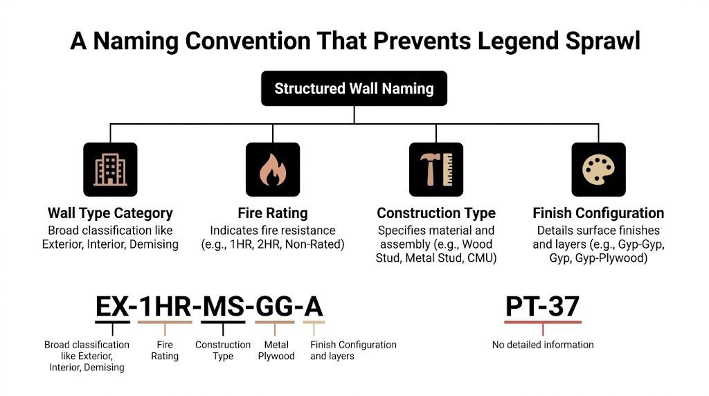
The fix isn’t a cleverer tag. It’s a naming convention that limits what a tag is allowed to communicate.
The two naming systems that break first
The first bad system is pure sequential numbering. You’ve seen it: PT-1, PT-2, PT-3, all the way into nonsense. By the time the team reaches CDs, every tag forces a lookup. The number carries no memory value, no grouping, and no clue about how it relates to nearby types.
The second bad system is composite coding. One tag means assembly, another means condition, and the contractor is expected to combine them mentally. That may feel organized inside the office. In the field, it fails because nobody wants to decode two legends to understand one partition.
What the tag should actually do
A useful wall tag should stay short and stable. It should sort walls into a category that people can recognize immediately, then let the legend do the rest.
A practical office standard looks like this:
| Prefix | Use | Example |
|---|---|---|
| E | Exterior wall assemblies | E1, E2 |
| P | Interior partitions | P1, P2 |
| R | Rated assemblies | R1, R2 |
| S | Shaft or chase walls | S1, S2 |
This structure is intentionally plain. It prevents the tag from trying to hold too much information.
Why hierarchical logic still matters
Architectural documentation often uses hierarchical coding to embed structural information. A code such as FS-90.6 can indicate steel studs at 90mm depth on 600mm centers, as described in this discussion of wall type naming and coding. That logic is useful because it reduces coordination errors when the code is understood across the team.
But there’s a difference between a documentation logic and a field-readable plan tag. On most CD sets, the plan tag should remain simple enough to scan quickly, while the legend entry and type parameters carry the deeper data.
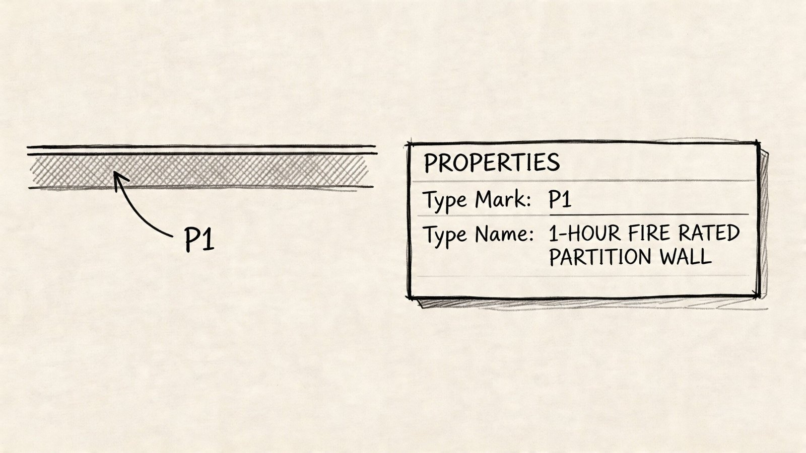
That’s why I prefer a two-layer standard:
- Short Type Mark in plan: P1, R1, E2
- Structured type name in the model: enough detail for production staff to identify the assembly without opening the legend every time
If you need help standardizing that office logic across sheets and tags, this is exactly the kind of drawing consistency addressed in architectural drawing standards.
The field needs readable marks. The model needs disciplined names. Those are related, but they aren’t the same thing.
A workable office framework
Here’s what works in practice.
Keep the Type Mark dumb and the type definition smart
Use Type Mark for the visible tag. Keep it short. Let the type properties, description fields, and legend entry carry the assembly detail.
That protects readability on crowded plans and keeps the tag from changing every time a note changes.
Separate category from variation
A rated wall shouldn’t be buried as “P7X-R”. If it’s a rated assembly, classify it as rated. If it’s a shaft wall, classify it as shaft. Grouping by functional category makes reviews faster and helps your team spot duplication.
Don’t encode instance conditions
Don’t create P1A, P1B, and P1C just because one goes to deck, one stops at ceiling, and one dies into a soffit. That’s how legends bloat. Those are plan conditions, not assembly identities.
Make the Revit parameter match the printed legend
If the legend says R2, the tagged wall on plan should say R2. Not “1 HR Corridor” in one place and “PT-9” in another. Mismatched labels destroy confidence in the set.
What this fixes
A naming convention won’t solve every coordination problem, but it removes a common source of chaos. It also makes review much faster because people can sort walls by category before they even inspect the layer build-up.
That’s the real gain. Better naming doesn’t just clean up the legend. It lowers the chance that somebody frames the wrong wall because the documentation made them guess.
How Many Wall Types Does Your Project Really Need
Most projects need fewer wall types than the set suggests. The gap between those two numbers is where production waste shows up.
The discipline starts with one simple filter: is this a different assembly, or just a different condition? If the answer is “same assembly, different placement,” it should not become a new wall type.
Assembly versus instance
This is the line teams blur constantly. A wall that runs to structure and the same wall that stops at ceiling are still the same wall type if the stud, board layers, insulation, and performance basis are unchanged.
Use plan notes, keyed notes, or details for the instance condition. Don’t multiply legend entries because placement changed.
A good internal rule is this:
- Same stud size
- Same board layers
- Same cavity content
- Same performance basis
If those four stay the same, keep the same wall type.
The variations that do deserve a new type
Some changes alter the assembly itself. Those should become distinct wall types because the contractor is building something materially different.
Examples include:
- Acoustic changes tied to cavity content: If one partition includes insulation and another doesn’t, that’s a different assembly.
- Fire-rated variants: A non-rated partition and a rated version are not interchangeable.
- Exterior cladding systems: A brick veneer wall with an air space is not the same assembly as a direct-applied siding system.
That last point matters in residential and mixed-use work. In U.S. housing, brick accounted for 38% of newly completed homes in 1971, then declined while vinyl siding and fiber cement became more common, according to U.S. residential exterior wall material data summarized here. From a documentation standpoint, those are distinct assemblies and should be treated as distinct legend entries.
A quick decision test
When a new wall type gets proposed, ask these questions before you approve it:
| Question | If yes | If no |
|---|---|---|
| Does the material build-up change? | Create a new type | Keep existing type |
| Does the rating basis change? | Create a new type | Keep existing type |
| Does only the height or termination change? | Note it on plan or in detail | Don’t create a new type |
| Does only the location change? | Reuse the type | Don’t rename it |
If your team can’t explain why a wall is a new assembly in one sentence, it probably isn’t a new wall type.
Start from a standard library
Most firms should begin with a controlled office library of common types. Not every project will use all of them, and some projects will need special additions, but starting from a standard set reduces ad hoc creation.
In practice, that means your typical partitions, rated partitions, shaft walls, and common exterior assemblies already exist in template form. The project team then adds only the exceptions that are project-specific.
Margin protection becomes evident. A team that reuses disciplined wall types spends less time renaming, less time fixing tags, and less time answering basic questions during permit and CA.
The Anatomy of a High-Quality Legend Entry
A strong legend entry is lean, readable, and complete enough to support construction and review. It doesn’t win by containing the most text. It wins by showing the right information in the right format.
When contractors, consultants, and plan reviewers look at the legend, they’re trying to answer a few basic questions fast: what is this wall made of, how thick is it, and what performance is it supposed to achieve?
The graphic needs to do most of the work
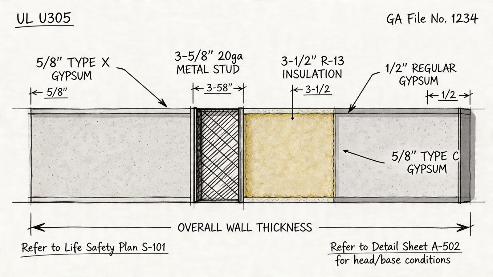
Every wall type entry should include a clear cross-section graphic at a consistent scale. The point isn’t pretty drafting. The point is immediate recognition.
That graphic should show:
- Core structure: metal studs, wood studs, CMU, or concrete with a consistent graphic standard
- Layer sequence: board, sheathing, air space, insulation, finish layers, in the correct order
- Orientation: the same left-right convention across the whole legend
If one entry is drawn tightly, another loosely, and a third at a different scale, the legend becomes harder to scan. Consistency matters more than flourish.
Dimensions should be explicit
You shouldn’t make the reader infer thickness from a hatch pattern. The legend entry should call out the overall wall thickness and the major assembly components.
A useful entry usually identifies:
| Legend field | What it should show |
|---|---|
| Overall thickness | Face-to-face assembly dimension |
| Stud core | Material, nominal depth, and gauge where applicable |
| Board layers | Thickness and type on each side |
| Cavity content | Insulation presence and type where relevant |
This is also where supporting technical content can help teams detail assemblies consistently. For example, projects using steel stud partitions often need coordination with framing standards such as those discussed in metal stud frame guidance.
Put performance data next to the graphic
Burying fire and acoustic information in a note block is a bad habit. Put that information in a compact tabular zone beside the section graphic so it can be scanned immediately.
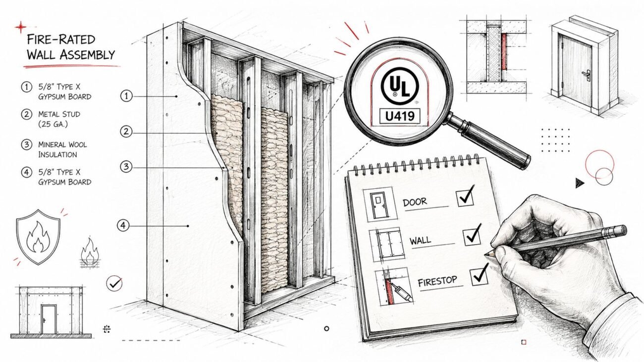
For rated walls, include the rating basis. In practice, that means the relevant assembly reference should be shown in the legend entry, while the underlying library or listing can be checked against a source such as the UL fire resistance directory.
A compact performance area might include:
- Fire rating
- Assembly reference
- Acoustic notation if required
- Insulation indicator
Field note: If the AHJ has to hunt for the rating basis, you’ve already made review harder than it needs to be.
Cross-reference the rest of the set
A wall type legend should not stand alone like an orphaned diagram. If a wall has a typical head condition, reference the applicable detail. If rated walls are identified by location on life safety drawings, the legend should connect to that sheet set.
Walls are constructed through the assembly of multiple documents. The legend identifies the assembly. The plan locates it. The detail resolves the condition. The specs govern execution. If those connections aren’t visible, the team starts filling in gaps by assumption.
What to leave out
A lot of legends get bloated because nobody says no to extra content. Keep these items out of the entry itself unless a specific jurisdiction or office standard requires otherwise:
- Seismic tie and bracing notes
- Firestopping at penetrations
- Manufacturer-specific substitutions
- Long-form installation instructions
- General specification language
Those items belong elsewhere in the set. The more you cram into the legend, the more brittle it becomes when revisions happen.
A high-quality legend entry gives the field enough to build the correct assembly and enough to find the next document without confusion. That’s all it needs to do.
Where the Legend Lives in Your Drawing Set
Legend placement looks like a sheet organization question, but it’s really an access question. If the field can’t find the wall assembly information quickly, the legend might as well not exist.
First plan sheet versus general sheet
On smaller projects, putting the wall legend on the first floor plan sheet is often the most useful option. The contractor is already there, and the legend is one page turn away from the plan tags being read.
On larger projects, teams often move it to a dedicated general sheet. That can work well inside the office because legends, abbreviations, and keynote information stay grouped. The problem is that field crews don’t always live in the general sheets once work starts.
Here’s the practical trade-off:
| Placement option | Strength | Risk |
|---|---|---|
| First floor plan sheet | Easy for contractors to access | Space can get tight |
| Dedicated general sheet | Cleaner sheet organization | Easier for field crews to lose track of |
| Dedicated legends sheet plus reduced references on plans | Best balance for larger projects | Requires discipline to maintain both |
What works best on multi-story projects
For multi-level work, the hybrid approach usually performs best. Keep the full graphic legend on a dedicated legends or general information sheet. Then place a reduced wall assembly legend CD set reference on each floor plan sheet with just the type mark and key attribute cues.
That way the framer or reviewer can verify a tag quickly without hunting through the entire set, while still having a full source document to check when needed.
What to avoid
Don’t bury the wall legend only in the specs. Don’t assume the field will open a model viewer to answer a framing question. And don’t hide the only usable legend on a sheet nobody prints.
A wall legend has to be plottable, accessible, and easy to locate. If your sheet organization makes that difficult, the issue isn’t user behavior. It’s the set.
Maintaining the Legend Through the Project Lifecycle
A wall legend is never “done” at the moment it first looks clean. It stays accurate only if the team treats it as a live production item through every issuance.
Build it from the model, not from static drafting
If the legend is assembled from pasted details, copied drafting views, or screenshot graphics, drift is almost guaranteed. The wall type changes in Revit, but the legend stays frozen. Then the tags and the legend stop matching.
Legend Component views are the safer path because they reflect actual modeled wall types. That doesn’t solve everything by itself, but it removes one common source of mismatch.
Add a wall legend QA step to every issuance
Before permit, bid, addendum, or conformed issue, run an explicit legend check. Not a casual glance. A real check against the model and tagged plans.
That review should answer:
- Are all tagged wall types present in the legend?
- Are any legend entries unused and ready to be removed?
- Do rated wall references still align with the current set?
- Did any accepted design changes alter assembly definitions?
A clean legend at 50 percent CDs means nothing if nobody verifies it before permit.
Treat CA changes as documentation changes
A lot of teams fall apart when, during CA, substitutions get accepted, rated assemblies get revised, and field conditions trigger changes. If those changes never make it back into the legend or clearly into the record trail, the project starts carrying two truths: what was issued and what was built.
Accepted changes should be documented in one of two ways:
- Revise the legend formally, if the accepted change alters the assembly definition.
- Reference the approved variation clearly in the RFI or submittal trail, if the original type mark remains but a controlled exception is approved.
The point is traceability. When somebody comes back later asking what wall was intended, the answer should exist in the record without detective work.
Why this is a margin issue
Maintaining wall types isn’t admin overhead. It protects the job from avoidable confusion and keeps the as-built record usable. That’s especially important when multiple production staff touch the model over time, or when outside teams support delivery and need a stable standard to work from.
Revit-Specific Production Notes for Your Team
Revit can either stabilize your wall legend workflow or make the mess harder to untangle. The difference comes down to how your team uses parameters and view types.
Set up the model so the tag stays clean
Use the Type Mark parameter for the visible wall tag. That’s where P1, R1, E2, and similar marks belong. Don’t use the full type name in the tag. Plans get cluttered fast, and long names break readability.
Store the deeper data somewhere else in the type properties. Assembly description, comments, and controlled naming fields are better places for technical references and internal production detail.
Build legends from live components
Use Legend Components, not drafting views. If the wall type changes, the legend needs to reflect that change with as little manual handling as possible.
That also helps when your office is standardizing templates, type libraries, and reusable production content. Teams doing that work often pair office standards with family and content governance such as creating Revit families, because wall types and annotation standards usually break together, not separately.
Purge and control before issuing
Unused wall types are dangerous because they look legitimate. If they survive in the file, they can show up in legends, schedules, or tags at exactly the wrong time.
Before issuing:
- Purge unused wall types
- Verify Type Mark uniqueness
- Check that legend entries match placed walls
- Confirm rated walls display clearly on plans where required
Revit discipline matters even more on irregular conditions. Non-orthogonal walls such as sloped walls in attics can reduce usable headroom by 20-30%, as noted in this discussion of sloped wall conditions. Clear, parametric wall type standards give teams a stable baseline so those exceptions don’t corrupt the rest of the documentation.
One note on tools and support
For firms trying to formalize template discipline across repeated projects, production partners can help standardize wall libraries, tags, and legends. BIM Heroes does that kind of architectural production and BIM coordination work as one delivery option among others, especially for teams trying to clean up inherited CAD-to-BIM habits.
From Messy Legends to Predictable Production
A clean wall legend is one of those small signals that tells you whether a firm has real production maturity. If contractors can read your tags, find the assembly, and move on without a clarification call, the documents are doing their job. If they can’t, the job starts absorbing confusion as cost.
The same is true in review. When rated assemblies are easy to verify and the legend aligns with the rest of the set, plan review gets simpler. When the wall types, life safety information, and details contradict each other, everyone slows down.
The fix isn’t glamorous. Define the legend’s scope. Use a naming convention that doesn’t collapse under pressure. Keep assembly decisions separate from instance conditions. Maintain the legend through every issue set like it matters, because it does.
Firms that do this well usually aren’t producing prettier drawings. They’re producing more predictable ones. That difference protects time, reduces avoidable RFIs, and gives delivery teams a more stable way to scale.
If your team is dealing with inherited wall standards, inconsistent Revit tags, or legends that drift every time the project changes, a practical next step is to compare your current process against a repeatable production standard. BIM Heroes helps AEC teams build that kind of documentation discipline with structured BIM workflows, architectural production support, and scalable CD set systems.