Meta description: Revit view range controls far more than a cut height. Learn how top, cut, bottom, and view depth affect plan accuracy, coordination, and documentation quality in live Revit projects.
Category: BIM Technology & Workflows
A floor plan goes out for review and something feels off. A window is missing. A door looks wrong in plan. A low partition disappears in one room but shows in another. The first reaction is usually familiar. Check Visibility/Graphics. Check the workset. Check phase filters. Check whether someone changed the family. Then, after too much time spent chasing the wrong problem, the issue turns out to be Revit view range.
That pattern shows up constantly in production. The dangerous part is that view range errors don’t always look like view range errors. They look like model inconsistency, annotation mistakes, linked-model issues, or user error. On live projects, that confusion costs review time and creates avoidable RFIs because the plan no longer matches what the model intends to communicate.
Teams that produce reliable CDs don’t treat view range as a setup checkbox. They treat it as a documentation control. Revit introduced View Range in Revit 6.0 in 2005, and early pre-release survey data tied uncontrolled projections to visibility errors in up to 40% of floor plans (ATG USA on Revit View Range). That’s why experienced BIM staff check it early, not after everything else fails.
Introduction
A junior technician usually finds view range the hard way. The model is clean, the family is loaded correctly, the linked file is visible, and the phase is right. But the plan still lies.
One common example is a clerestory window that won’t show where the architect expects it. Another is a millwork-heavy apartment plan where counters and low partitions read inconsistently from room to room. The worst cases are the subtle ones: a plan that looks complete enough to pass a quick internal review, then creates confusion in permitting or field coordination because what is shown as cut should have been projected, or shouldn’t have been visible at all.
That’s why Revit plan view accuracy depends heavily on understanding view range as a system, not a single setting. If you’re producing floor plans, enlarged plans, coordination views, or permit drawings, this is one of the places where production maturity shows up fast.
Good teams don’t just make plans look right. They know why the elements are appearing the way they are.
The Four Planes That Define Revit View Range
Revit view range is a vertical slice through the model. It is not just a cut height. Revit uses four horizontal planes together to decide what appears in plan and how it appears.
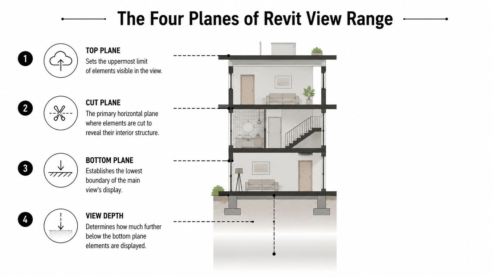
Top plane
The Top Plane is the upper limit of the primary range. Elements above it are outside the main view slice. If the geometry sits entirely above this plane, it won’t behave like an object within the plan’s normal visible range.
Cut plane
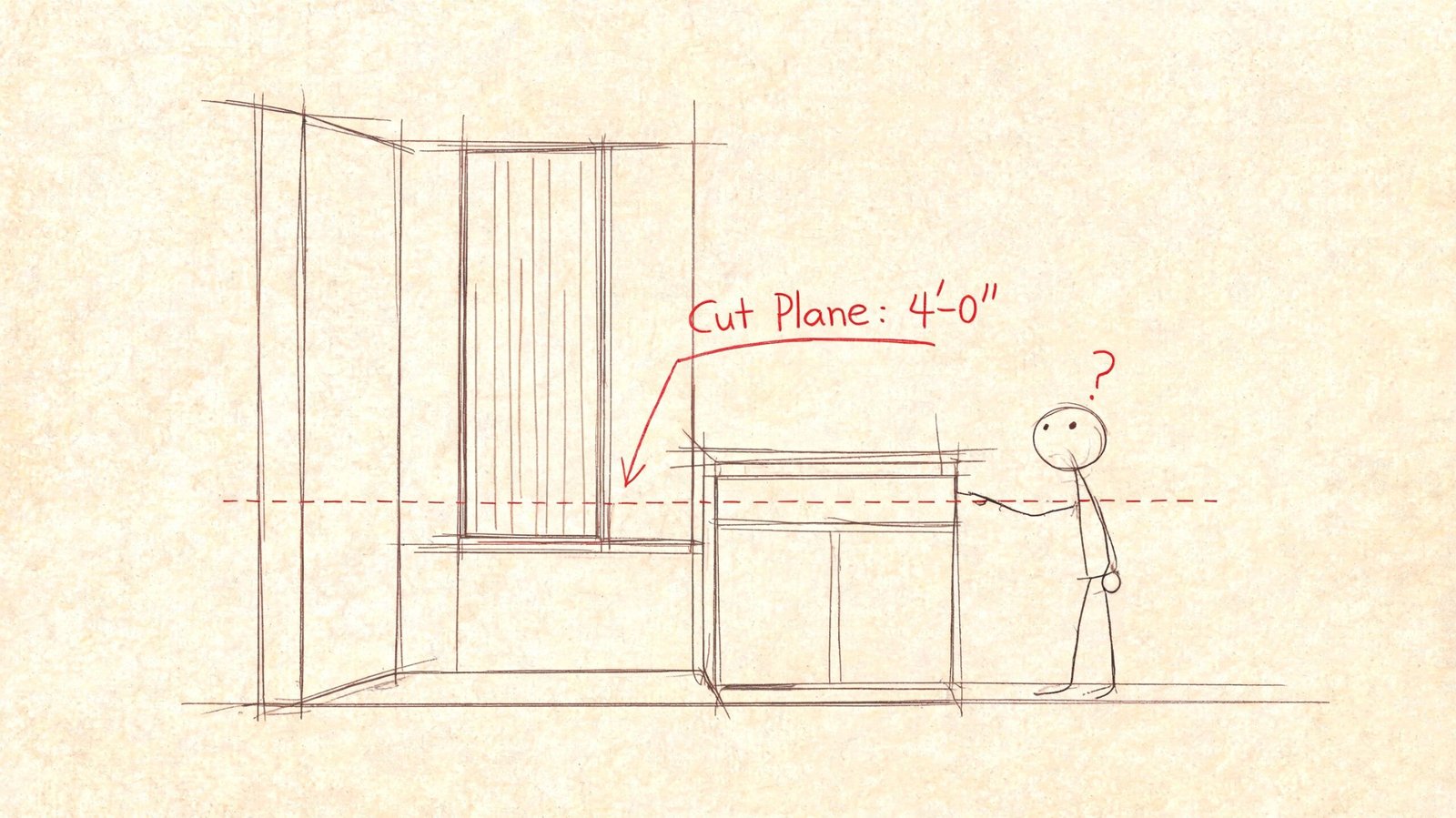
The Cut Plane is the most important of the four. It is the horizontal plane where Revit cuts through model geometry to create the familiar plan representation. Autodesk-based guidance commonly places this around 4 feet (1.22 m) above the level by default for floor plans, which is why walls, doors, and many windows display the way users expect in standard plans.
Bottom plane
The Bottom Plane sets the lower edge of the primary range. Geometry between the cut plane and bottom plane is generally shown in projection rather than cut. That distinction matters because projected elements read differently, especially when lineweights are set up properly.
View depth
The View Depth extends the view farther downward. Elements in this lower extension can display using the line style rather than the normal cut or projection style. At this point, recessed slabs, footings, trenches, and below-floor conditions start to enter the conversation.
A useful way to think about it is this:
| Plane | What it controls | Common failure when wrong |
|---|---|---|
| Top | Upper visible limit | Tall elements vanish or truncate |
| Cut | Where objects are cut | Doors, windows, walls, and casework read incorrectly |
| Bottom | Lower edge of primary range | Low objects show in projection when cut was expected |
| View Depth | Extra range below bottom | Below-floor items clutter plans or disappear |
If you only adjust one plane without understanding the others, the plan may improve in one area and break in another.
Why the Cut Plane Is Your Most Critical Setting
The Revit cut plane is where most documentation mistakes start. It’s also where many users stop thinking after they see the default value and assume it should remain untouched.
A 2023 Dodge Data & Analytics finding summarized by BIM Associates states that improper Revit View Range settings contribute to 52% of all plan view visibility overrides and lead to an average 22% increase in modeling rework hours for mid-sized AEC firms. That tracks with what production teams see in practice. A bad cut plane creates recurring cleanup work because people keep solving the symptom instead of the cause.
Where the default cut plane fails
A standard floor plan cut around 4 feet works well for many ordinary wall-and-door conditions. It starts failing when the plan includes geometry that doesn’t live in that conventional slice.
- Clerestory windows: If the sill is above the cut plane, the window won’t display as a cut opening. Depending on the rest of the view range, it may show in projection or disappear from the floor plan entirely.
- Low partitions and casework: A 3-foot-6-inch partition, reception desk, or countertop sits below the cut plane. It will read as projected, not cut. In a dense plan, that can make it look secondary or even accidental.
- Sloped geometry: Ramps and sloped floors intersect the cut plane at specific points, not across their full extents. The plan representation can feel displaced if you’re expecting a flat-element behavior.
- Split-level rooms: In split-level houses and mezzanine conditions, one global cut plane often produces incomplete or misleading room-to-room representation.
What to check in live production
When a plan looks wrong, review the element’s actual height and compare it to the cut plane before touching Visibility/Graphics overrides.
Use this quick check:
- Identify the element’s vertical limits. Look at sill height, top constraint, family geometry, or instance elevation.
- Check whether the cut plane intersects it. If not, Revit cannot show it as a cut condition.
- Ask what the drawing is supposed to communicate. A permit plan, enlarged restroom plan, and furniture-heavy sales plan may need different cut logic.
- Adjust the view deliberately. Don’t force the family or override graphics unless the view range logic is already correct.
Practical rule: If a user keeps applying linework or category overrides to “fix” a stubborn plan element, the cut plane probably hasn’t been resolved.
What works and what doesn’t
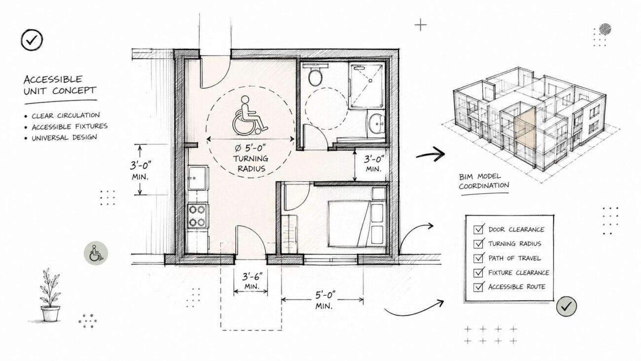
What works is setting Revit view range settings based on the purpose of the view. Enlarged plans often need different cut logic than overall floor plans. Unit plans, kitchen plans, and accessibility details frequently do too.
What doesn’t work is leaving every plan at the same default and patching exceptions manually. That creates inconsistency between sheets, makes QA harder, and turns every late-stage revision into a search exercise.
How the Top Clip Silently Excludes Model Elements
The top clip causes a different kind of problem. It doesn’t create an odd-looking representation. It directly removes things from the plan with very little warning.
That’s why top clip issues are easy to misdiagnose. A user sees a missing rooftop penetration, a truncated tall casework element, or a structural member that appears in section but not in plan. They start checking categories, filters, linked view settings, and family visibility. Meanwhile, the geometry is sitting above the top of the view range.
Common silent failures
On upper levels, this often appears with roof-adjacent elements. A parapet return, rooftop unit, or penetration may belong to the way the team wants to document the roof plan, but if the top clip stops short, those items don’t appear.
In interior work, tall equipment can trigger the same issue. A specialty cabinet, vertical chase, or mechanical element may rise beyond the top clip and disappear from the plan representation unexpectedly.
Structural coordination can get even messier. A column may extend correctly through multiple levels in 3D and section, but in one floor plan it appears to stop because the plan’s vertical slice doesn’t include the upper portion users expect to see. If you’re also troubleshooting cut graphics, it helps to understand how Revit Cut Geometry works in related situations.
A better diagnostic habit
When an element should clearly be visible in plan and the usual visibility checks come back clean, ask one simple question: is the geometry inside the top of the view range?
Missing elements with correct category visibility often point to range, not visibility.
That question saves time because top clip problems rarely announce themselves through obvious warnings. They just leave holes in the drawing set.
Controlling Below-Floor Elements with Bottom and View Depth
The lower half of view range is where plan legibility often gets lost. Users know they need to “show something below,” so they deepen the range until the element appears. Then the plan fills up with items that never belonged there.
The Bottom Plane and View Depth are not the same thing. Bottom controls the lower edge of the primary range. View Depth extends farther down and can display elements with the line style.
Why the distinction matters
Elements in the primary range and elements beyond it should not read the same way. If they do, the drawing starts mixing cut information and below-floor context with no visual hierarchy.
That’s why object style setup matters. A projected countertop, a recessed slab edge, and a footing below the floor shouldn’t compete visually with cut walls and doors.
Common production problems
- Foundation clutter in architectural plans: If the view depth goes too deep, footings or grade beams can bleed into a first-floor plan and create noise that belongs in a foundation or structural view.
- Missed recessed conditions: If the depth is too shallow, trenches, depressed slabs, and below-finish-floor conditions don’t appear when they need to.
- Projected items reading like cut items: If the style isn’t visibly lighter, reviewers can mistake a projected low element for a cut condition.
A practical office standard is to make the Beyond style clearly lighter than cut lines so anyone reviewing the sheet can read the difference immediately. That’s a small template decision with a big QA payoff.
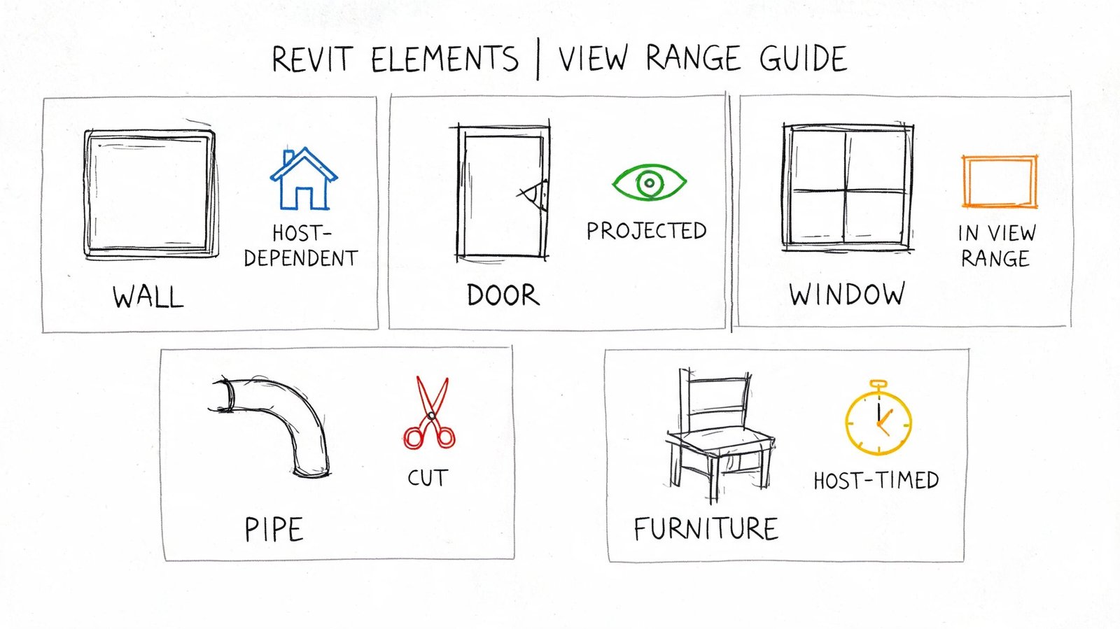
View Range Behavior with Different Element Categories
Many working users get tripped up because Revit plan view behavior isn’t perfectly uniform across categories. Two elements at similar heights can still display differently because their category logic and family geometry are not identical.
Microsol notes that Revit includes built-in exceptions for floors, stairs, and ramps, using an adjusted range that extends 4 feet below the Bottom Plane so those elements remain visible even when they dip below the primary range (Microsol on Revit View Range behavior). If you don’t know that exception exists, some stair and slab behavior looks inconsistent when it’s native Revit logic.
Walls and windows
Walls are straightforward until heights vary. If the cut plane intersects the wall, you get a cut wall. If the wall top is below the cut plane, it may only project. In multi-height interiors, that can leave one room showing a full bold wall cut while the adjacent low partition reads lighter and thinner.
Windows are less forgiving. If the cut plane doesn’t intersect the opening geometry, they won’t present as a cut opening in the way many users expect. That’s why high sill windows and clerestories create so much confusion in plan.
Stairs and ramps
Stairs depend on both view range and stair display logic. If the cut plane misses the expected stair cut location, the stair can look incomplete or incorrect for plan communication. Ramps bring the same challenge in a different form because their slope changes where the geometry intersects the slice.
Stair problems are often range problems wearing the disguise of annotation problems.
Ceilings and overhead conditions
Ceilings surprise newer production staff because they often expect floor plans to reveal them automatically. They don’t. If the ceiling sits above the active floor plan range, it won’t appear there by default. That behavior is correct, but it means teams need separate reflected ceiling plan logic instead of trying to make one floor plan do every job.
Structural framing and coordination views
Structural framing is another category where teams lose time. If the framing lives above the top of the host floor plan range, it may not appear even though everyone knows it exists in the model. In linked-model coordination, that can look like a link issue when the issue is a host view problem.
A useful troubleshooting habit is to stop asking “why won’t this category show?” and start asking “how does this category behave when this exact geometry intersects this exact range?” That shift makes Revit documentation accuracy much easier to control.
Resolving View Range Issues in Linked Models
Linked models add one more layer of confusion because users often assume the linked file’s own views control what they see. For plan visibility, that assumption causes a lot of wasted time.
The key rule is simple. Linked model elements obey the host view’s view range, not the view range from a view inside the linked model.
That’s why a structural engineer can have perfectly correct framing views in their own file while the architect sees missing or inconsistent elements in a host coordination plan. The architect’s plan is applying its own vertical slice to the linked geometry.
A quick coordination check
When linked elements look wrong in a plan, check these in order:
- Host view range first. Confirm the host cut, top, bottom, and depth capture the linked geometry.
- Then review display settings. Linked view settings matter, but they don’t replace host range behavior.
- Check worksharing assumptions. If the team starts blaming visibility ownership too early, it helps to revisit how worksets affect Revit coordination workflows.
The goal isn’t to force every consultant to use matching view ranges. Different disciplines need different documentation logic. The goal is to understand which file is in control of the coordinated view you are issuing.
Using Plan Regions for View Range Exceptions
Plan Regions are one of the best tools in Revit when used surgically and one of the worst habits in Revit when used as a patch for a bad base view.
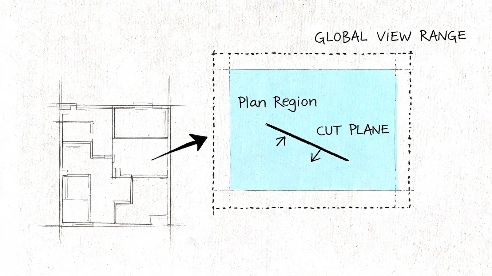
A plan region lets part of one plan have a different view range from the rest of the view. That makes it useful in conditions where the building itself changes height logic locally.
Good uses for plan regions
A mezzanine overlooking a lower level is a strong use case. So is a sunken living room, a raised platform, or an area where a local condition needs a different cut behavior than the rest of the floor.
Enlarged plans can benefit too. In a restroom or kitchen area, a local region may help show fixtures or low-height elements correctly without rewriting the entire floor plan’s view range logic.
Bad uses for plan regions
If most of the floor needs the same adjustment, the global Revit floor plan settings are wrong. Fix the view. Don’t draw a collection of plan regions across half the project just to avoid making a proper template decision.
That’s the fundamental trade-off. Plan Regions are excellent for local exceptions. They are poor substitutes for office standards, view templates, and disciplined setup.
Mastering View Range for Production Excellence
Revit view range affects what your plans show, what they hide, and how every visible element is represented. That makes it a documentation tool, not a background property.
When it’s set poorly, teams chase the wrong problems. They override graphics, edit families, question links, and spend review time on symptoms. When it’s set deliberately, plans become more predictable, coordination improves, and QA has fewer surprises. If your team is standardizing plan behavior across templates, it also helps to tighten Revit view template strategy.
Production teams usually earn their reliability in settings like this. Not because the setting is glamorous, but because it decides whether the drawing tells the truth.
If your team keeps running into floor plans with missing, unexpected, or misleading elements, BIM Heroes can help diagnose the production issue behind the symptom. We regularly review view setup, template logic, and documentation workflows for firms that need more predictable Revit output. If useful, start with a conversation about your current plan standards, QA checks, or coordination pain points.