Meta description: Point cloud accuracy is not the same as project accuracy. Learn where point cloud scan data fails, how scan to BIM workflows go wrong, and what to verify before modeling.
A renovation team designed against a point cloud that appeared to show a flat slab. The cloud looked clean. The sections looked believable. The model followed it closely.
Then construction started, and the field team found a consistent slope the design hadn’t accounted for. The scanner hadn’t captured the actual floor condition because the area was covered with stored equipment during the scan. The point cloud wasn’t wrong in the conventional understanding of “wrong.” It was incomplete, and the project treated incomplete data as ground truth.
That’s the hidden risk in a point cloud scan. The data looks precise, so teams assume it’s complete, current, and reliable everywhere. It isn’t. Point cloud accuracy is powerful, but it still depends on visibility, registration, timing, material behavior, and modeling judgment. If your team uses scan data for renovation design, coordination, permitting prep, or as-built documentation, the actual job isn’t just getting the cloud. It’s knowing where that cloud can support decisions and where it needs verification.
The Hidden Risk of Trusting a Point Cloud Scan
Most project failures tied to scan data don’t start with bad technology. They start with a bad assumption.
The assumption is simple. If the scanner is accurate, the model built from it must also be accurate. That sounds reasonable until the project reaches a condition the scanner couldn’t fully see, the modeler had to interpret, or the field changed after capture. Then the error shows up where it hurts: RFIs, rework, missed clearances, fabrication issues, and late design corrections.
Why this keeps happening
Modern systems are impressive enough to create false confidence. Trimble documented laser scanning at 500,000 points per second with accuracy within approximately 2mm under ideal conditions. That level of detail is a major leap from older methods that produced much lower density. It also makes the output look more complete than it really is.
Field lesson: Dense data is not the same as complete data.
A cloud can look authoritative and still hide missing slab edges, blocked penetrations, concealed steel, or outdated conditions. That’s why over-trusting point cloud accuracy creates a specific class of downstream failures. The issue isn’t whether scanning works. It does. The issue is whether the team understands the limits of what was captured.
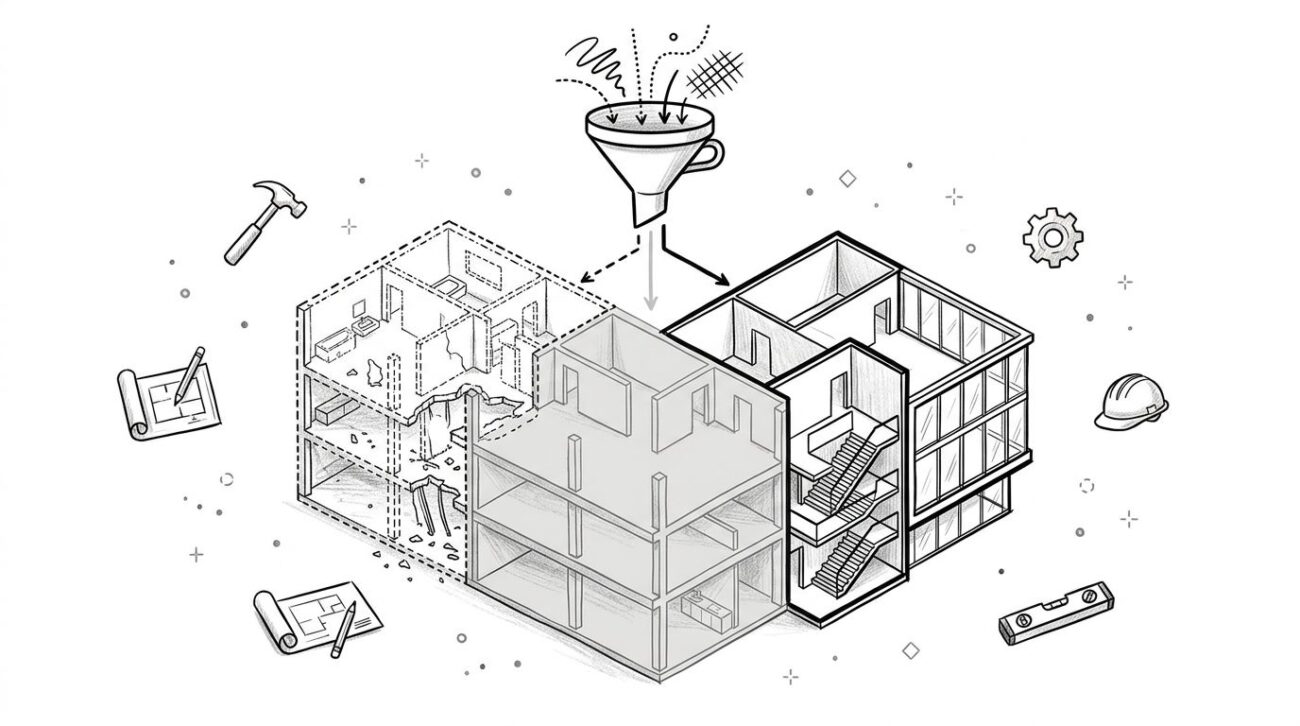
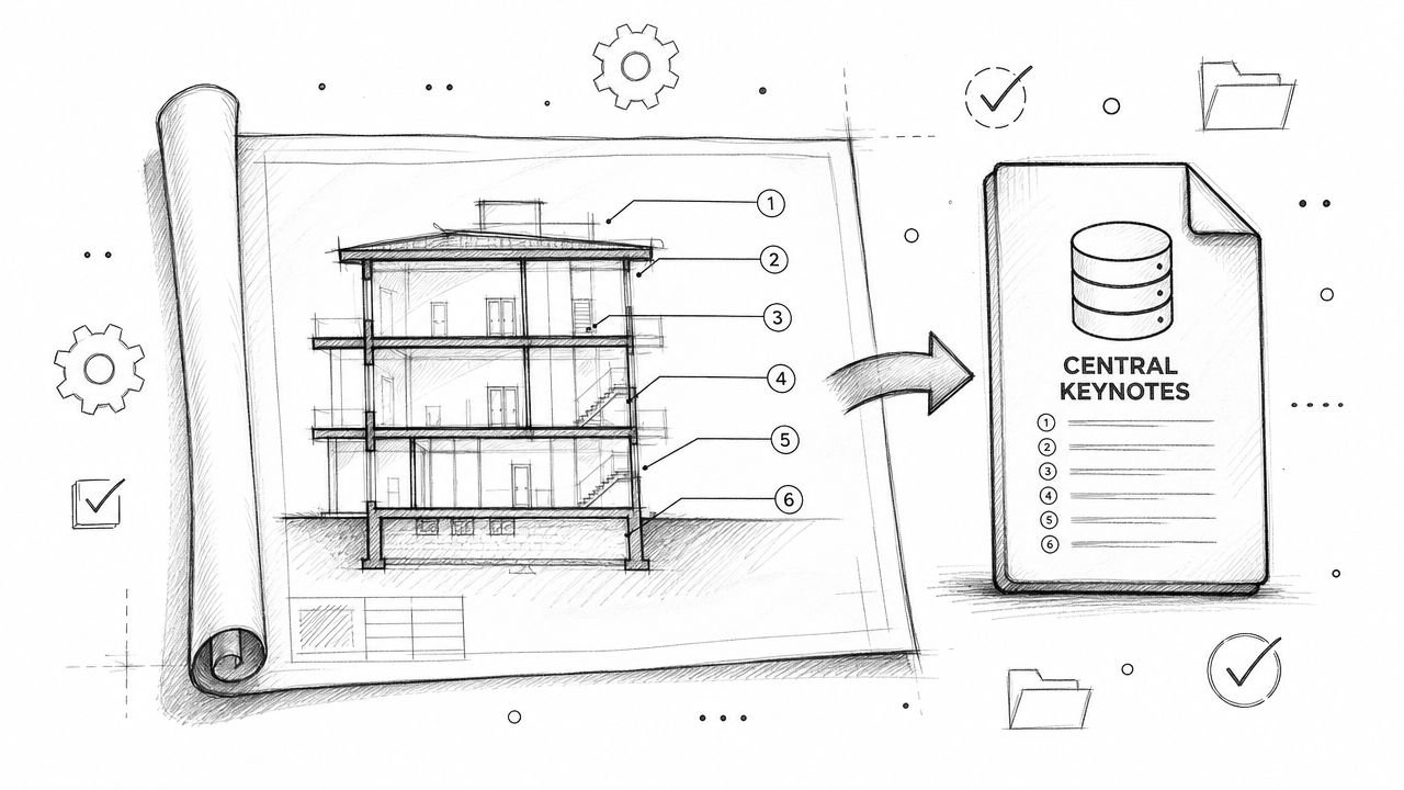
What a Point Cloud Is And What It Is Not
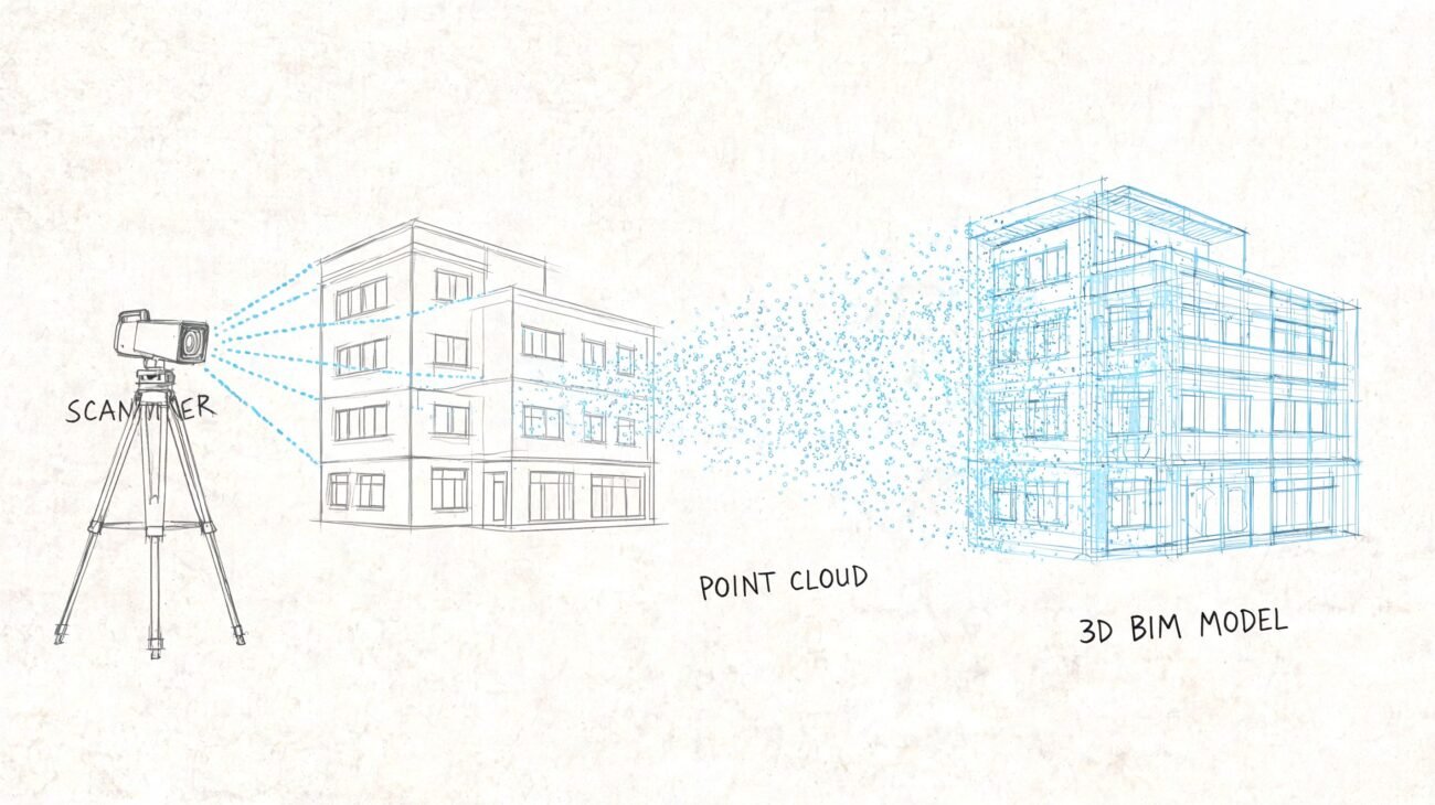
A point cloud is a collection of discrete XYZ coordinates captured from surfaces the scanner could reach. Many datasets also include RGB color information and intensity values, which help teams read surfaces and distinguish elements during processing and modeling. But those points are still only points. They are not a wall object, a floor assembly, a beam family, or a coordinated BIM model.
That distinction matters because project teams often talk about the cloud as if it were a finished record of reality. It isn’t.
What it is
A point cloud is:
- Positional data captured from visible surfaces
- Momentary data tied to a specific date and site condition
- Line-of-sight data limited by where the scanner sat and what blocked it
What it is not
A point cloud is not:
- A continuous surface with no gaps
- A digital twin by default
- A permanent record of existing conditions
- A coordinated model ready for design decisions
The industry has moved far beyond manual stereo compilation and sparse field capture. Point cloud generation now comes from multiple methods, including LiDAR, photogrammetry, Semi-Global Matching, and Structure from Motion. LiDAR Magazine’s overview of the evolution of point cloud workflows is useful here because it makes the key point clear: point clouds are produced through different capture methods and then aligned into a common coordinate system. That alignment step is part of the product, not an administrative afterthought.
A point cloud records what the scanner could see from the positions it occupied at that moment in time. Nothing more.
Once a team understands that, the rest of the scan to BIM workflow gets sharper. You stop asking, “Do we have a scan?” and start asking, “What exactly did this scan capture well enough to trust?”
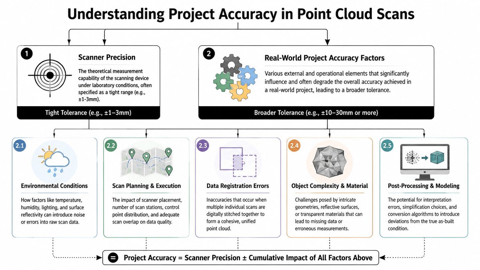
The Gap Between Scanner Precision and Project Accuracy
Scanner spec sheets create a lot of confusion. They tell you the device’s measurement capability under controlled conditions. They don’t tell you what your full building-scale deliverable can support after registration, overlap, site constraints, and modeling.
That’s the difference between laser scanning accuracy and project accuracy. Teams ignore that gap at their own risk.
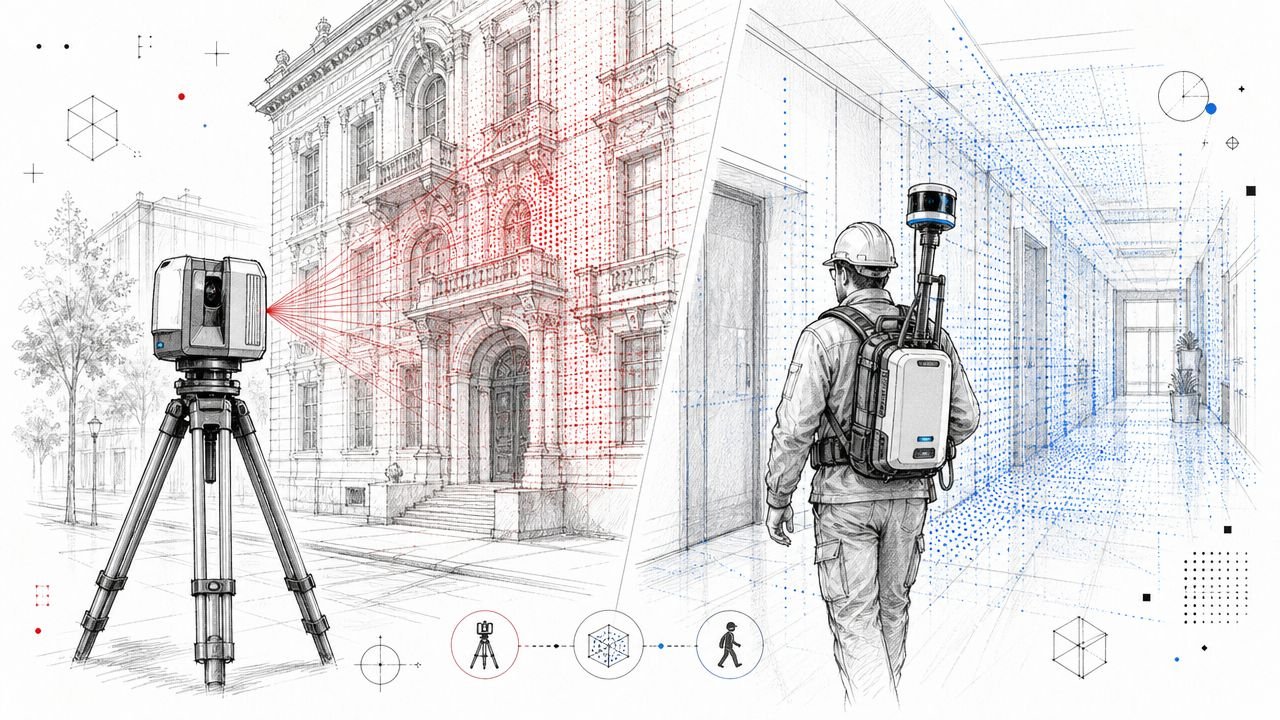
Static versus mobile capture
Tripod-mounted terrestrial laser scanners are still the safer choice when the project needs survey-grade fidelity. Mobile systems can be the right operational answer in occupied spaces or fast documentation work, but the trade-off is real. Scene3D notes that mobile laser scanners often produce 4 to 6mm accuracy, while static systems retain higher survey-grade precision.
That doesn’t make mobile capture “bad.” It makes it purpose-dependent.
If your downstream use is broad space planning, mobile may be fine. If your downstream use is fabrication-sensitive geometry, you need to be more selective about capture method, verification steps, and modeling assumptions. That’s the same judgment behind a disciplined scan to BIM production workflow. The tool choice should follow the tolerance the project needs.
Where project accuracy degrades
The biggest sources of error are usually operational, not theoretical:
Registration drift
Multiple scans have to be aligned into one coordinate system. Every alignment decision affects the combined cloud.Poor scan planning
Weak target distribution, difficult access, or uneven station placement can reduce confidence in areas between setups.Range and angle issues
Surfaces farther from the scanner, or hit at shallow angles, tend to produce noisier usable data.Site conditions
Dust, humidity, reflective surfaces, and active construction all make clean capture harder.Material behavior
Surface color, gloss, and material type affect ranging quality. Research published in PMC reports that white painted surfaces showed the lowest ranging error, concrete surfaces showed the highest ranging error, and dark-colored targets produced higher point cloud noise than light-colored targets.
What to ask for before modeling starts
Don’t accept “the scanner is accurate” as a project answer. Ask for evidence tied to the actual deliverable.
| Question | Why it matters |
|---|---|
| Was the capture static, mobile, or mixed? | Method affects usable accuracy and speed |
| Is there a registration report? | It shows achieved alignment quality, not just vendor claims |
| Where were the difficult materials and reflective surfaces? | Those areas may need filtering or targeted verification |
| Which areas were high-risk for precision-dependent design? | They may need supplemental field checks |
Practical rule: The scanner spec is not your modeling tolerance.
The Occlusion Problem What Your Scan Did Not See
A renovation team lays out new work from a clean point cloud, then opens the ceiling and finds a steel brace, abandoned conduit, and a low hanger line that never appeared in the scan. The scanner did its job. The project still got bad input.
Occlusion causes that gap. A scanner only records surfaces it can see from a given position. Blocked areas do not come through as uncertain or incomplete. They often come through as empty, and that is what makes them dangerous.
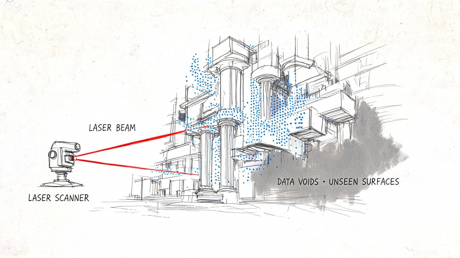
Common places where occlusion breaks trust
Occlusion shows up in ordinary project conditions, not unusual ones. Occupied rooms hide wall bases, column faces, and floor edges behind furniture and storage. Mechanical and electrical rooms hide supports, access clearances, and penetration paths behind equipment and pipe racks. Renovation areas often have debris, protection, staged material, or temporary partitions that block the exact surfaces the design team needs to verify.
Above-ceiling work is a frequent failure point. The cloud may show the underside of ductwork or the bottoms of hangers while missing the structure above, the top side of services, or the actual routing space available for new work.
The same problem happens below equipment, behind casework, inside shafts, and in tight interstitial zones. Those are usually the places where field crews need the most confidence.
Why extra scan positions help, and where they stop helping
Multiple setups reduce blind spots. Good overlap improves registration and fills coverage gaps where another station has a clear line of sight. It does not create data for a surface that no station ever saw.
That distinction matters in practice.
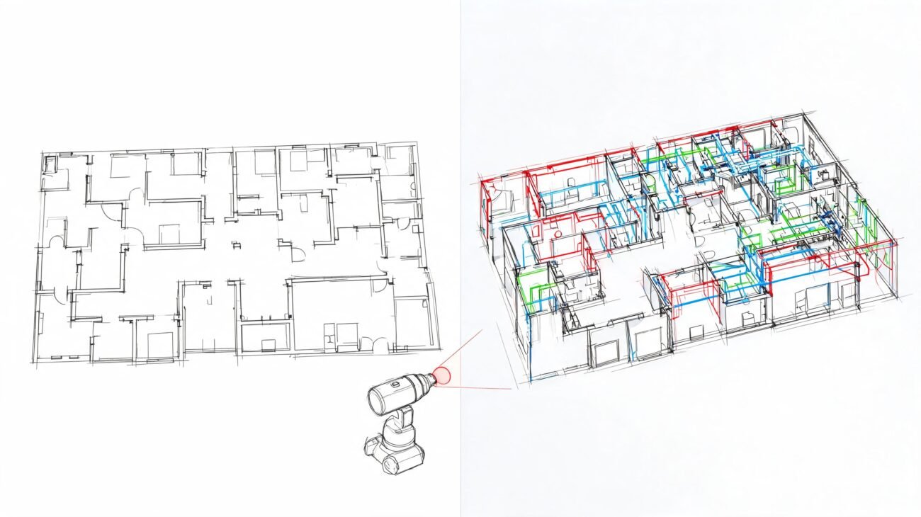
A dense room can still produce a polished-looking cloud with critical holes in it. A modeler may have enough visible geometry to place walls, equipment, and major services, but not enough evidence to define offsets, support locations, or tie-in clearances accurately. The result is a model that looks complete at coordination scale and fails at installation scale.
Typical high-risk blind spots include:
- Occupied tenant areas where furniture and stored items block perimeter conditions
- Congested MEP rooms where equipment hides structure, valves, supports, and penetrations
- Above-ceiling spaces where visible lower surfaces hide the actual anchor or routing constraints
- Below raised equipment or platforms where voids mask slab conditions and service conflicts
- Tight shafts and interstitial spaces where scanner position options are limited
A blank area in the cloud can mean hidden geometry, not open space.
That is where teams over-read the scan. The failure usually starts with a reasonable assumption made under schedule pressure. Someone infers a straight wall behind storage, a clear zone above a ceiling, or a continuous slab edge behind debris. Then that assumption gets modeled, coordinated, priced, and installed as if the cloud proved it.
The fix is procedural, not theoretical. Mark occluded zones before modeling starts. Require modelers to distinguish scanned geometry from inferred geometry. Send high-risk areas back for targeted field verification, selective opening, or supplemental capture. If the team cannot state what was visible at the time of scanning, they should not treat that area as reliable as-built input.
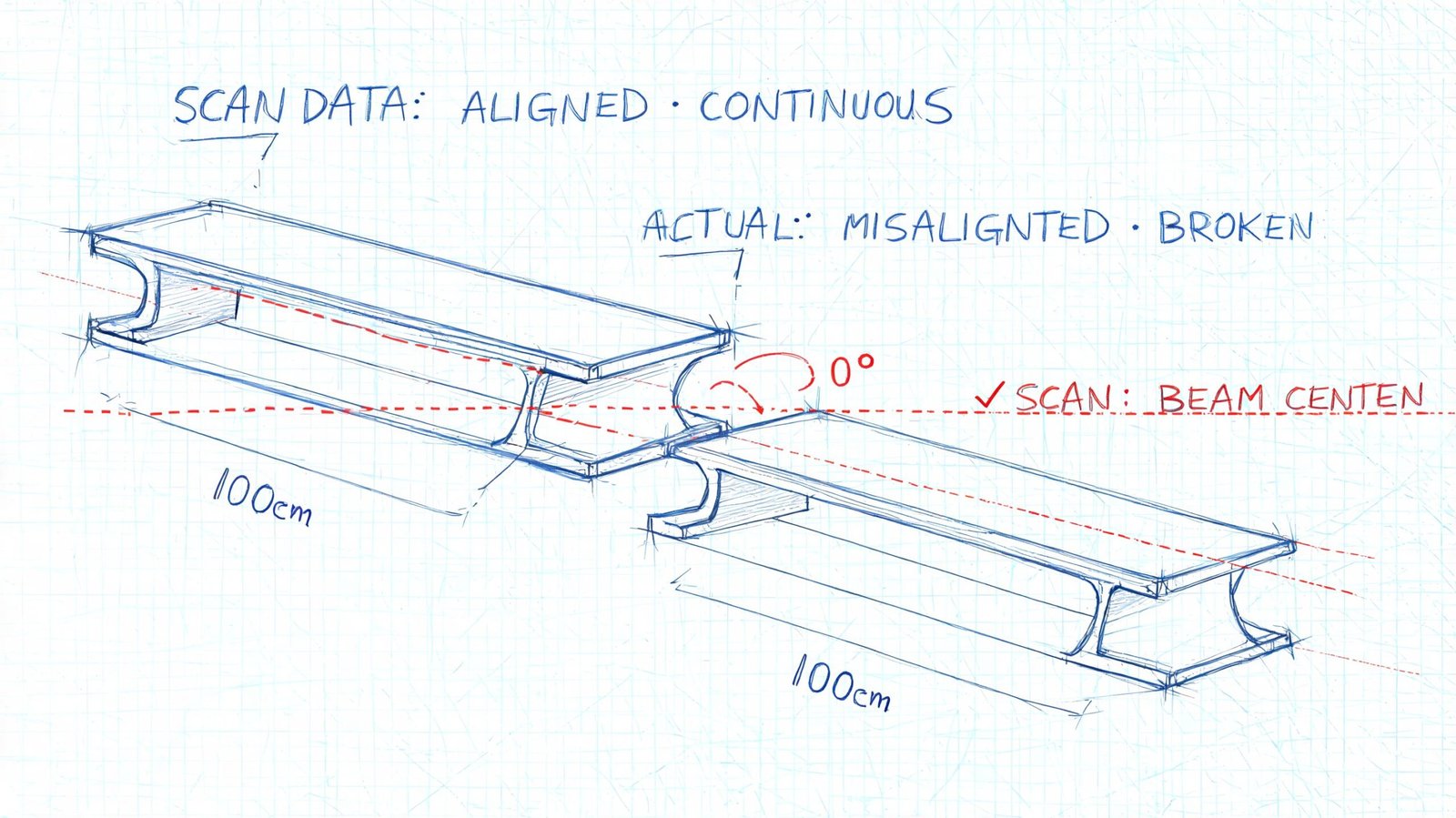
When Point Cloud Data Becomes Outdated
A point cloud is a timestamp, not a living record.
That sounds obvious, but teams still treat scan data as durable truth long after the conditions have changed. The longer the design timeline, the more dangerous that assumption becomes.
Typical failure patterns
One common pattern is using an early scan through the full design cycle without checking whether the building changed. Tenant improvements, maintenance work, equipment replacement, demolition sequencing, and partial rough-in can all make the original cloud stale.
Another is phased renovation work. The scan may show demolished elements that no longer exist, while missing the rough-in or structural exposure created later. That creates a model that is technically traceable to the scan but operationally disconnected from the field.
Conditions that move over time
Not every geometry problem is caused by poor scanning. Some building conditions aren’t stable.
- Load-dependent deflection can change how slabs or structural elements present at different times.
- Seasonal movement affects timber and masonry in ways teams sometimes underestimate.
- Temperature and moisture shift dimensions enough to matter in precision-sensitive work.
That doesn’t mean point cloud scan data is unreliable. It means the data is reliable for the moment it captured.
Treat the scan date like a design input, not a file property.
Every project record should note the scan date, occupancy status, and relevant site condition at time of capture. If the design runs long or the site changes materially, critical areas should be rechecked before issuing for construction. That one discipline prevents a lot of false certainty from moving downstream.
Interpretation Errors During As-Built Modeling
Even if the cloud were clean, current, and fully visible, the BIM model still wouldn’t be neutral. A model is an interpretation layer placed on top of raw capture.
That’s where a second category of as-built modeling accuracy problems enters the workflow. The error isn’t in the point cloud itself. It’s in the choices made while converting points into walls, floors, ducts, pipe runs, steel members, and reference planes.
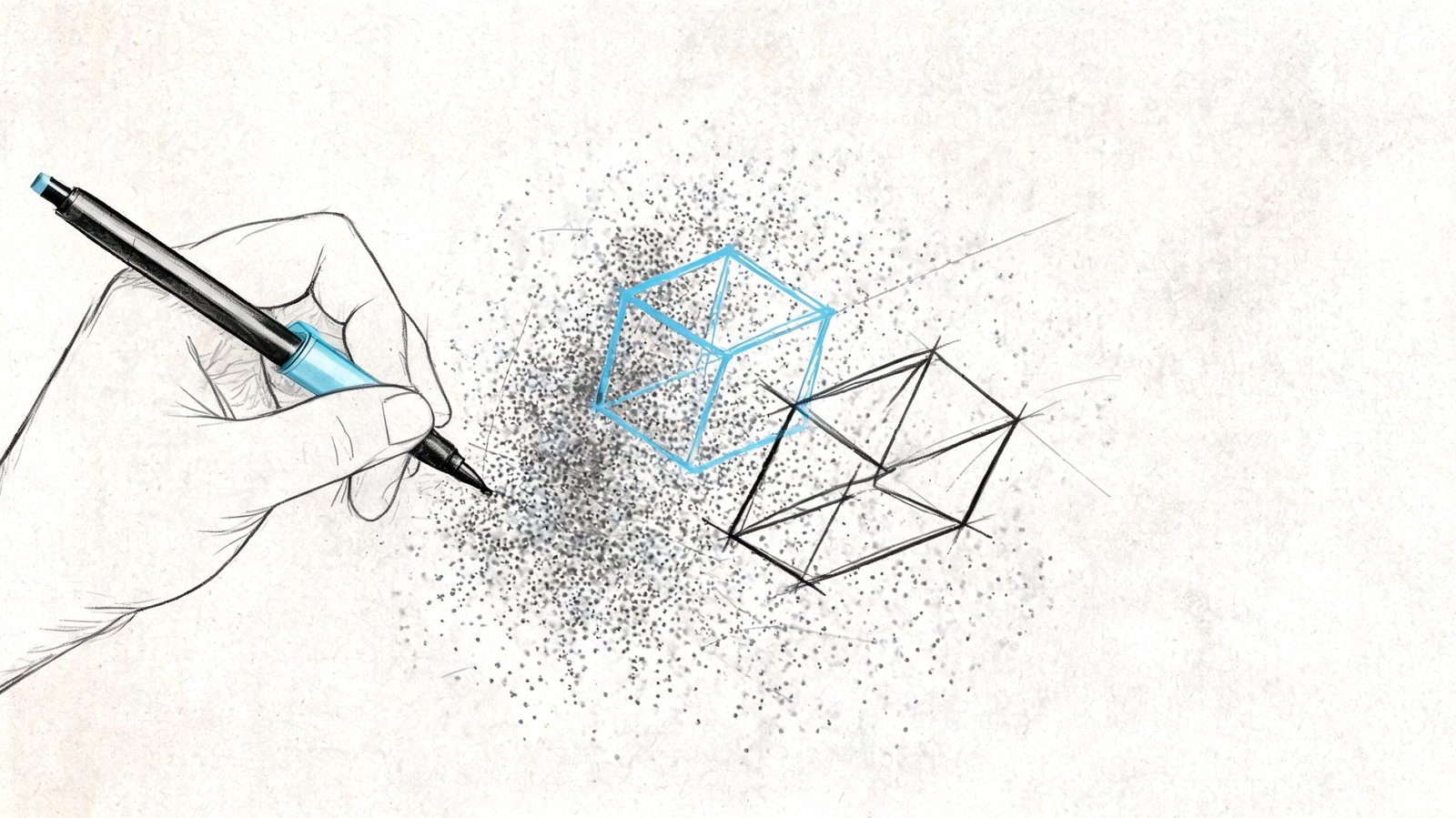
What modelers do that changes the truth
A rough masonry wall might be modeled as a clean flat face. A warped slab may become a level plane. A partially visible beam behind finishes might be inferred from adjacent geometry and placed as though it were verified. A noisy ceiling cloud may be interpreted as the wrong surface altogether.
Those decisions are sometimes necessary. They’re also risky if the model doesn’t clearly distinguish verified geometry from inferred geometry.
The most common interpretation mistakes
Averaging irregular surfaces
Good for cleaner authoring. Bad for tight tolerance work.Inferring hidden conditions
Sometimes unavoidable. Never harmless when it’s undocumented.Misidentifying systems
In noisy data, a pipe, conduit, or support can be modeled as the wrong element type.Cleaning up dimensions
Snapping to round numbers makes models easier to read and easier to trust for the wrong reasons.
In Revit-based production, this is especially important. A clean point cloud Revit model can look far more certain than the source data justifies. Teams that build disciplined QA into point cloud cleanup and modeling review catch this earlier because they treat interpretation as a controlled process, not a drafting shortcut.
A delivered as-built model is not the scan. It’s a professional interpretation of the scan.
Project managers should review it that way. Ask what was observed, what was inferred, and where the model was simplified for production reasons.
Real Project Risks from Over-Trusting Scan Data
The consequences of over-trusting point cloud accuracy are rarely abstract. They usually show up when a downstream activity demands more certainty than the scan-to-model chain can realistically support.
Fabrication and envelope work
Facade and curtain wall work often exposes this first. The team dimensions directly from the cloud, assumes the geometry is fully dependable, and pushes that certainty into fabrication decisions. If the cloud carried registration issues, surface noise, or interpretation simplifications, the panel geometry may not reflect the field condition that installers face.
That doesn’t mean scans shouldn’t inform fabrication. It means fabrication-critical dimensions need verification beyond the cloud when tolerances are tight.
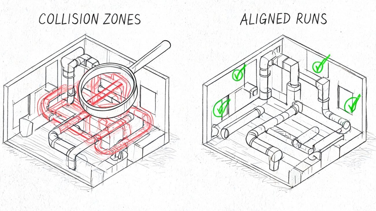
Renovation coordination and field conflict
In MEP retrofit work, teams often coordinate new systems against an as-built model generated from partial visibility in crowded rooms or above ceilings. The coordination meeting goes well because the model appears complete. Then demolition exposes a support, offset, or routing condition that was modeled from assumption rather than observed geometry.
That’s where RFIs multiply. Not because scan to BIM failed, but because the team trusted inferred conditions like measured conditions.
Compliance and structural decisions
ADA-related dimensions, floor transitions, clearances, and slope-sensitive conditions can also become risky if the scan basis isn’t validated at the points that matter. The same goes for shoring, underpinning, and existing structural geometry in difficult-access zones. Once the project relies on those dimensions for approval, sequencing, or temporary works, uncertainty becomes expensive.
Here’s the recurring pattern:
| Decision type | What goes wrong |
|---|---|
| Fabrication | Team assumes modeled geometry is field-ready |
| Coordination | Assumptions in occluded zones are treated as verified |
| Compliance review | Precision-sensitive dimensions aren’t field-checked |
| Structural planning | Concealed or hard-to-reach conditions are over-modeled |
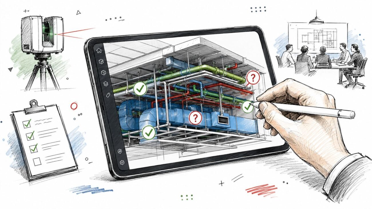
This is why teams should think in terms of fit-for-purpose accuracy, not generic scan confidence. A reality capture workflow can be excellent and still require targeted verification before major commitments. That’s the practical value of a disciplined reality capture process in production BIM work. It protects predictability by showing where the data is strong and where the workflow needs a checkpoint.
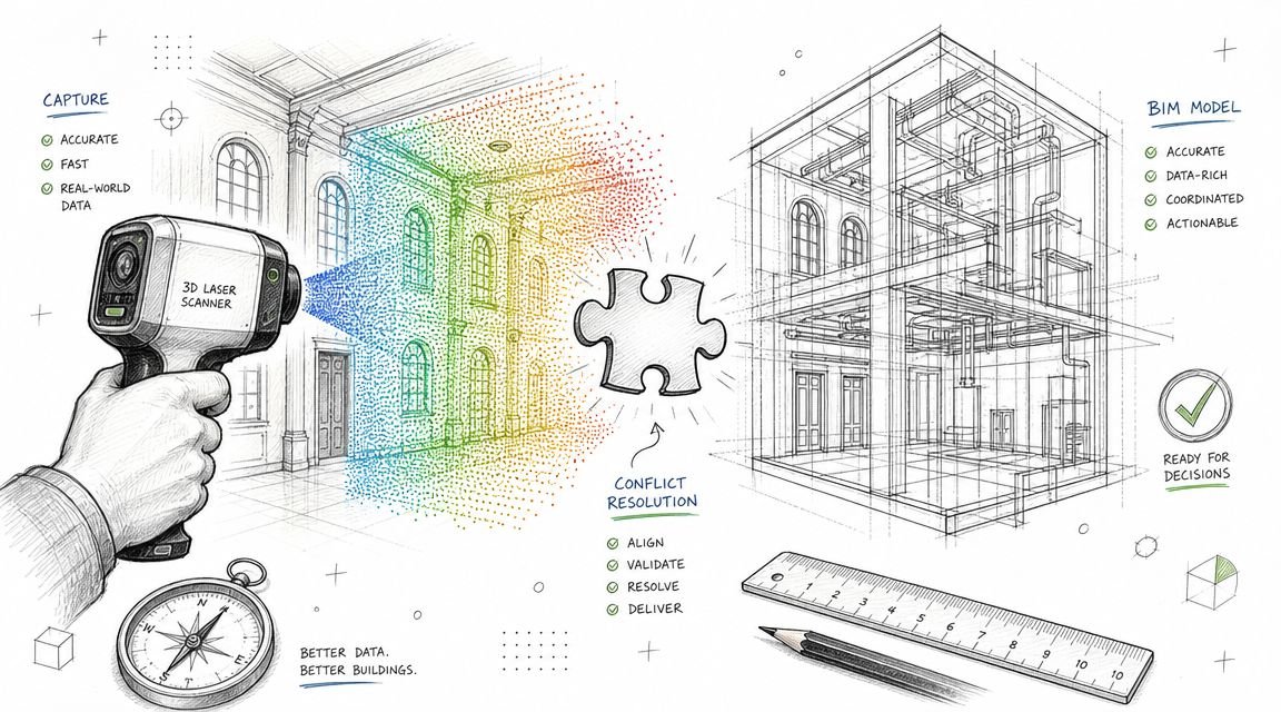
A Practical Framework for Using Point Clouds Reliably
The right response isn’t skepticism. It’s control.
Point cloud scan data is one of the best inputs available for existing conditions work. But it only becomes dependable inside a workflow that separates captured fact from likely interpretation and current condition from stale record.
A working QA framework
Use this on every scan to BIM workflow:
Review the registration output before modeling begins
If nobody can show how the scans were aligned and assessed, the team is already guessing about project accuracy.Map occlusion areas early
Mark blocked zones, low-visibility rooms, above-ceiling unknowns, and cluttered floor areas in the project record.Set accuracy by use case
Space planning, permit documentation, coordination, and fabrication do not need the same confidence level.Verify the dimensions that carry project risk
Don’t field-check everything. Field-check the dimensions that drive cost, fit, approval, or sequencing.Track scan age and trigger revalidation when needed
If the building changed, your assumptions should change with it.
Avoid the density trap
One industry question still gets too little practical attention: how much density does the project need? OptimaAero’s discussion of point cloud density highlights the real trade-off: over-scanning increases cost, while under-scanning creates modeling gaps. That’s not just a scanning decision. It’s a production decision.
A mature workflow doesn’t chase maximum data. It defines the data needed to support the next reliable decision.
Point cloud data has transformed existing conditions work. It’s faster, richer, and more useful than traditional field measurement for most building documentation tasks. But it is not infallible truth. It is high-density raw evidence with known limits.
If your team understands those limits, point cloud scan to BIM becomes a strong foundation. If your team ignores them, the same data can carry false certainty deep into design and construction.
If you're working from scan data and want a more dependable path from capture to model, BIM Heroes helps AEC teams build that structure into production. We regularly support scan to BIM, as-built modeling, and coordination workflows where the core value isn't just creating a model. It's identifying what the point cloud can support, what needs verification, and where a disciplined QA process protects schedule, margin, and downstream decisions.