


A commercial electrical design can pass plan review and still fail the contractor on site. The panel schedule may look complete, yet the late EV charging scope has nowhere practical to connect. Conduit may be sized correctly, but its route collides with ductwork, access panels, or structural framing. During commissioning, a long feeder run can expose voltage-drop problems that weren't visible in the plan set.
Those failures aren't usually caused by one bad component. They come from treating electrical system design as a standalone engineering task instead of a coordinated BIM workflow. Code compliance matters, but so do clear documentation, constructible routing, dependable schedules, and decisions that other disciplines can build around.
For project managers, BIM managers, principals, and firm owners, the difference is commercial. Every unresolved conflict can become an RFI, redesign cycle, field change, or schedule disruption. A buildable electrical model protects margin by making decisions visible before installation begins.
When Electrical Designs Fail in the Field
The project looked controlled at the permit milestone. The electrical sheets had been reviewed, the equipment was selected, and the contractor mobilized with an approved set. Then the coordination meeting exposed the first problem: the main cable tray route occupied the same ceiling zone as a mechanical trunk duct.
The second problem appeared in the panel schedule. An EV charging package had been added after the design development milestone, but the schedule still reflected the earlier load assumptions. The contractor could identify a panel location, but not a clean path, spare capacity strategy, or coordinated connection detail.
The third issue surfaced during commissioning. A long feeder remained within the project's stated code approach, but the combined downstream resistance produced poor lighting performance. The contractor reported flicker, and the design team had to revisit conductor sizing and distribution placement after installation work had already advanced.
Field lesson: A code-compliant drawing isn't automatically a buildable electrical system.
The margin disappears in the gap between those two conditions. Engineers may have completed the calculations, but the BIM team still needs to translate the intent into equipment clearances, modeled routes, accurate circuit data, coordinated penetrations, and sheets that match the model. If those tasks happen late, the team discovers conflicts when changes are most expensive.
The coordination risk is cumulative
Electrical systems compete for some of the most constrained areas in a commercial building. Ceiling plenums, risers, electrical rooms, shafts, and service corridors also carry mechanical, plumbing, fire protection, structural, and architectural requirements. A small routing assumption can affect access, maintenance, firestopping, installation sequence, and future tenant work.
The practical response is to establish decision checkpoints early. Lock equipment locations before detailed routing, confirm service and metering assumptions, review life-safety loads with the architectural and code teams, and federate models before the design looks “finished.” A production team that waits for perfect information often creates more rework than a team that documents assumptions and flags them for resolution.
Core Components of Electrical System Design
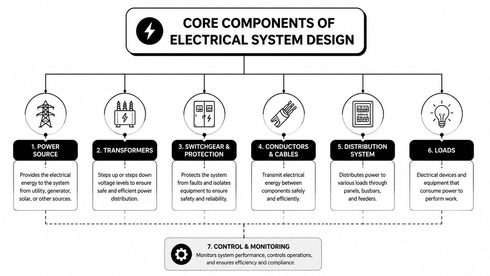
A useful electrical model starts with a complete system map, not a collection of symbols. Commercial electrical system design typically connects the utility service to distribution equipment, branch circuits, lighting, controls, life-safety systems, communications infrastructure, and grounding. Each layer has a different coordination burden and a different documentation requirement.
Start with the source and distribution path
Service entrance and utility coordination establish where power enters the building, how service equipment is arranged, and which utility constraints affect the design. In Revit, that intent becomes service equipment, transformers, switchgear, feeders, equipment clearances, room layouts, and connection information. The model must leave realistic working space, not just represent equipment by its footprint.
Distribution and panel schedules carry the system's logic. Panels, breakers, feeders, circuit numbers, loads, and phase information should remain consistent across the model, schedules, one-line diagrams, and construction sheets. A schedule that doesn't match the modeled circuits is a production defect, even if the graphic presentation looks polished.
Branch circuiting and receptacle layouts connect the distribution system to rooms, equipment, and user requirements. The BIM deliverable includes receptacles, disconnects, junction boxes, homeruns where required, circuit assignments, and coordinated device locations. Architectural millwork, casework, equipment layouts, and accessibility requirements can all change the final placement.
Treat controls and low-voltage scope as coordination work
Lighting design includes fixtures, switching, control zones, emergency lighting, and links to reflected ceiling plans. Controls must coordinate with room geometry, ceiling types, daylight strategies, occupancy requirements, and the control contractor's scope. A fixture family with no usable mounting or access information creates a visually complete but operationally weak model.
Fire alarm, telecommunications, security, audiovisual, access control, and data infrastructure may sit in separate design packages, but their pathways still compete for space. Model the scope boundaries clearly, identify who owns devices and pathways, and document unresolved interfaces before they become field questions.
Grounding and bonding deserve the same discipline. The model may not represent every conductor at every stage, but it should communicate equipment connections, grounding points, bonding requirements, and coordination interfaces with structural and utility systems.
Production rule: Model the information needed for decisions, installation, review, and handoff. More geometry isn't the same as more value.
A BIM manager should scope deliverables by system, LOD, view, schedule, and coordination milestone. That makes it easier to separate engineering decisions from production tasks, assign the right reviewer, and prevent a late request for “complete electrical modeling” from becoming an unpriced rework cycle.
Load Calculations and Sizing Rules That Matter
Electrical sizing starts with the load study, not with a preferred panel size or a familiar conductor schedule. NEC Article 220 provides the framework for calculating branch circuits, feeders, and services, and it uses demand factors rather than automatically treating every connected load as operating at full capacity. The cited NEC Article 220 load calculation guide also identifies the rule that continuous loads expected to operate for three hours or more are calculated at 125% of their rating, with the largest motor also taken at 125%.
That information affects more than the electrical engineer's spreadsheet. It controls panel schedules, feeder tags, transformer selection, switchboard space, equipment room planning, and the capacity assumptions that the BIM team carries through the model.
Demand and diversity change the physical design
A demand factor is maximum demand divided by connected load, and it is always less than 1. A diversity factor is the sum of individual maximum demands divided by the coincident system maximum, and it is greater than 1. These are not interchangeable terms, and using a generic assumption can produce either oversized equipment or inadequate capacity. The EC&M explanation of diversity and demand factors is a useful reference for keeping the distinction clear.
| Factor Type | Definition | Value Range | Design Impact |
|---|---|---|---|
| Demand factor | Maximum demand divided by connected load | Always less than 1 | Can reduce calculated feeder, transformer, and service requirements when supported by actual occupancy and operating assumptions |
| Diversity factor | Sum of individual maximum demands divided by coincident system maximum | Greater than 1 | Helps evaluate how independently occurring peaks affect shared system sizing |
| Continuous-load rule | Loads expected to run for three hours or more are calculated at 125% of rating | 125% for the stated NEC calculation rule | Increases the calculated load used for affected circuit and equipment sizing |
A diversified load study can reduce transformer and switchboard sizing substantially without reducing reliability, but only when the factors reflect occupancy type, duty cycle, and operating profiles. Underestimating coincident peaks has the opposite effect. It can produce nuisance trips, stressed conductors, and operational complaints that the construction model never predicted.
Voltage drop is a performance decision
Common design targets are 3% for branch circuits, 3% for feeders, and 5% combined feeder plus branch circuits, based on NEC informational guidance summarized in this voltage-drop calculation reference. These targets should be reviewed as a system, not as isolated circuit checks.
A feeder can remain code-acceptable while the downstream branch circuit pushes the total drop beyond the recommended combined target. Delivered voltage affects motor starting torque, lighting output, and electronic equipment stability. Designers typically respond by shortening runs, upsizing conductors, or moving distribution closer to the load center instead of relying only on minimum ampacity sizing.
For BIM teams, the review questions are practical:
- Trace the run: Does the model show the actual route length and distribution path?
- Check the load: Does the panel schedule reflect the latest equipment and continuous-load assumptions?
- Review the mitigation: Is the selected response visible in equipment placement, conductor data, or feeder routing?
- Protect the decision: Does the model and sheet set explain the design intent well enough for construction review?
The electrical load calculation workflow is most useful when it connects calculations to model parameters, schedules, and coordination checkpoints rather than treating the study as a file that sits outside production.
Code Compliance Across IBC, IECC, and NEC
Code compliance works best when the team builds it into model development instead of waiting for a final markup cycle. The IBC and energy codes define the compliance path, while the NEC governs many of the electrical calculation and installation decisions that appear in the drawings, schedules, and equipment documentation.
IBC Chapter 13 serves as the energy-efficiency bridge chapter. IBC §1301.1 directs buildings to comply with the IECC, while IBC §1301.1.2 allows commercial buildings to use ASHRAE 90.1-2019 as an alternative compliance path, as summarized in this IBC energy-efficiency code reference.
Turn the selected path into model requirements
The code path should be identified during project setup. It affects the information the electrical model must carry, the schedules that need review, and the coordination responsibilities assigned to the BIM team.
For commercial projects, compliance documentation may include:
- Whole-building measurement: Provide the modeled equipment, meter locations, and documentation needed for electrical energy measurement.
- End-use submetering: Identify major end uses and coordinate metering points with distribution equipment.
- HVAC consumption measurement: Coordinate the electrical data associated with HVAC systems and their metering requirements.
- Lighting monitoring: Carry lighting energy monitoring information into schedules, controls documentation, and construction details.
- Accessible reporting: Confirm that the project documentation supports the required reporting and operational handoff.
A 2021 IECC commercial compliance summary describes expanded requirements for whole-building electrical energy measurement, major end-use submetering, HVAC electrical consumption measurement, lighting energy monitoring, and accessible reporting. Those requirements can drive scope in construction documents and BIM coordination deliverables, especially when the electrical team, controls contractor, equipment vendor, and owner have different information expectations.
Review code data before sheets are issued
The most reliable workflow uses a compliance checklist at each design milestone. Confirm service and distribution assumptions, emergency and life-safety loads, metering ownership, panel naming, circuit conventions, equipment parameters, and required notes before the permit set. The model should make those decisions traceable.
This approach also helps separate code questions from modeling questions. Engineers retain responsibility for design interpretation, while production teams verify that approved decisions appear consistently in views, schedules, families, annotations, and coordinated model elements.
MEP Coordination and Clash Detection Workflows
Electrical systems often get whatever space remains after mechanical and plumbing routing. That sequence is understandable on a crowded project, but it produces weak coordination. A buildable workflow reserves coordination attention for electrical distribution, cable tray, conduit, equipment access, and installation sequence before the ceiling and shaft zones become unavailable.
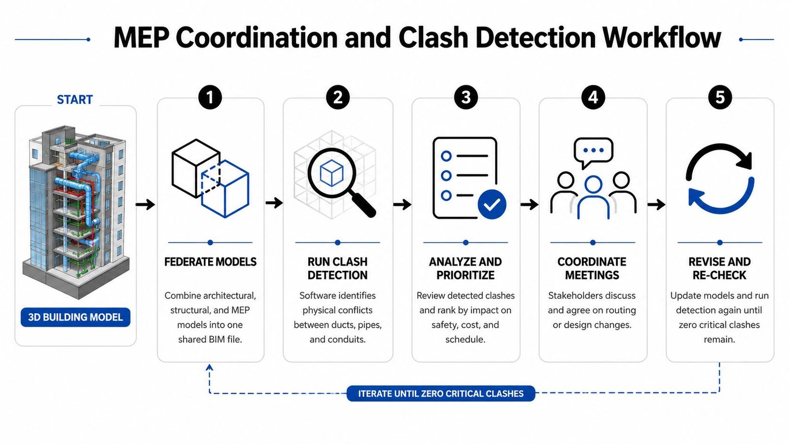
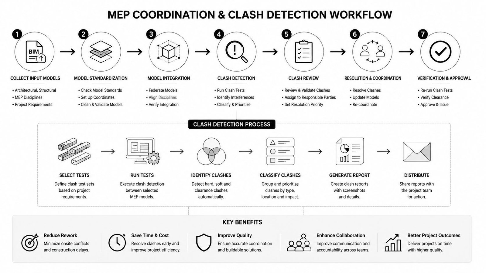
MEP BIM clash detection identifies physical clashes, clearance issues, and sequencing conflicts between mechanical, electrical, and plumbing systems before construction begins. In practice, that means reviewing more than hard intersections. A route can avoid a geometric clash and still block a panel door, obstruct a valve, violate a maintenance zone, or make installation impossible.
Use a controlled coordination sequence
A workable sequence begins with a reliable architectural and structural background. Mechanical teams establish major duct routes, plumbing and fire protection teams coordinate their primary services, and the electrical team then routes conduit, cable tray, feeders, and equipment connections against current constraints. The sequence shouldn't turn electrical into an afterthought. The BIM execution plan needs a defined review point where electrical routing receives the same priority as every other MEP system.
A practical cycle looks like this:
- Federate current models: Confirm coordinates, levels, linked files, worksets, and model versions before running tests.
- Set meaningful rules: Separate hard clashes from clearance and access checks. Exclude known overlaps that don't represent field risk.
- Prioritize by consequence: Address life-safety equipment, service routes, major feeders, shafts, and equipment access before minor secondary conflicts.
- Review in context: Use section cuts, enlarged plans, elevations, and 3D views to understand the installation condition.
- Assign ownership: Record the responsible discipline, decision, due date, and required model revision.
- Re-run after changes: Close the loop with a new federated model and a verified clash report.
- Publish controlled outputs: Issue coordinated views, marked-up reports, and model revisions through the agreed platform.
The BIM Heroes clash detection service can fit into this workflow when a project team needs additional production capacity for federating models, reviewing conflicts, and documenting resolution status.
Prioritize constructability over a clean report
A report with fewer clashes isn't automatically a better result. Teams can suppress conflicts too aggressively, classify access problems as non-issues, or close a clash without checking the revised route. The useful measure is whether the coordinated model gives the contractor a clear installation path and preserves required access.
Coordination checkpoint: Don't close an electrical clash until the revised route works in plan, section, elevation, and the installation sequence.
BIM managers should also track repeated conflict types. If cable trays repeatedly collide with duct mains, the project may need a routing convention or reserved corridor. If equipment clearances keep failing, the team should correct families, room layouts, or design assumptions instead of resolving each symptom independently.
Designing for Electrification and Future Loads
Meeting today's minimum load requirement isn't the same as designing a building that can operate through future tenant changes. EV charging, battery storage, smart controls, and renewable integration have moved from unusual additions to practical design considerations for many commercial and institutional projects.
The difficult question isn't just how to add load. It's how to document uncertainty without overbuilding the initial system. A project may need reserved panel space, future conduit pathways, electrical room capacity, utility coordination, and a clear strategy for diversified demand. Those decisions belong in early design, when routing and equipment locations can still change without disrupting construction documents.

Reserve capacity deliberately
A vague note saying “future EV chargers” doesn't protect the owner. The model should identify where future equipment could connect, which panels or distribution sections are intended to serve it, how pathways are reserved, and which assumptions require utility confirmation. Panel schedules should distinguish active loads from future provisions so later fit-outs don't force a complete redesign.
Battery storage and renewable systems add their own coordination questions. The design team needs to consider equipment location, access, disconnects, interconnection requirements, fire and life-safety interfaces, and monitoring. BIM production should expose those relationships through coordinated equipment, schedules, clearances, and room layouts.
Keep the initial design proportionate
Overbuilding every component creates unnecessary capital cost and consumes valuable space. Underbuilding creates service upgrades, shutdowns, and disruptive retrofit work. A diversified load study, documented operating assumptions, and a capacity decision log give owners a more defensible basis for choosing what to install now and what to reserve for later.
The BIM model should preserve that decision history. Record future-load assumptions in parameters, notes, panel schedules, and coordination views. That makes tenant fit-outs faster to evaluate and gives the next project team a dependable starting point instead of forcing them to reconstruct the original design logic.
Scaling Electrical BIM Production Without Sacrificing Quality
Electrical BIM production becomes difficult to scale when every project starts from a different template, naming system, family library, and review habit. The result is predictable. Senior staff spend time correcting preventable errors, coordinators chase inconsistent data, and project managers absorb rework that wasn't included in the fee.
Production maturity protects margin. A mature workflow uses template discipline, documented modeling standards, QA checkpoints, decision gates, and standardized deliverables. It doesn't eliminate engineering judgment. It makes approved judgment repeatable across views, schedules, models, and issue responses.
Evaluate capability, not hourly cost
An outsourcing partner should fit into the project's information environment rather than create a parallel one. Confirm how the team handles model intake, design assumptions, naming conventions, family standards, revision control, clash reports, and final QA. Dedicated delivery pods can reduce communication overhead when roles are clear and the same reviewers stay close to the project.
The collaboration stack matters too. Electrical BIM deliverables may need to move through BIM 360, ACC, Procore, or Bluebeam, with outputs in RVT, IFC, DWG, NWD, or BCF formats. A production studio that understands those handoffs can support coordination without forcing the prime consultant or contractor to change its established process.
Quality control should be visible. Ask for sample checklists, review gates, issue logs, model health procedures, and escalation rules. Address communication and IP protection through documented access controls, defined points of contact, and a clear approval process.
BIM project management support is most valuable when it gives the project team predictable checkpoints, not just additional drafting capacity. The same principle applies to outsourced electrical modeling, MEP coordination, shop drawings, construction documentation, as-built modeling, and scan-to-BIM production.
BIM Heroes provides electrical BIM production and coordination support for architecture, engineering, and construction teams, with deliverables that can integrate into established review platforms and documentation workflows. If your team has electrical design files, coordinated models, or scan data waiting for production, BIM Heroes can review the scope, recommend an appropriate LOD, and provide pricing within 24 hours through a free consultation.