Meta description: Radiant hydronic floor heating systems fail in the field when BIM coordination stops at schematic piping. Learn what the model must contain, who owns each decision, and how to prevent RFIs on commercial and multifamily permit sets.
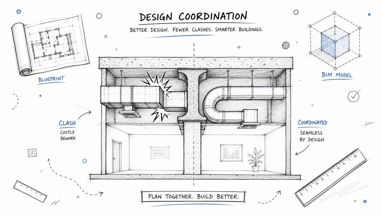
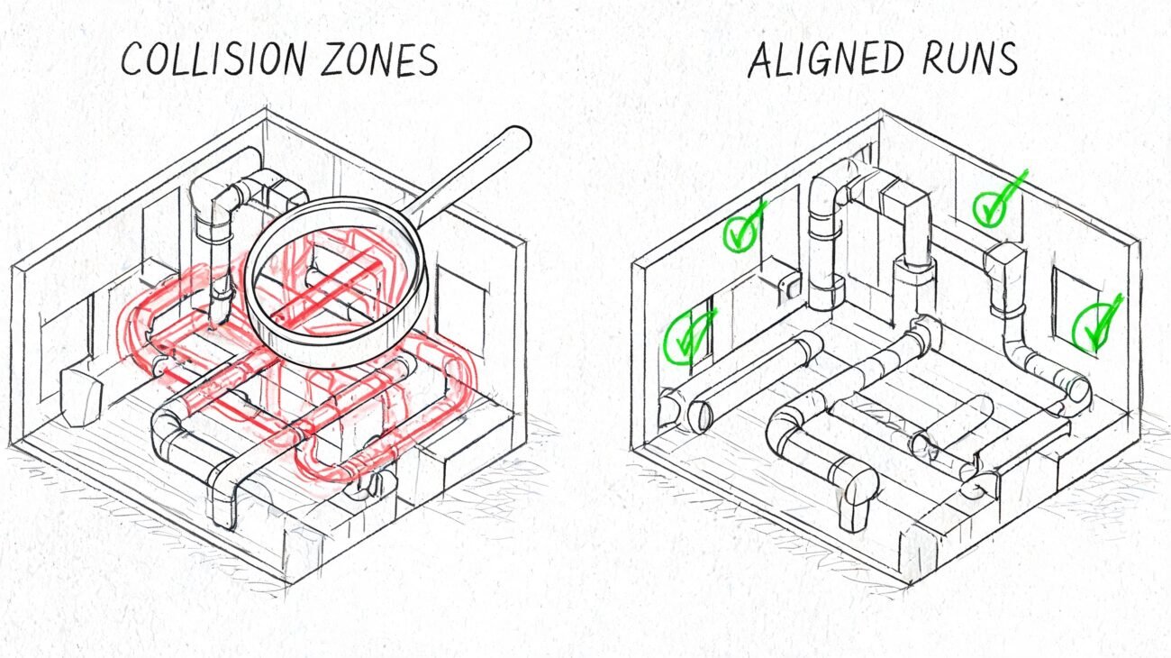
A hydronic radiant floor heating system gets designed cleanly on the mechanical side. Then the architectural team finalizes the floor assembly on a separate track. Nobody checks whether the slab-embedded tubing still has the required cover depth. The issue stays buried until construction, when the installer raises the conflict, the concrete package is already moving, and the RFI lands at the worst possible time.
That's not a hydronic design problem. It's a coordination failure.
On commercial and multifamily work, radiant hydronic floor heating systems put more pressure on the BIM process than many teams expect. The model has to carry real geometry, real clearances, real access needs, and real discipline handoffs. If it doesn't, the permit set may still look complete while the field conditions are already set up to fail.
The Coordination Failure That Sinks Hydronic Projects
The failure usually starts with a false assumption. Mechanical assumes the slab and finish build-up will support the tubing depth. Architecture assumes the floor assembly can be set without mechanical input. Structural moves forward with reinforcing. Then the slab package reaches construction, and everybody discovers the assembly was never coordinated as one system.
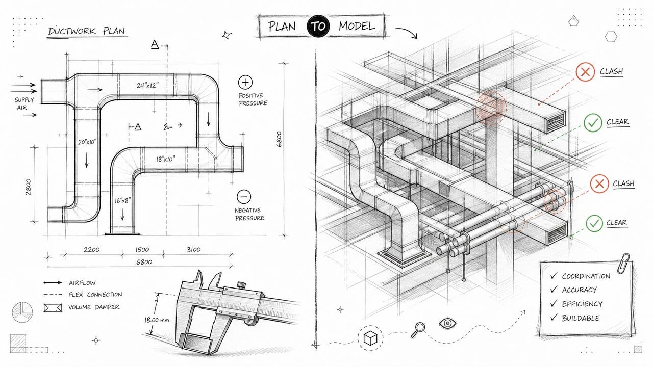
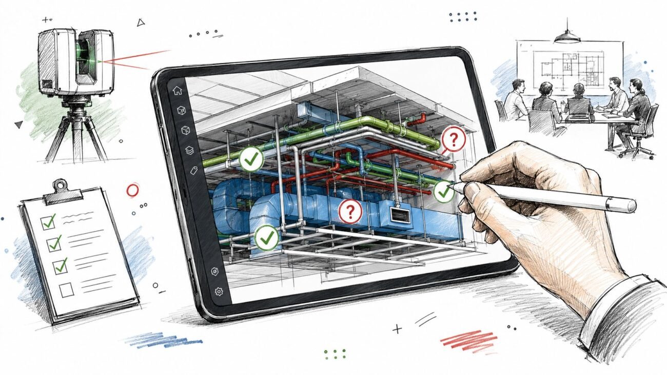
Margins disappear. Once the slab is in play, tubing depth, reinforcing, cover, and finished floor elevation stop being flexible design ideas. They become schedule risk, rework risk, and credibility risk. A good clash detection workflow for MEP projects helps, but hydronic work only gets safer when the model includes the decisions that usually stay buried in markups, emails, and submittal comments.
The firms that handle this well don't wait for Navisworks to expose the problem. They set decision checkpoints early. They force alignment between architectural floor build-up, structural slab design, and mechanical tubing requirements before anybody treats the layout as final.
Field lesson: If the floor assembly and the radiant assembly live in different coordination conversations, the project is already drifting toward an RFI.
Why Hydronic Systems Demand More BIM Coordination
Forced air is usually easier to bound. You coordinate ducts, equipment, clearances, and controls, and most conflicts stay inside familiar MEP zones. Hydronic systems spread coordination across structure, architecture, interiors, and overhead distribution.
The reason is simple. Water doesn't just move through a duct riser and terminate at diffusers. It moves through slab-embedded tubing, radiant panels, fan coil units, manifolds, and low-elevation piping runs. Each condition creates a different clash environment and a different review sequence.
The U.S. Department of Energy identifies hydronic radiant systems as the most popular and cost-effective radiant option in heating-dominated climates, and notes that they typically operate at 85–140°F compared with 130–160°F for traditional baseboard systems, which can improve boiler efficiency and longevity, according to DOE guidance on radiant heating. That operating profile is one reason these systems keep showing up on serious building projects. It's also why teams underestimate the coordination burden. Low-temperature performance is attractive. The geometry still has to work.
Different system types create different coordination problems
A slab-embedded radiant floor heating commercial application is a zone-by-zone coordination problem. The tubing interacts directly with reinforcing steel, post-tension tendons, floor penetrations, and slab thickness. If the slab goes wrong, there's no practical recovery path after the pour.
A radiant ceiling panel layout shifts the fight into the reflected ceiling plan. Now panel dimensions, fixture spacing, ceiling grid logic, and perimeter conditions all matter.
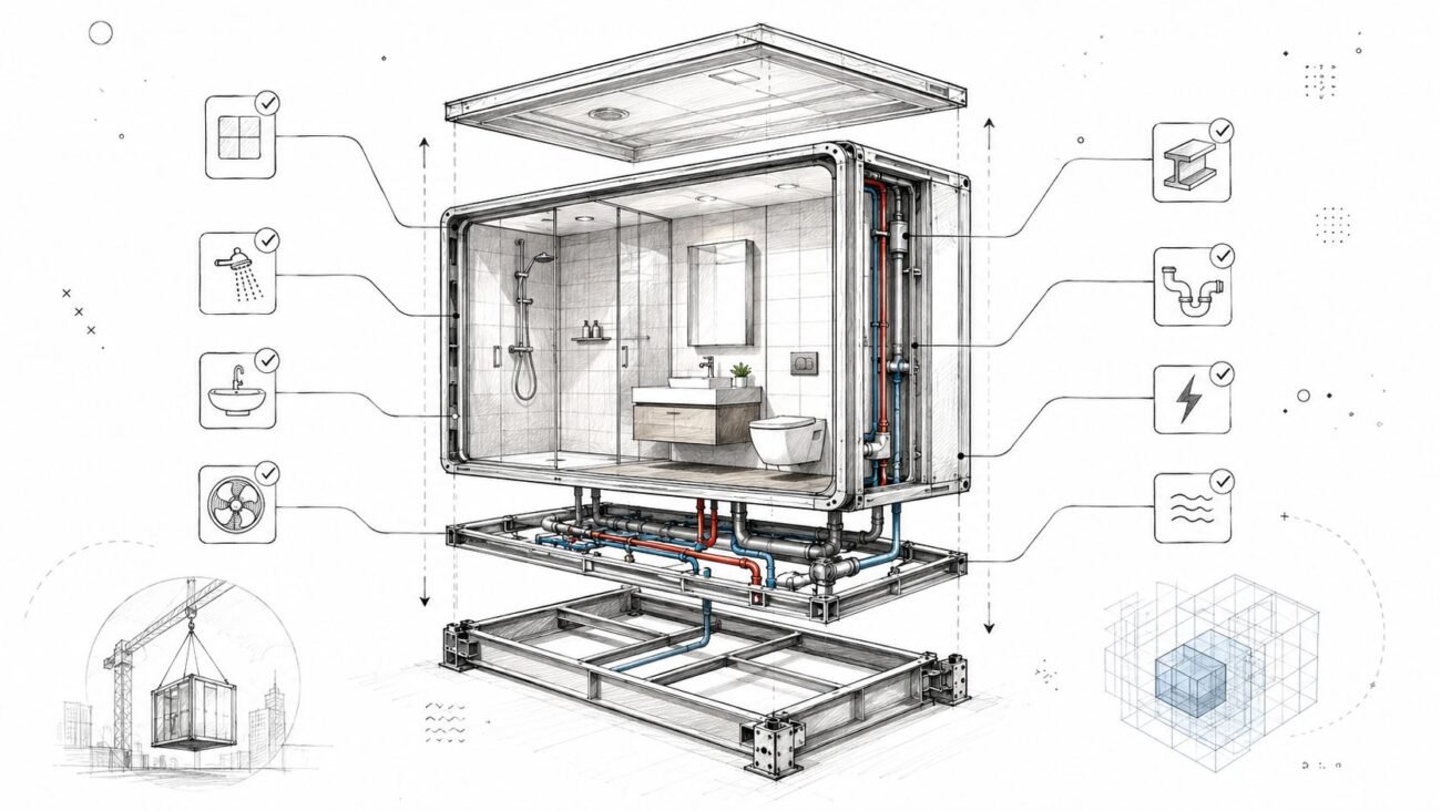
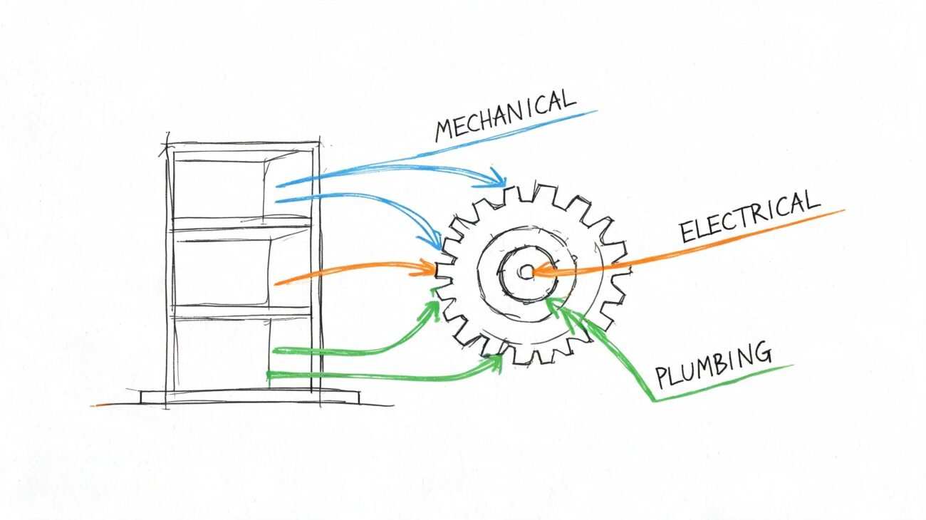
A fan coil-based commercial radiant heating system becomes point-by-point coordination. Every unit brings three discipline touchpoints:
- Mechanical piping: Supply and return connections have to land at workable elevations.
- Plumbing routing: Condensate has to drain with slope or reach a pump.
- Electrical service: Power and controls need actual pathing, not placeholder intent.
Why generic MEP models fail here
Most MEP models are still built to show design intent, not construction consequences. That's enough for many systems. It isn't enough for hydronic heating BIM coordination.
Hydronic projects punish lazy defaults. Generic pipe centerlines, unmodeled insulation, placeholder manifolds, and “typical” access assumptions all pass review right up until they hit framing, slab steel, or ceiling closure.
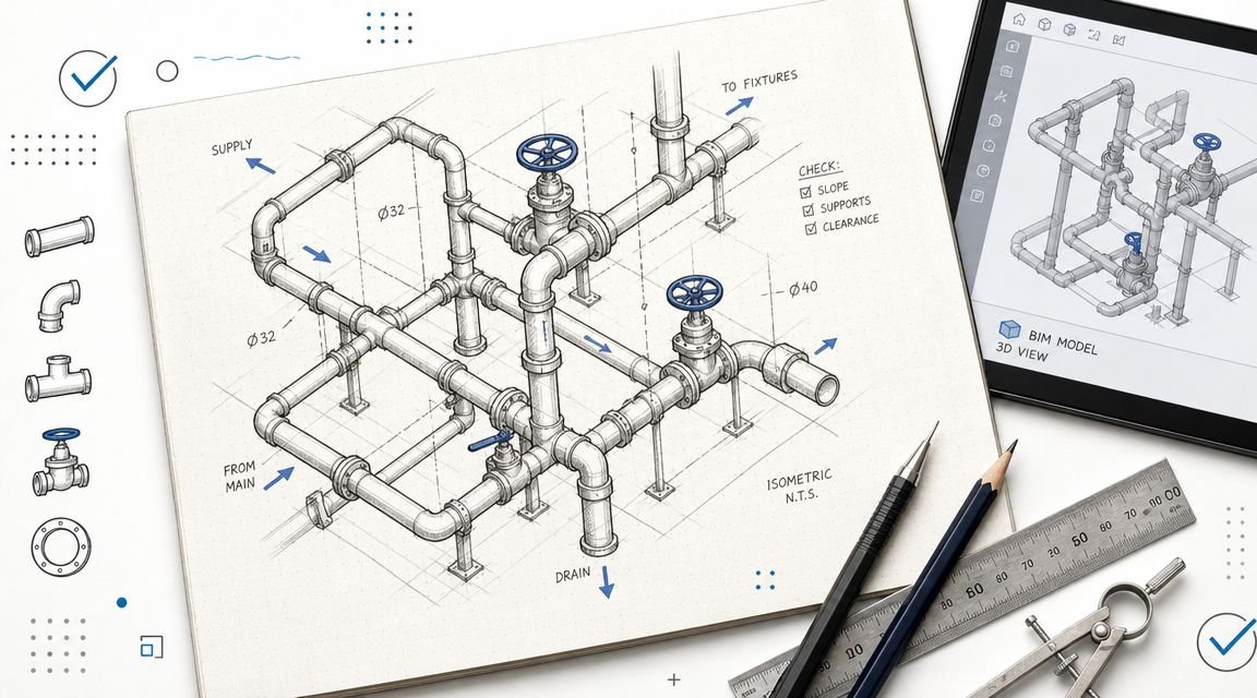
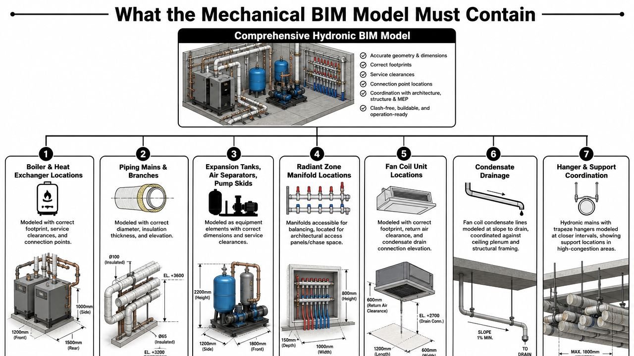
What the Mechanical BIM Model Must Contain
If the mechanical model only shows schematic runs, it won't protect anybody. The model has to be dimensionally honest. That means true sizes, real connection locations, service space, and actual access requirements.
For many organizations, hydronic piping Revit MEP standards either save the job or sabotage it. If your template doesn't force the right content into the model, coordination quality depends on whoever happened to build that file.
Model equipment as installable objects
Boilers, heat exchangers, pump skids, expansion tanks, and air separators need more than a footprint block. Model them with:
- Correct physical dimensions
- Service clearances
- Actual connection point locations
- Maintenance-side access
- Orientation that matches the room layout
If the family looks good in plan but ignores access, the model is lying. That problem usually surfaces in tight mechanical rooms where every missed clearance becomes a field compromise.
Model piping with real outer dimensions
Hydronic mains and branches need correct diameter, insulation thickness, and elevation. This matters most in congested zones where hydronic piping crosses plumbing drainage. One system is level. The other is sloped. If either one is modeled loosely, clash review becomes theater.
A lot of teams still under-model branch routing and then over-trust the coordination report. Don't. The model needs enough detail to answer where the pipe goes, what it passes under, and whether it can still be insulated and supported.
A useful discipline check is to treat hydronic mains with the same seriousness you'd give plumbing isometric documentation for coordination-heavy systems. If the routing can't be understood clearly in the model, it usually won't get built cleanly.
Don't hide manifolds in 2D notes
Radiant zone manifolds should be modeled precisely, not implied. They need accessible locations for balancing and service. If architecture doesn't see them in the model, you'll get walls with no access panel, chases with no depth, or millwork conflicts nobody priced.
Fan coil units need the same discipline. Their model content should include footprint, return air clearance, and condensate drain connection elevation. Without that, the architectural team can't make a reliable plenum decision.
Coordination rule: If a field crew has to open, balance, service, or replace it, it needs a real location in the BIM model.
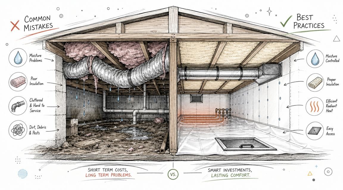
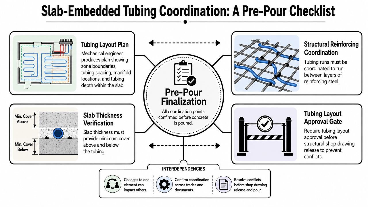
Slab-Embedded Tubing Coordination a Pre-Pour Checklist
Slab-embedded tubing is where coordination maturity gets tested. Once concrete is poured, the design window closes. That's why the review sequence matters as much as the design itself.
The Pennsylvania Housing Research Center notes that system performance depends heavily on the floor assembly's thermal resistance and that the design must drive heat upward through suitable flooring selection and proper insulation below the slab, as outlined in PHRC guidance on radiant floor assemblies. In practice, that means you're not coordinating tubing in isolation. You're coordinating a heat-transfer assembly.
The pre-pour gate has to be explicit
On disciplined projects, the tubing layout doesn't move informally from engineer to installer. It passes a formal gate before structural shop drawing release.
That gate should confirm:
- Zone boundaries are fixed
- Tubing spacing is shown
- Supply and return manifold locations are locked
- Tubing depth within the slab assembly is defined
- Architectural floor build-up is aligned with slab geometry
- Structural has reviewed the layout against reinforcing requirements
Without that gate, teams start detailing two incompatible versions of the same slab.
Structural review can't be implied
Tubing runs between reinforcing layers, and on post-tension slabs it also has to clear tendon paths. That review can't sit in a coordination meeting note with no accountable owner. Structural needs to explicitly confirm compatibility.
A clean process usually looks like this:
| Decision item | Primary owner | Required confirmation |
|---|---|---|
| Tubing layout | Mechanical | Zones, spacing, manifolds, depth |
| Reinforcing compatibility | Structural | Clearance with rebar layers |
| Tendon conflicts on PT slabs | Structural | Explicit overlay review |
| Finish assembly alignment | Architecture | Floor build-up and elevation fit |
| Slab thickness sufficiency | Structural with Mechanical input | Cover above and below tubing |
That ownership split matters. When everyone “reviews” but nobody owns, the field becomes the final checker.
Slab thickness is not a late-stage check
This is the part teams skip because each discipline assumes someone else already covered it. Mechanical looks at tubing. Structural looks at slab strength. Architecture looks at finish elevation. The actual failure sits in the gap between those views.
The slab must be coordinated as a single assembly, not as a structural object with mechanical notes attached.
On multifamily and mixed-use work, this is where template discipline pays off. If your production checklist requires slab-depth verification before tubing layout finalization, the issue gets caught in model review. If it doesn't, you're relying on luck and memory.
Radiant Panel and Fan Coil Coordination in the Architectural Model
Above-slab hydronic systems create a different class of coordination problem. They don't threaten the pour sequence, but they do create repeated architectural conflicts that are expensive to unwind once ceilings are set.
Radiant panels need reflected ceiling plan discipline
Radiant ceiling panels need real dimensions, mounting height, and perimeter clearance in the architectural model. If they're placed too close to walls, light fixtures, diffusers, or access devices, the ceiling stops working both visually and mechanically.
This is one of those cases where a panel can fit on a generic coordination plan and still fail in a finished space. Reflected ceiling plans need the same seriousness as overhead MEP coordination. Otherwise, the panel layout gets value-engineered in the field by whoever arrives last.
Fan coils consume more plenum than the plan suggests
A recessed fan coil isn't just the box shown on the schedule. The plenum has to absorb the unit body, piping connections, insulation, valve package, access for service, and the condensate route above ceiling.
That's why the unit submittal matters before the ceiling height is locked. A placeholder family based on nominal dimensions is not enough. The body height from the approved submittal has to be checked against the actual plenum condition.
Here's the practical review sequence that keeps these units from becoming ceiling RFIs:
- Confirm unit body height: Use approved submittal dimensions, not catalog assumptions.
- Check connection side requirements: Valve package and piping orientation often change usable clearance.
- Verify return air clearance: A unit that physically fits may still fail on airflow access.
- Model condensate routing: The drain line needs slope and cannot “find space later.”
Condensate routing is often the hidden clash
Fan coil condensate is where many otherwise solid models fall apart. The line needs continuous slope to a drain or to a condensate pump. In crowded plenums, that route competes with framing, lighting, ductwork, cable tray, and sprinkler mains.
If the condensate run is left for the contractor to “work out,” the permit set may look coordinated while the field condition is not. On ceiling-heavy commercial interiors, that mistake tends to trigger late rerouting and ceiling access revisions.
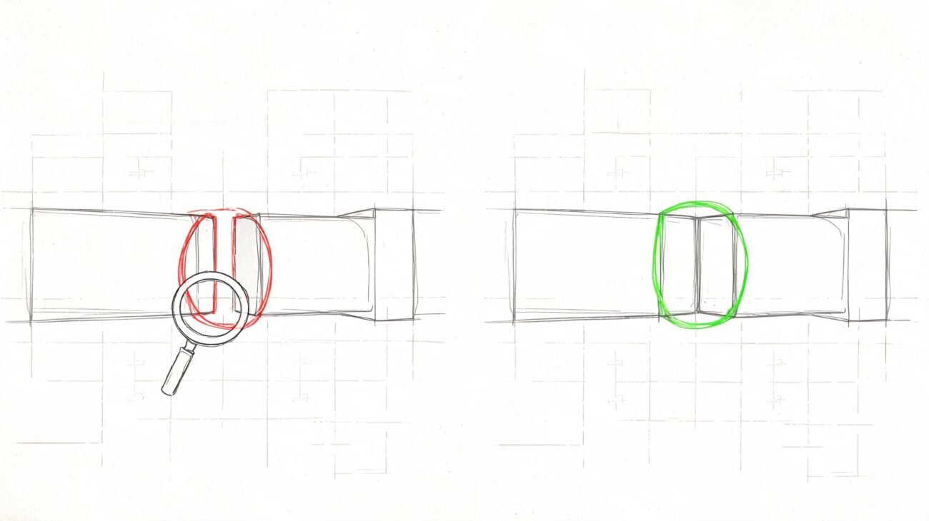
Piping Insulation and Clearance Coordination
A bare pipe model is one of the fastest ways to create false confidence on hydronic work. The clash report may come back clean, but the installed system still won't fit once insulation is added.
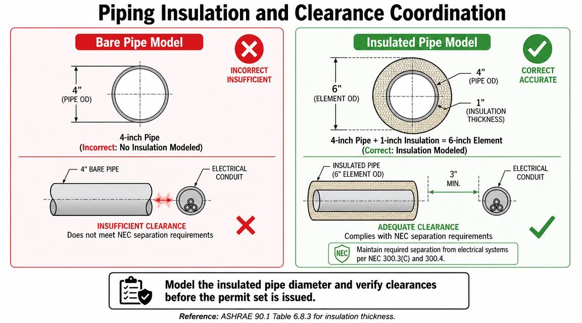
The problem gets worse on larger commercial mains. A pipe that looks manageable in plan becomes a very different object once insulation and supports are accounted for. That's why commercial radiant heating system coordination has to model the installed envelope, not the nominal pipe size.
What has to be visible in the model
The model should show:
- Pipe diameter and insulation thickness together
- Actual elevation
- Relationship to sloped plumbing lines
- Clearance from electrical equipment and conduit
- Support conditions in congested overhead areas
The author brief called out a common example, and it's a useful one in practice: a 4 to 6 inch hydronic main can become 6 to 9 inches after insulation. If the model only shows the bare pipe, the clash review is incomplete because the installable object was never tested.
Clearance is more than a geometry issue
Electrical separation checks can't be done responsibly against the uninsulated pipe. The installed diameter matters. So do support locations. In dense corridors and mechanical distribution zones, trapeze hangers often become the primary conflict point because they need structure where other systems also want space.
A simple QA table catches a lot of this before issuance:
| Check | Bad model behavior | Required correction |
|---|---|---|
| Pipe size | Bare nominal pipe only | Add insulation thickness |
| Elevation | Generic routing | Match actual install elevation |
| Electrical adjacency | Quick visual review | Verify clearance using insulated diameter |
| Support strategy | Ignored until field install | Model or reserve hanger space in congested areas |
Production check: Run clash detection only after insulation is visible on all hydronic piping types. Anything earlier is a draft, not a coordination review.
Energy Code Compliance for Permit Sets
A coordinated model still fails if the permit set doesn't document code compliance clearly. Plan reviewers don't infer intent. If the drawings don't show the required information, the set comes back.
Hydronic permit documentation usually breaks down in schedules, insulation notes, and controls language. These aren't glamorous issues, but they're some of the most preventable comments in review.
Put the code items where the reviewer expects them
For hydronic systems, the drawings should clearly document:
- Boiler efficiency: The mechanical equipment schedule should show the applicable efficiency rating.
- Piping insulation: The insulation specification should reference the applicable code table for minimum thickness.
- Hydronic controls: The sequence should identify required control strategies such as outdoor reset where applicable.
ASHRAE 90.1 is usually the reference point, but the key production lesson is about placement. Don't bury compliance in a spec section and assume the permit reviewer will chase it down. Put it on the mechanical drawings, in the schedule, and in the controls notes where it can be verified quickly.
A good internal standard is to build these fields directly into your energy code compliance drawing workflow. If code data depends on a late manual pass, it will eventually be missed.
Low-temperature operation changes the controls conversation
Hydronic systems can take 2 to 8 hours to respond to temperature changes because of thermal mass, which makes them a poor fit for spaces that need fast setback recovery, according to Messana's discussion of radiant heating response time. That matters on permit sets because controls should reflect how the system behaves.
If the project uses low-temperature heat sources such as heat pumps, the controls narrative needs to align with that operating reality. A sequence written like a fast-response air system can be technically clean on paper and still produce occupant complaints later.
Permit sets need production discipline, not cleanup passes
The strongest teams don't “finish the code notes” at the end. They template them. They create schedule fields for efficiency data. They standardize insulation note placement. They require controls references before issue.
That's how permitting stops being a scramble and starts becoming predictable.
Common Coordination Failures and How to Prevent Them
Most hydronic coordination failures repeat. They aren't mysterious, and they usually aren't caused by lack of engineering knowledge. They happen because the production workflow allowed a critical decision to stay informal for too long.
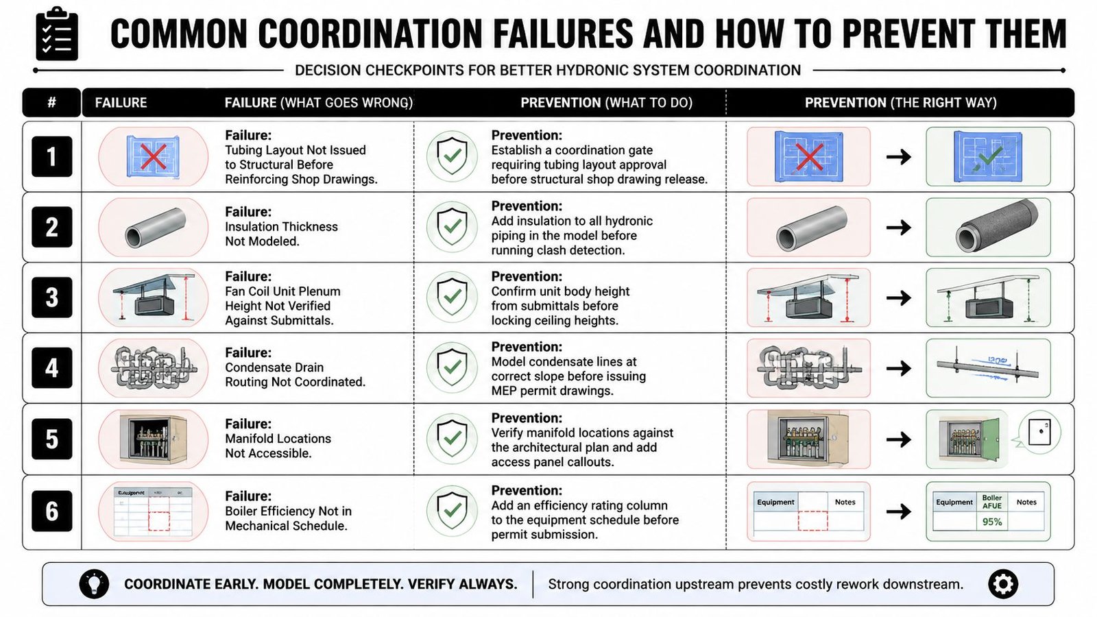
The repeat offenders
- Tubing layout reaches structural too late: Require tubing layout approval before reinforcing shop drawings are released.
- Insulation never gets modeled: Add insulation to hydronic piping before clash detection, not after.
- Fan coil plenum fit is assumed: Check approved submittal height before ceiling heights are locked.
- Condensate routing is left schematic: Model it at slope before permit issue.
- Manifolds land in inaccessible walls: Coordinate access panels and chase depth with architecture.
- Equipment schedules miss efficiency fields: Build the efficiency column into the standard template.
The prevention method is always process-based
The fix usually isn't “coordinate harder.” The fix is to create gates, ownership, and template controls that force the right information into the model at the right time.
Here's the practical pattern:
- Create a decision checkpoint
- Assign one owner
- Tie the check to a deliverable
- Don't let downstream work proceed without it
That's how RFIs get prevented instead of documented.
Mature delivery teams don't rely on heroic coordinators. They rely on repeatable checkpoints that catch the same failure before it reappears.
From Coordination Chaos to Predictable Delivery
Radiant hydronic floor heating systems are not risky in themselves. Unstructured delivery is risky. When teams treat hydronic work as a model-content and decision-sequencing problem, the system becomes far more predictable to document, coordinate, permit, and build.
That's a significant shift. You stop treating every hydronic project like a custom coordination emergency. You build repeatable review gates for slab assemblies, manifold access, insulated piping clearance, plenum fit, condensate routing, and code documentation. Then the model starts protecting the job instead of just describing it.
For firms producing commercial and multifamily permit sets, that kind of production maturity protects margins just as much as technical accuracy does.
If your team is dealing with coordination-heavy MEP permit sets and wants a more reliable production system behind them, BIM Heroes can help with MEP coordination support. Reach out if you want practical help building stronger hydronic workflows, QA checkpoints, and model standards that reduce RFIs before they start.
Category: MEP Engineering