


A coordinated piping model can look complete on screen and still leave a fabrication shop asking basic questions. The shop doesn't build from a full model alone. It builds from pipe spool drawings, piece-by-piece production documents that show how to cut, fit, weld, inspect, and identify each prefabricated assembly. A strong spool drawing turns coordinated geometry into a practical cut list and weld map, with nothing left for the shop to guess. This guide covers the drawing, common symbols, isometric dimensions, BOM content, spool numbering, and the QA checks that protect fabrication and installation schedules.
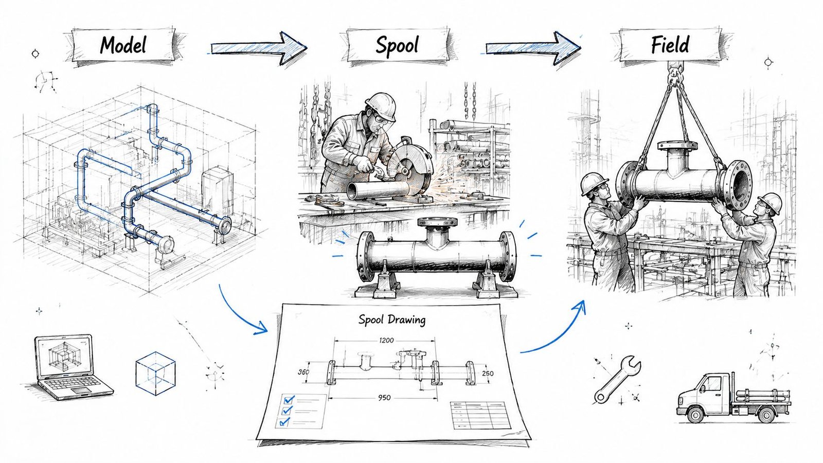
How a Spool Drawing Guides the Shop From Model to Field
A coordinated piping model is the source geometry, but the spool drawing is the production document. Detailers divide the modeled piping system into smaller shop-built assemblies, then issue a drawing for each spool with its dimensions, fittings, weld points, material information, and field connection points. The fabricator cuts and assembles from that sheet, while the field crew uses the spool number and continuation references to place it correctly.
That handoff works only when the drawing reflects the approved model and the project's fabrication rules. A useful shop drawing example should make the relationship clear: model geometry becomes a controlled package for fabrication, inspection, delivery, and erection.
Practical rule: If a fabricator has to open the model, calculate a missing length, or infer a field weld, the spool package isn't finished.
You'll leave this guide with a working reference for pipe spool drawings, including what common symbols mean, which dimensions matter, how the bill of materials, or BOM, supports procurement, and why a consistent spool number protects field sequencing.
What a Pipe Spool Drawing Actually Is
A pipe spool drawing is a detailed, usually isometric pipe drawing, of one fabricatable section of piping. A spool might include straight pipe, fittings, flanges, valves, and welded or mechanical joints assembled in the shop before the completed section ships to the field. The drawing typically identifies exact dimensions, cut lengths, fitting locations, weld numbers, materials, and bill-of-material data. Fabrication references commonly divide the sheet into graphics, BOM, and title-block areas, giving the shop both the picture and the production data in one place. A fabrication reference for stainless steel pipe spools describes this production-oriented format and the role of spools in shop fabrication and installation sequencing.
The workflow is straightforward. The piping model or project isometric is broken into manageable assemblies, each with shop welds and field-weld boundaries defined by the project team. A spool drawing is more focused than a general arrangement drawing, and it isolates one buildable piece rather than showing the entire system.
Commercial mechanical, HVAC hydronic, and plumbing work follows the project specifications and applicable construction requirements. Process and industrial piping can involve more specialized engineering and fabrication codes, including ASME B31 families, so a commercial MEP drawing set shouldn't be treated as a universal process-piping standard. The ASME B31 committee reference is a suitable starting point when a project requires that specialized code framework.
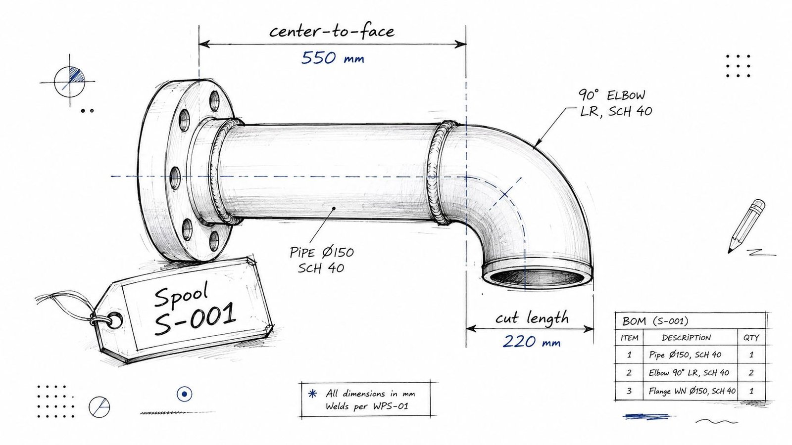
Common Spool Drawing Symbols and Conventions
Symbols let a detailer communicate routing and fabrication intent without filling the sheet with prose. They also let a shop supervisor scan the drawing quickly before releasing material to the floor.
The table below covers common conventions, not a universal symbol library:
| Common symbol or callout | Typical meaning |
|---|---|
| Elbow | Changes the direction of the pipe run. The drawing should make orientation and angle clear. |
| Tee | Creates a branch connection from the main run. Branch location and orientation matter for fit-up. |
| Reducer | Changes pipe size. The callout should identify the transition and its orientation. |
| Valve | Shows the valve location and connection arrangement. Access and flow direction may require project-specific notes. |
| Flange | Identifies a flanged connection and the face or bolt-hole orientation that controls field assembly. |
| Welded joint | Indicates a welded connection or weld location, subject to the project's weld numbering and procedure requirements. |
| Threaded joint | Identifies a threaded connection where the project permits that joint type. |
| Grooved joint | Shows a grooved mechanical connection, often used where the specified system and manufacturer requirements allow it. |
| Weld point or weld number | Links the graphic location to the weld map, inspection record, or quality documentation. |
| North arrow | Establishes drawing orientation and helps the field crew relate the spool to the coordinated layout. |
| Line and spec callout | Connects the spool to the piping line, service, material, or project specification. |
Symbol sets vary by fabricator, standard, software template, and project specification. The drawing legend and approved project spec always override a generic reference list. Before quoting, cutting, or installing from a sheet, read the legend, title block, revision status, and any fabrication notes.
Isometric Dimensions and What Actually Gets Measured
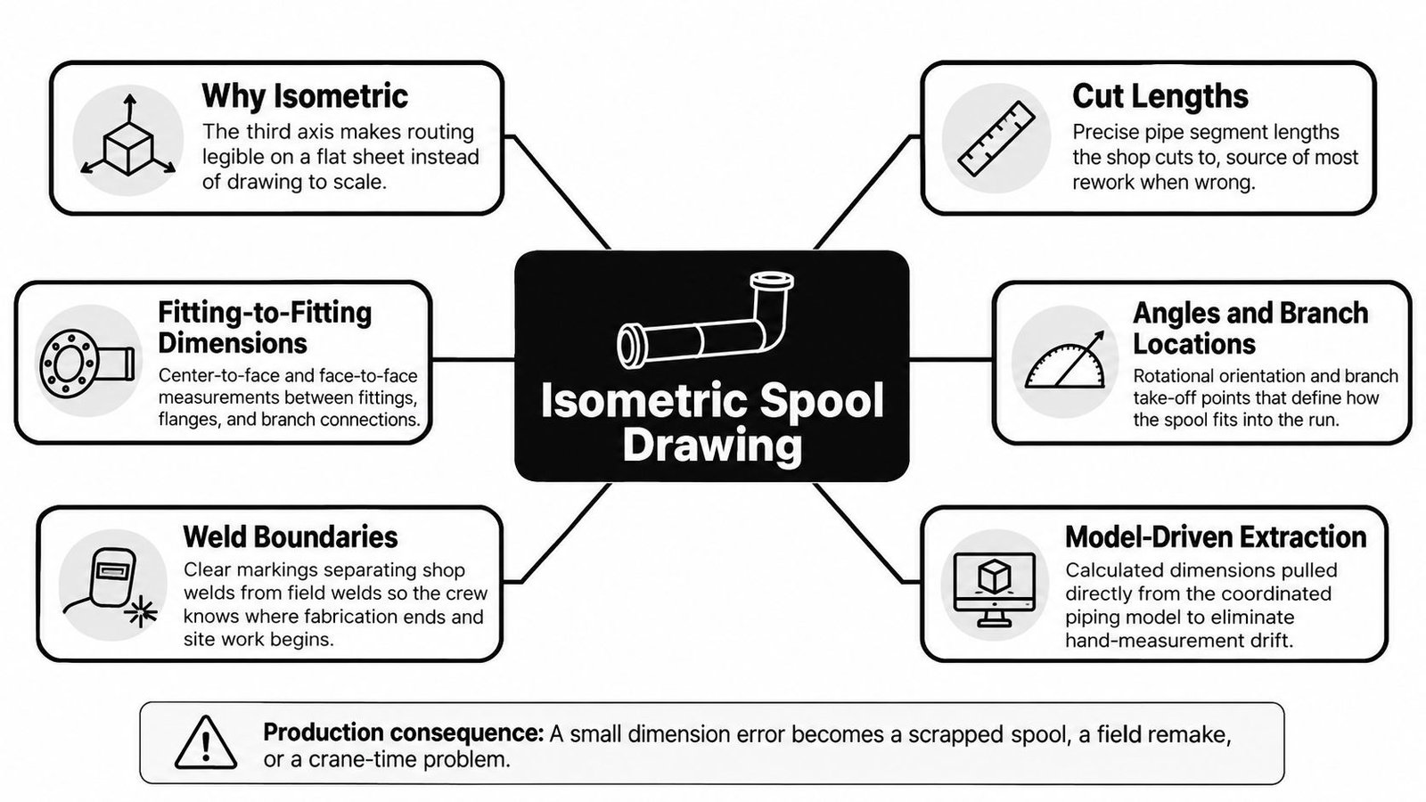
Spool drawings use an isometric view because it shows horizontal and vertical routing together on a flat sheet. It's a three-dimensional representation, but it isn't a scale drawing. The shop must use the written dimensions, coordinates, notes, and schedules, not measure the printed line with a ruler.
The dimensioning system normally communicates how each component relates to the next. At minimum, a fabrication-ready sheet should address:
- Center-to-center dimensions, between pipe centers or connected components.
- Center-to-face dimensions, from a pipe centerline to a flange face or fitting face.
- Face-to-face dimensions, where two connection faces control assembly.
- Calculated cut lengths, based on design dimensions minus fitting takeouts and required gaps.
- Angles and roll orientation, which determine whether the spool arrives in the correct rotational position.
- Branch locations and flange orientation, including bolt-hole direction where required.
- Spool boundaries, separating shop welds from field welds and continuation points.
A plumbing isometric drawing reference is useful for understanding how the three-dimensional route is communicated on a two-dimensional sheet. The important production distinction is that the shop cuts to the listed values. A wrong cut length can scrap material, while a misplaced branch or rotated flange can force field cutting, re-welding, shimming, or alignment work.
Tolerances must follow the project's dimensional-control rules. One fabrication specification states that prefabricated spool linear tolerances are not accumulative, with closer tolerances identified directly on the fabrication isometric when needed. For offshore prefabricated spools, the same specification emphasizes 100% dimensional control, showing why the drawing must identify critical fit-up points rather than relying on overall length alone. The project piping fabrication specification provides that control context.
The Bill of Materials and Why It Has to Match the Drawing
The bill of materials, or BOM, is the component inventory for one spool. It supports the shop floor and procurement team at the same time, so it can't be treated as a separate administrative list.
A useful BOM generally identifies:
- Pipe, including size, applicable material or line specification, and required length.
- Fittings, such as elbows, tees, reducers, and branch components.
- Flanges, with identifiers that correspond to the drawing and project requirements.
- Gaskets and bolts, when they're included in the spool or connection package.
- Valves and specialty items, with tags or identifiers that connect them to the model and drawing.
- Quantities and item marks, so the material group can issue and track components.
The drawing tells the fabricator where each item goes. The BOM tells the material group what must be available before assembly starts. If someone builds the list manually after the drawing is complete, the two documents can drift when a fitting changes, a branch moves, or a spool boundary is revised.
Before releasing a BOM to procurement, check that every item mark appears on the drawing, quantities match the modeled assembly, cut lengths reflect fitting takeouts and gaps, and revisions update both the sheet and schedule. For commercial plumbing shop drawings, this same discipline helps connect fabrication packages to risers, equipment rooms, and congested ceiling zones.
Model-driven extraction is the stronger workflow because the drawing and BOM come from the same coordinated data. Modern fabrication guidance notes that extracting spools directly from a 3D model can reduce drafting-related errors by roughly 80% according to this spool fabrication reference. The number is project- and workflow-dependent, but the underlying principle is practical: fewer manual redraws mean fewer opportunities for the list and the sheet to disagree.
Spool Numbering for Fabrication, Delivery, and Field Install
Every spool needs a unique spool number or tag that follows it through fabrication, inspection, shipping, and installation. The identifier links the drawing to the weld map, material issue, shop status, delivery package, and field location.
A numbering scheme might combine a line number with a spool index, add an area or floor prefix, or use another project-approved structure. No single convention is universal. What matters is that the rules are documented, readable, and applied consistently across models, sheets, BOMs, labels, packing lists, and field reports.
The shop can use the tag to track cutting, fitting, welding, dimensional checks, examination, coating, and dispatch. The logistics team can group spools by area or installation sequence. The field crew can identify which piece belongs at a particular riser, equipment connection, or mechanical-room route without opening the full model.
In just-in-time installation, inconsistent numbering creates avoidable confusion on a congested floor. A spool that arrives without a recognizable location reference can be physically correct and still become a delivery problem.
Common Spool Drawing Mistakes and the Field Problems They Cause
Most spool failures begin before fabrication. They start with a drawing that looks complete but leaves one production decision unresolved.
- Dimension errors turn into incorrect cut lengths, poor fit-up, scrap, or field modification. Fabrication references list maximum misalignment of 1.6 mm for NPS 24 and smaller and 3.2 mm for NPS 26 and larger where allowed. The same reference limits flange rotation to 1.5 mm, flange alignment deviation across any diameter to 0.75 mm, and attachment location variation to 3 mm. These values are project-dependent, so the governing specification controls. The pipe fabrication tolerance reference shows how small deviations can affect bolt-hole alignment and gasket faces.
- Missing or incorrect weld callouts can stop inspection and create uncertainty about whether a joint is shop-fabricated or field-welded. That affects the weld map, examination records, and installation release.
- A BOM that doesn't match the drawing can leave the shop missing a valve, gasket, fitting, or pipe length. Procurement then works from the wrong requirement, and the correction arrives after labor has already been scheduled.
- Inconsistent spool numbering makes delivery and installation sequencing unreliable. Field crews may have the right components without knowing where they belong.
- Spooling from an uncoordinated model carries clashes into fabrication. A pipe can be dimensionally correct and still collide with structure, ductwork, cable tray, access zones, or equipment clearances. Run MEP clash detection before releasing fabrication sheets.
- Unclear field-weld boundaries leave the crew guessing where the shop's responsibility ends. That can produce unexpected site welds, access problems, RFIs, and schedule pressure.
Release check: A spool package should answer what to build, what to order, how to inspect it, where it connects, and how the field crew will recognize it.
How BIM Heroes Produces Fabrication-Ready Spool Drawings
BIM Heroes produces coordinated, fabrication-ready spool drawings and BOMs from the approved piping model, with consistent dimensions, weld references, component identifiers, and spool numbering. The production workflow is designed for contractors and fabricators that need a reliable handoff between MEP engineering, detailing, procurement, the shop, and field installation, rather than a redraw that introduces another source of truth.
For firms evaluating outsourced MEP engineering and fabrication drawings, the useful question is simple: can the delivered sheet be built from without interpretation?
If your team needs a coordinated spool package, BIM Heroes can produce fabrication-ready pipe spool drawings and model-driven BOMs for mechanical and plumbing workflows. Book a call to share your model, standards, and fabrication requirements, and discuss the right production approach for the project.