Meta description: Common crawl space HVAC extension mistakes often start with the wrong envelope strategy, poor duct routing, weak moisture control, and missed coordination. Learn what fails, what works, and how to prevent costly rework.
Category: MEP Engineering
Heating crawl space work gets framed too superficially. Someone wants warmer floors, freeze protection, or a quick duct extension, and the discussion jumps straight to adding supply air or setting equipment below the floor.
That's usually the wrong starting point.
Most failures in crawl space HVAC happen because the team treats the crawl space like leftover volume instead of a designed assembly. The result is familiar: wet insulation, sweating ducts, noisy systems, field reroutes around piers and drains, inspection trouble, and a mechanical layout that never performs the way it looked on paper.
The Hidden Risks of Crawl Space HVAC Extensions
A crawl space HVAC extension looks minor in plan view. In the field, it often becomes one of the easiest ways to bake long-term problems into a building.
The common assumption is that heating crawl space areas is just a matter of sending some conditioned air below the floor. That misses key failure points. In many projects, the problem isn't lack of heat. It's air leakage, poor insulation, and unmanaged moisture. As noted in this discussion of whether an uninsulated crawl space increases energy bills, proper insulation can cut heating and cooling expenses by up to 20%.
That distinction matters in production. If the team solves the wrong problem first, every later decision gets worse. Duct sizing gets skewed, equipment placement becomes reactive, and trades start making field adjustments that no one priced, modeled, or reviewed.
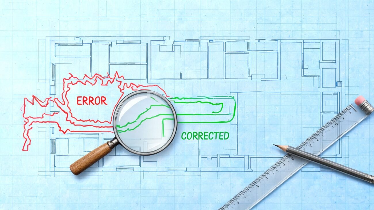
A disciplined HVAC duct layout drawing workflow prevents most of that. It forces the project to answer the questions that usually get skipped: Is the crawl space inside the envelope or outside it? Where is the vapor control layer? What routing survives the structural grid? Where will service access work?
Practical rule: If the crawl space strategy isn't locked before duct layout begins, the HVAC design is already at risk.
Good crawl space work protects more than comfort. It protects schedule, inspection outcomes, and margin. The teams that treat it as a coordination problem, not a patch job, avoid most of the expensive surprises.
Conditioned vs Unconditioned The First Design Checkpoint
Before any branch run is drawn, the team needs one documented decision. Is this a conditioned crawl space or an unconditioned crawl space?
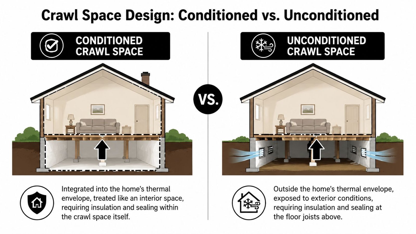
That choice changes the mechanical design, the insulation location, the vapor strategy, and the code path.
What changes between the two
In an unconditioned crawl space, the thermal boundary is typically at the floor above. The crawl space is treated as outside the conditioned envelope, so ducts and equipment below the floor are exposed to harsher temperature and humidity conditions.
In a conditioned crawl space, the crawl space becomes part of the building enclosure. The insulation line moves to the crawl-space walls, vents are sealed, and the area is treated as semi-conditioned space.
Building Science Corporation notes that conditioned crawl spaces outperform vented crawl spaces in safety, health, comfort, durability, and energy use, and describes the proper mechanism as supplying a small amount of conditioned air from the home's HVAC system so the crawl space becomes part of the envelope in its conditioned crawlspace construction guidance.
Why teams get this wrong
The failure usually isn't technical ignorance. It's a documentation gap.
Architectural sheets may show one insulation concept. Mechanical sheets may assume another. Then the owner, builder, or weatherization scope changes the crawl space strategy midstream, but nobody updates the duct insulation assumptions, equipment location, or access clearances. The field crew inherits a mismatch.
A quick comparison helps:
| Crawl space type | Thermal boundary | Typical HVAC implication |
|---|---|---|
| Conditioned | Crawl-space walls | Ducts operate closer to indoor conditions |
| Unconditioned | Floor above crawl space | Ducts and equipment need stronger protection from heat loss, humidity, and condensation |
The crawl space type is not a minor note. It's the design checkpoint that decides whether the rest of the HVAC documents are valid.
For permit sets and coordination models, this decision should be visible, not implied. If the team has to infer it from scattered notes, it will get missed.
Mistakes 1 & 2 Underinsulating Ducts and Ignoring Moisture
A crawl space HVAC failure often starts long before startup. The structural set leaves a tight beam pocket, plumbing drops into the only clean duct route, and mechanical shifts the run on site. What gets installed may still connect, but the insulation thickness, vapor control, and support details no longer match the conditions around the duct.
Underinsulated ducts lose heat fast in real crawl spaces
On paper, a short branch run under the floor can look harmless. In the field, that same run may sit below a cold subfloor, beside a wet soil surface, or hard against a rim area with air leakage. If the duct insulation was selected before the crawl space type, enclosure details, and final routing were fully coordinated, the delivered air temperature at the register will miss the design intent.
This problem shows up often on late design changes. A team extends heat to solve a comfort complaint, but nobody revisits the duct jacket, support spacing, hanger compression, or whether the route still fits without being pinched around framing and piping. A sound HVAC load calculation workflow only holds up if the installed distribution path sees the same conditions assumed in design.
The mistake is rarely just "not enough insulation." The bigger issue is that the insulation requirement was never coordinated across architectural enclosure notes, structural clearances, and the final MEP layout.
Moisture problems start with missing coordination, not just missing materials
Moisture damage in crawl spaces is usually treated as a maintenance issue. In practice, it is often a scope-gap issue.
A dirt floor, exposed foundation wall, disconnected vapor retarder at a pier, low duct insulation value, and a condensate line routed without a reliable discharge point can all exist on the same project because each item lives on a different sheet or trade package. No single installer owns the whole moisture path unless the design team makes that responsibility clear.
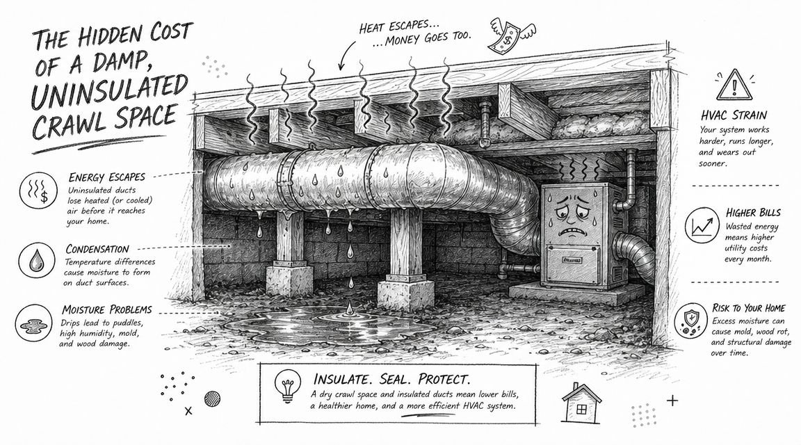
One cited estimate states that a 1,000 sq. ft. dirt crawl space can emit up to 15 gallons of water vapor per day, and when warm, moist air meets cold surfaces, condensation forms on ducts, framing, and other components, creating conditions that support mold, wood rot, and pests, as explained in this overview of how heat affects your crawl space.
Condensation on duct jackets is a warning sign. So is wet insulation, rusting straps, microbial growth at boots, or a supply trunk hung too low over damp soil. By the time occupants notice musty air upstairs, the crawl space has usually been wet for a while.
What holds up on actual projects
The fix follows a sequence.
- Set the enclosure strategy before detailing ducts: If the crawl space is outside the thermal boundary, treat duct insulation and vapor exposure accordingly. If it is inside, verify that the wall, floor, and air-sealing details support that assumption.
- Coordinate vapor control with structure and plumbing: Ground covers fail at columns, grade steps, cleanouts, and drain penetrations when those details are left to the field.
- Protect the duct insulation after routing is finalized: Crushed insulation at hangers, tight bends around beams, and last-minute offsets around waste lines reduce performance quickly.
- Keep equipment and controls out of wet zones: Pads, stands, and accessible placement matter because service technicians need dry access to keep the system operating as designed.
- Review condensate disposal early: A good HVAC layout still fails if the drain line has no practical slope, trap, protection, or discharge location.
Wet crawl spaces are enclosure and coordination problems before they are heating problems.
Teams that skip these checks end up trying to solve vapor drive and condensation with warmer supply air. That adds operating cost and leaves the root cause in place.
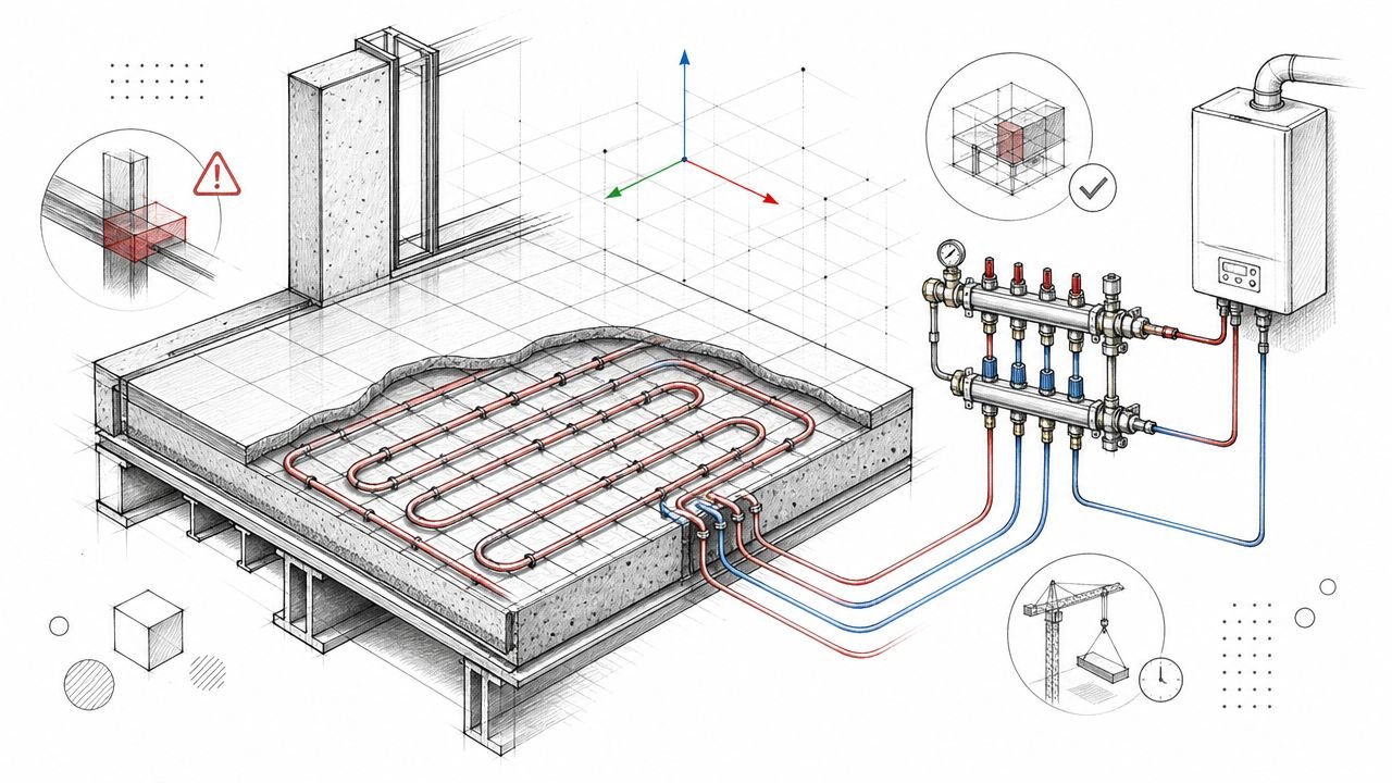
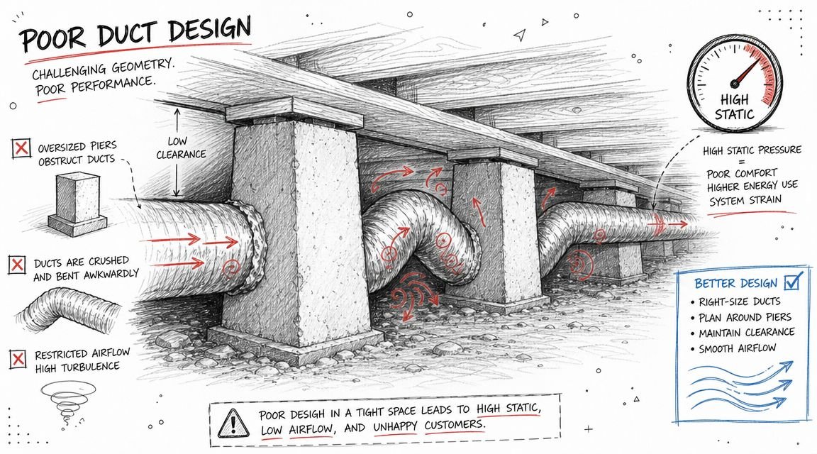
Mistakes 3 & 4 Poor Airflow and High Static Pressure
A crawl space system can be dry, insulated, and still perform badly. I see that happen when the duct layout is forced to adapt to structure and plumbing after the HVAC plan is already set.
Poor airflow and high static pressure usually come from the same production failure. The available path below the floor was assumed, not verified. Then the installer has to work around piers, girders, drains, and access zones with extra bends, compressed flex, and reduced duct sizes that were never in the original layout.
Return air gets compromised first
Supply ducts usually get protected because they are easy to spot on plan. Return paths are where coordination gaps show up first.
Once framing depth tightens, plumbing takes the clean route, or a beam blocks the intended path, the return often gets reduced to a long indirect run or a cavity path that was never detailed. The result is poor air movement back to the unit, room pressure imbalance, and air pulled from floor penetrations and adjacent voids. In a crawl-space house, that means the system can draw in air you did not intend to condition.
Three checks catch this before rough-in:
- Compare the designed return path to the actual section cut: Plan view is not enough. Verify depth, beam conflicts, and crossing points.
- Check room-to-return transfer paths: Closed doors, long hall transfers, and weak central returns show up later as comfort complaints.
- Require a balancing review before installation: Door undercuts and incidental leakage are not a return strategy.
Static pressure rises quickly in low-clearance layouts
Below-floor ductwork leaves little room for bad geometry. One extra offset around a pier may be manageable. Add a tight transition, a field-bent elbow, and a sagging flex run around plumbing, and the fan is suddenly working against far more resistance than the design assumed.
That is why crawl space HVAC problems are rarely just sizing problems. They are coordination problems that show up as airflow problems. The equipment may be acceptable on paper, but the installed system no longer matches the pressure drop the designer expected.
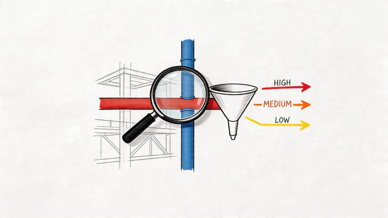
The common field causes are predictable:
| Field condition | What it does to the system |
|---|---|
| Long flex routed around obstructions | Increases friction and reduces delivered airflow |
| Crushed duct at hangers or clearances | Adds pressure drop and noise |
| Abrupt size changes to squeeze past framing | Raises static pressure and hurts balancing |
| Extra elbows added during installation | Pushes the fan outside its usable range |
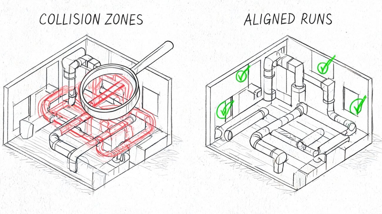
Better results come from stricter routing, not more improvisation
The best crawl space duct layouts are the ones with fewer decisions left to the field crew. Main trunks need a protected route. Fittings need to be shown realistically. Return paths need to be intentional. If the model shows a clean line but ignores girder depth, trap arms, or service clearance, the installed system will pick up resistance one compromise at a time.
If airflow depends on last-minute installer judgment at every obstruction, static pressure will usually end up too high.
Manual D still matters. So does production discipline. The HVAC layout has to be checked against real structure, real plumbing elevations, and an installation sequence that can be built in the crawl space shown on the drawings.
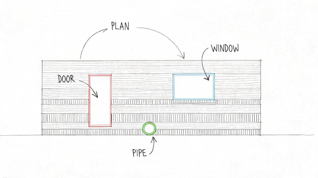
Mistake 5 Skipping MEP and Structural Coordination
Many crawl space projects lose control. The mechanical layout may be technically fine in isolation, but the crawl space never exists in isolation.
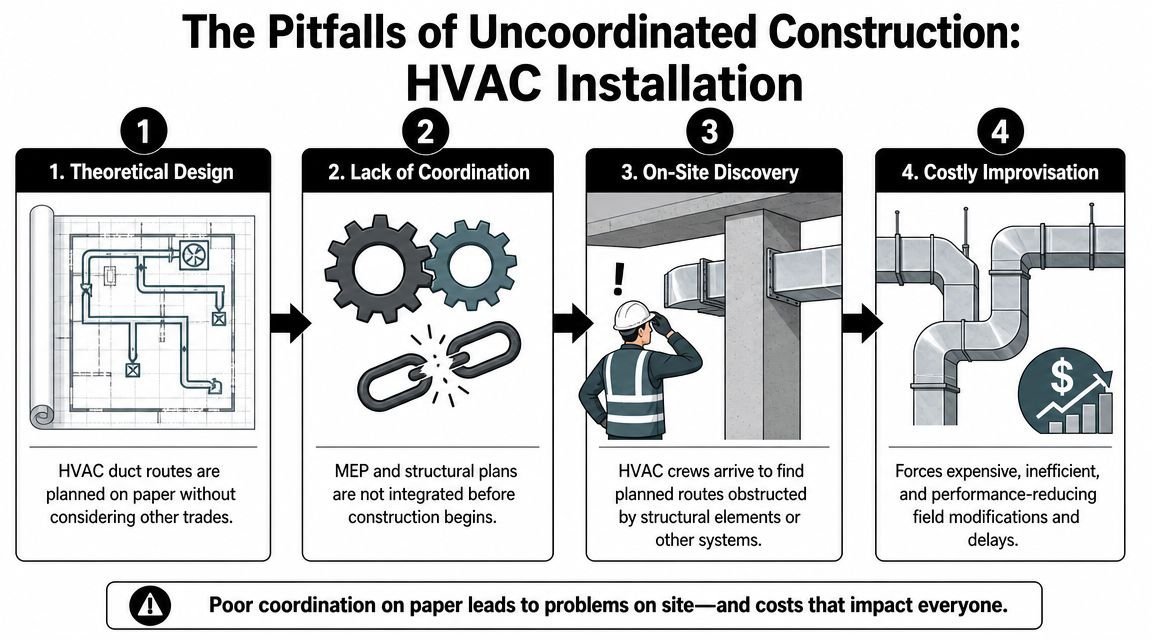
A familiar sequence goes like this. The HVAC route is drafted against a simplified floor plan. Later, the structural layout introduces piers and deeper girders in the exact zone where the trunk line wanted to run. Plumbing then claims the clean path with waste lines and traps. By the time the HVAC crew arrives, the “designed” route is gone.
What happens next is expensive, even when no change order gets written. The installer adds turns, necks down a section to squeeze past framing, drops lower than planned, and sacrifices access to get the job closed in. The system is now harder to service and more restrictive than anyone calculated.
What coordination should catch before the field does
- Pier conflicts: Main trunks and branch crossings need to be checked against actual foundation geometry.
- Girder depth and duct depth: Vertical clearance in crawl spaces disappears quickly.
- Plumbing overlap: Drain routes often occupy the same band of space HVAC assumes is available.
- Access paths: The service route to equipment can be blocked long before the unit is set.
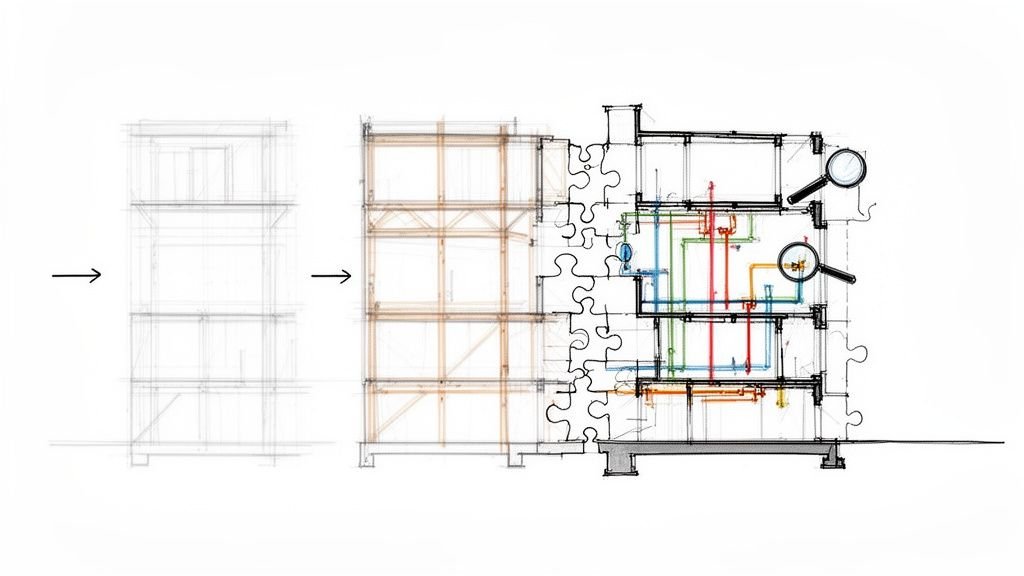
A federated model is the right tool here because crawl spaces leave very little forgiveness. A clash that might be manageable above a ceiling can become a redesign issue below a floor.
Uncoordinated crawl space work doesn't fail all at once. It fails one field compromise at a time.
That's why crawl-space coordination belongs in preconstruction and permit production, not just shop drawing cleanup.
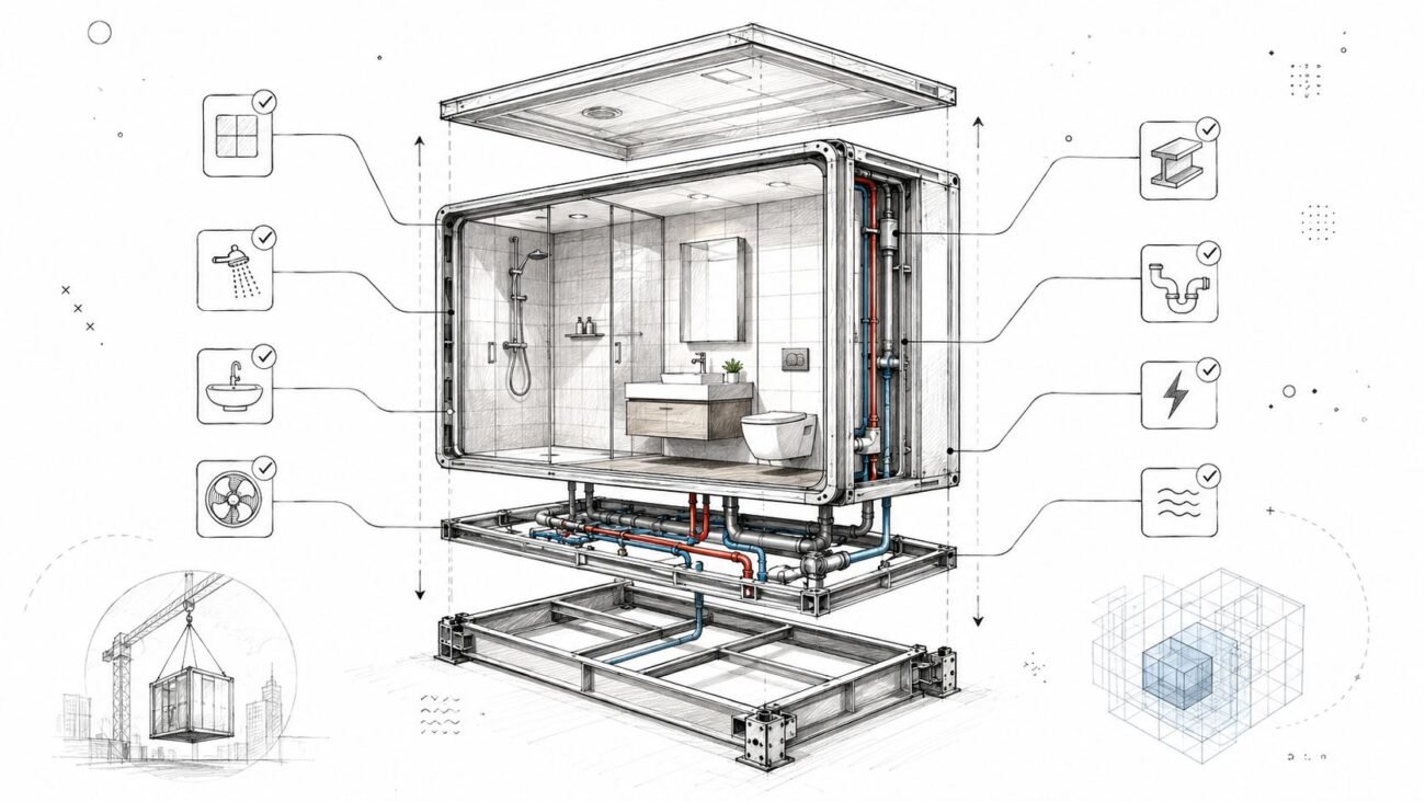
Mistake 6 Ignoring Code for Access and Clearance
The failure often shows up at inspection, not at startup. The equipment is in place, the ducts are connected, and then someone realizes the access opening is too small, the service side is blocked by a drain line, or the vapor retarder detail makes routine maintenance awkward or impossible.
That is rarely an HVAC-only mistake. It usually starts earlier, when access was treated as a note on the mechanical sheet instead of a coordinated spatial requirement shared by structural, plumbing, and MEP production.
Where teams miss the clearance check
Crawl space conditioning details affect more than enclosure performance. They also affect how a technician reaches equipment, where a service path can stay clear, and whether required working space still exists after every trade installs its scope.
I see this problem most often when the crawl space is modeled for fit but not for use. A unit may clear the framing on paper and still be a bad installation because the filter cannot be changed without crawling over piping, or because the access route narrows once the vapor barrier termination and supports are installed. A coordinated MEP workflow in Revit helps catch those conflicts before permit issue and before the field starts making compromises.
The code review needs to ask a simple question. Can the equipment be accessed, serviced, and replaced in the built condition?
A short QA check before issue for permit
Run this review before the drawings leave production:
- Verify service clearance at the actual unit orientation: Front access, coil pull, filter removal, and disconnect reach all need to work with framing, ducts, and piping in place.
- Verify the route to the equipment: The access opening and crawl path need to remain usable after structural supports, plumbing offsets, and insulation are installed.
- Verify the support condition: Show a dry, stable, maintainable base for the equipment, not a location that assumes crews will sort it out in the field.
- Verify enclosure details against access details: Ground cover, wall insulation, and air-sealing details should not block panels, doors, or service space.
- Verify fuel-fired equipment requirements if applicable: Combustion air, venting, and safety clearances need to be documented clearly, especially in tight crawl spaces.
Late fixes in a crawl space are expensive for a simple reason. There is very little room to rework anything once multiple trades have occupied the same volume.
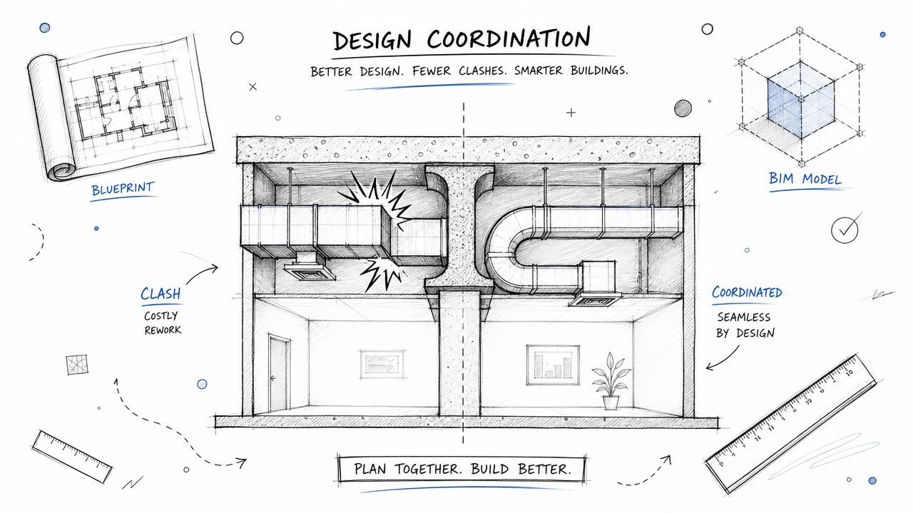
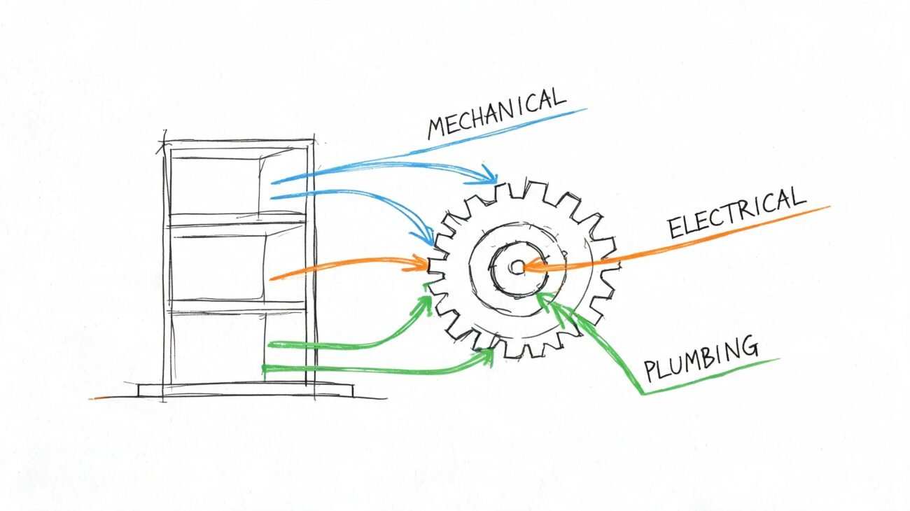
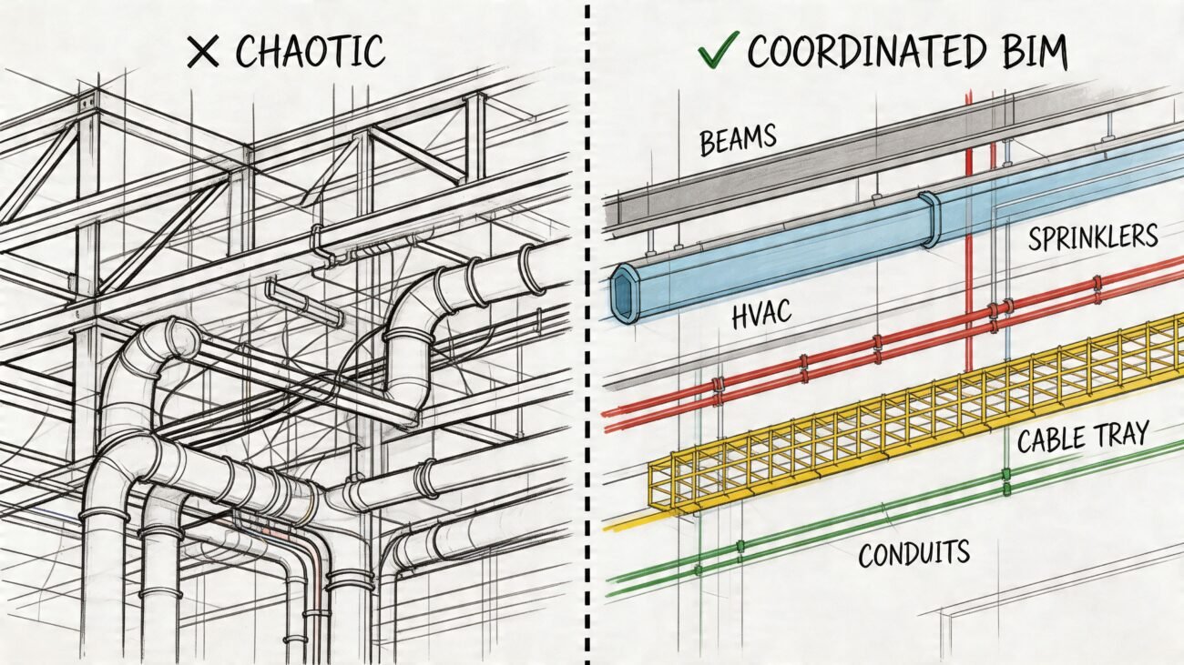
How BIM Coordination Prevents These HVAC Failures
Most crawl space HVAC problems aren't isolated drafting mistakes. They come from fragmented decisions across envelope design, structural layout, plumbing rough-in, and mechanical routing.
A federated model changes that workflow. It lets the team test whether the crawl space type matches the duct strategy, whether the duct strategy survives the pier grid, whether access remains code-compliant after plumbing is routed, and whether the details in the documents support the way the system will be built.
That's where model-based production adds real value. A coordinated MEP workflow in Revit turns crawl space HVAC from a reactive field exercise into a documented installation plan with decision checkpoints, clash review, and QA before crews mobilize.
The payoff is simple. Fewer RFIs. Fewer field improvisations. Better predictability in labor, schedule, and performance.
If your team is dealing with crawl space HVAC layouts, permit drawings, or coordination problems between structure, plumbing, and mechanical systems, BIM Heroes can support the production side with MEP coordination and construction document development. It's a practical fit for GCs, engineers, and design teams that want cleaner install-ready information, fewer field conflicts, and a more reliable path from model to build.