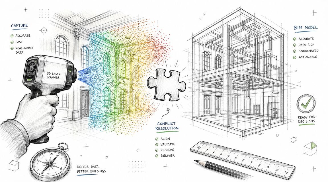
Meta description: Clean clash logs don’t guarantee coordinated MEP work. Learn the critical gaps between BIM clash detection and field-ready MEP coordination, including modeling omissions, clearance failures, sequencing issues, and field deviations.
A lot of teams are running clash detection on schedule, closing issues in Navisworks, and still getting field RFIs that stop work.
That situation isn’t unusual. It’s what happens when a team mistakes a clean clash report for a coordinated project. The report says the modeled objects no longer intersect. It doesn’t say the systems can be installed, accessed, maintained, sequenced, or built exactly as shown.
That distinction matters in clash detection MEP coordination. Most coordination failures that show up late aren’t software failures. They come from process gaps. Something wasn’t modeled. A clearance wasn’t reviewed. The install sequence was never tested. A field change never made it back into the model.
Clash detection is still one of the most useful checks in a BIM workflow. It reduces avoidable rework, and rework can account for 5-15% of total project costs in construction according to ENG BIM’s overview of BIM clash detection. But if you want fewer surprises in the ceiling, above the corridor, or inside a congested riser, the team has to think past the report.
The Clean Report Paradox
The clash log is closed. Coordination meetings are done. Trade leads sign off on routing. Then the field sends back an RFI because a valve can’t be reached, a duct can’t be lifted into place, or the pipe clears on screen but not once insulation is installed.
That’s the paradox experienced BIM managers know well. A model can be clean and still not be coordinated.
Usually, the missed issue was not an actual hard clash. It was a conflict the software was never asked or able to locate. The model did not include the actual geometry. The clearance zone was never modeled. The sequence was wrong. The installed condition drifted from the coordinated model and nobody closed the loop.
A clean clash report is a geometry result, not a constructability verdict.
That’s why teams who already know how to run BIM clash detection still see failures reach the field. The tool is doing its job. The process around it often isn’t.
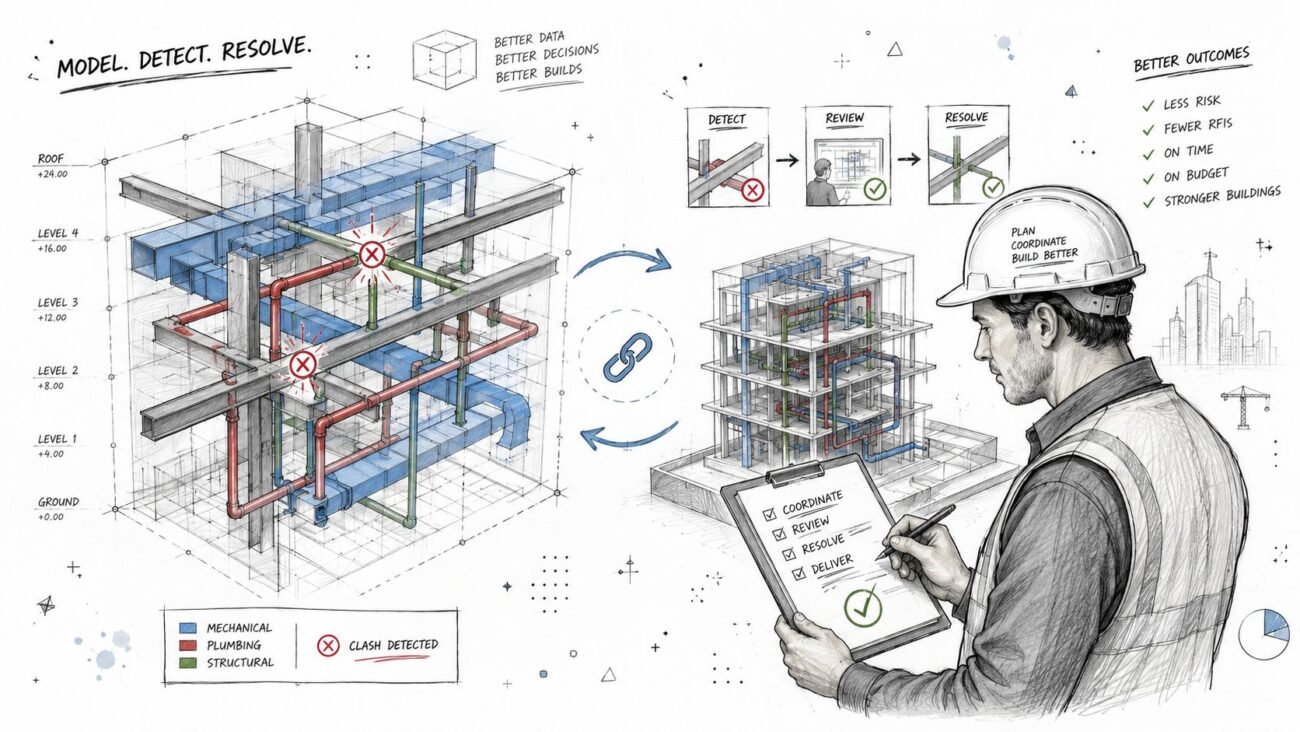
What Clash Detection Actually Does
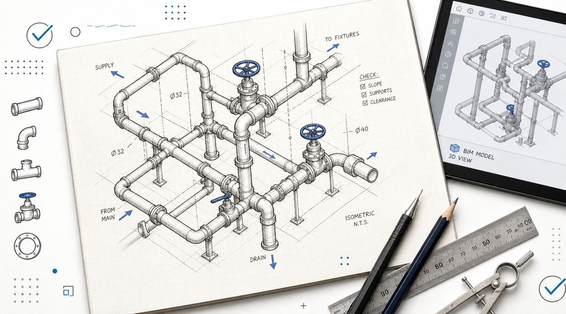
Clash detection compares modeled geometry and flags conflicts between elements in a federated model. In practice, that usually means three categories:
- Hard clashes where objects physically intersect
- Soft or clearance clashes where required spacing is breached
- Duplicate conditions where elements occupy the same location
That’s the boundary. It’s a geometric comparison tool.
What the software sees
The software works on what the team modeled, at the level of detail available, at the moment those models were last published. For reliable results, models generally need to be at LOD 300-400, and hard clash tolerances are often near zero while soft clash clearances for MEP access can range from 100-300mm, as outlined by Designing Buildings on clash detection in 3D BIM models.
If a model is thin, stale, or abstracted, the results are thin, stale, or abstracted too.
What the software does not see
Clash detection doesn’t understand maintenance intent, code interpretation, installation logic, field tolerances, or trade means and methods unless someone has translated those requirements into modeled geometry or explicit review rules.
That isn’t a flaw in Navisworks clash detection or any other platform. It is the limit of the method.
Practical rule: Treat clash detection as one QA check inside a larger BIM coordination workflow, not as proof that coordination is finished.
The Modeling Gap What Is Not Modeled Cannot Clash
The most common reason a “coordinated” model still fails in the field is simple. The conflicting geometry was never in the model.
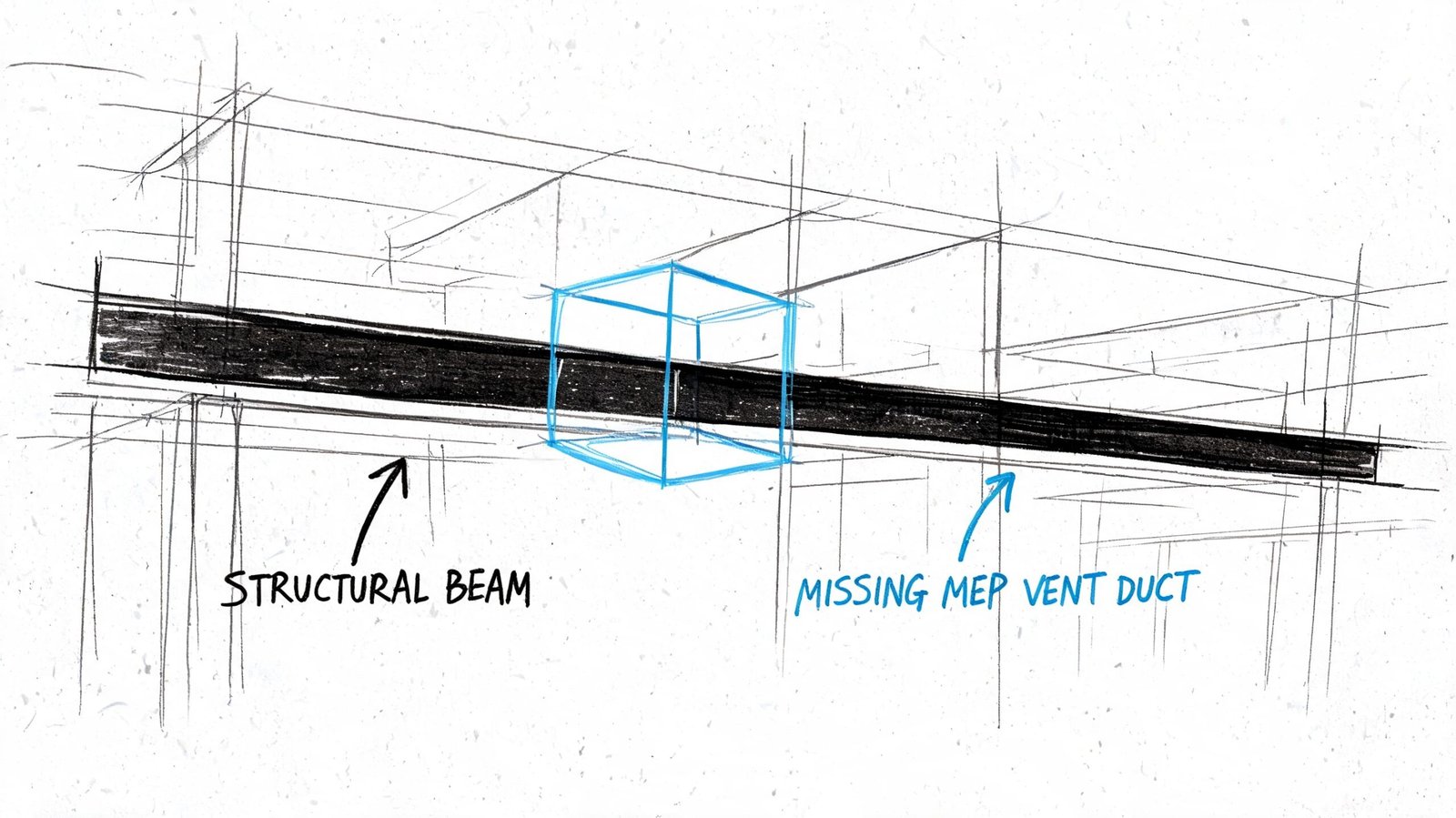
A clash test can only compare solids, tolerances, and modeled relationships. If the electrical package shows conduit as lines without diameter, if cable tray is missing true width and depth, or if supports and trapezes are omitted entirely, the software has nothing meaningful to test. The report looks cleaner than the job is in reality.
Common omissions that break MEP coordination
Some omissions show up on almost every fast-moving project:
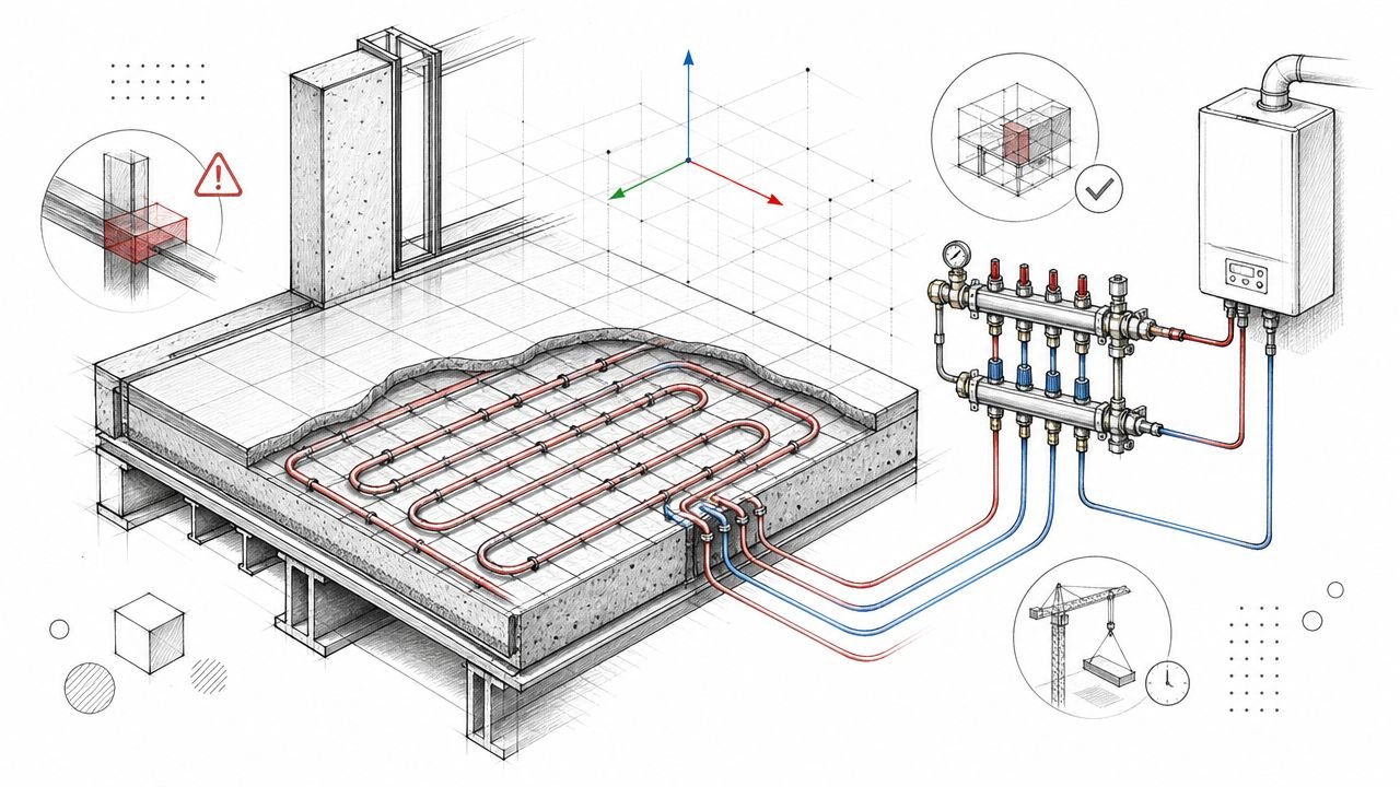
- Insulation and lining: Pipe and duct may clear at nominal size, then fail in a tight plenum once insulation thickness is added in the field.
- Hangers and supports: Main routing works on screen, but support steel collides with adjacent systems or structure.
- Seismic and sway bracing: Fire protection and mechanical systems may coordinate in final position but conflict once bracing is installed.
- Access components: Cleanouts, access doors, and service zones often go unmodeled, so nothing flags the future maintenance problem.
- Structural connection geometry: The member clears, but the stiffener, connection plate, or embed does not.
A lot of teams talk about LOD but use it loosely. If the model isn’t detailed enough for the coordination decision being made, then the issue isn’t really “LOD complete.” It’s only visually convenient. Consequently, a disciplined BIM level of detail strategy matters. Not as documentation theater, but as a precondition for trustworthy coordination.
What to check before you trust the report
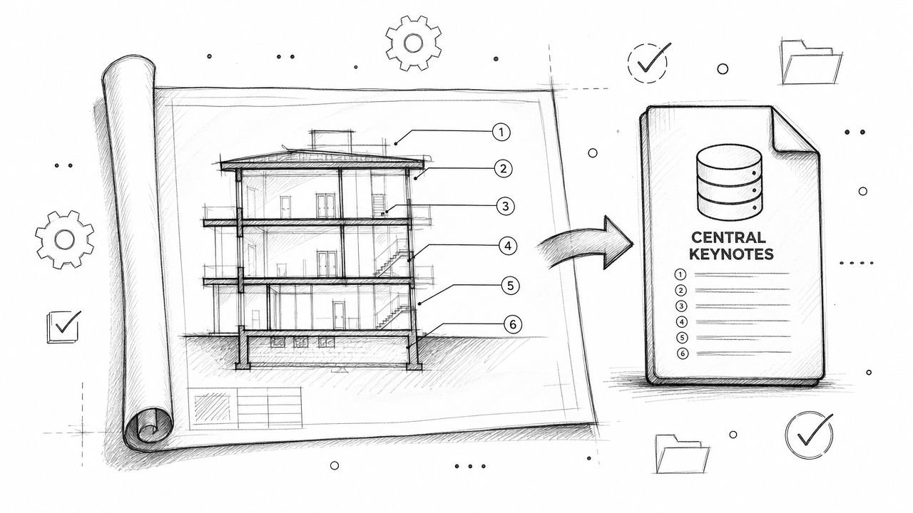
Before running major coordination cycles, audit the model for completeness, not just file delivery. A useful review looks at questions like these:
| Review item | What to verify |
|---|---|
| MEP geometry | Are ducts, pipes, trays, and conduit modeled with real geometry rather than symbolic paths? |
| Secondary elements | Are hangers, supports, and bracing included where they affect space claims? |
| Added thickness | Is insulation, lining, or enclosure thickness accounted for in congested areas? |
| Structural detail | Does the structural model include connection zones that affect routing decisions? |
When teams skip that audit, they often confuse missing geometry with successful coordination. That’s one reason field-driven rework stays stubbornly high even when teams are “doing clash detection.” In construction, rework can consume 5-15% of total project costs, and early virtual resolution is one of the core reasons BIM delivers ROI, as noted in the earlier ENG BIM reference.
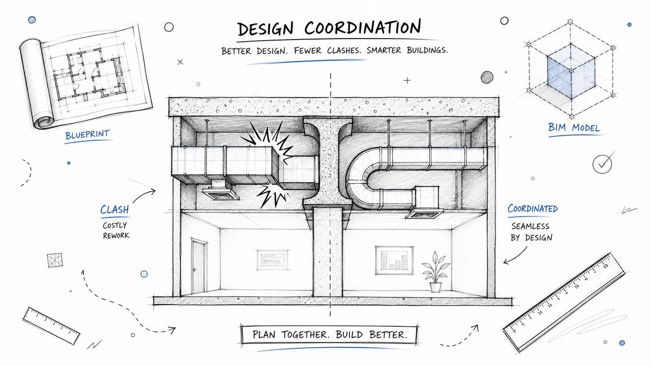
The Clearance Gap Spatially Correct But Functionally Wrong
Some of the worst coordination failures involve no hard clash at all. The systems fit. They just don’t work.
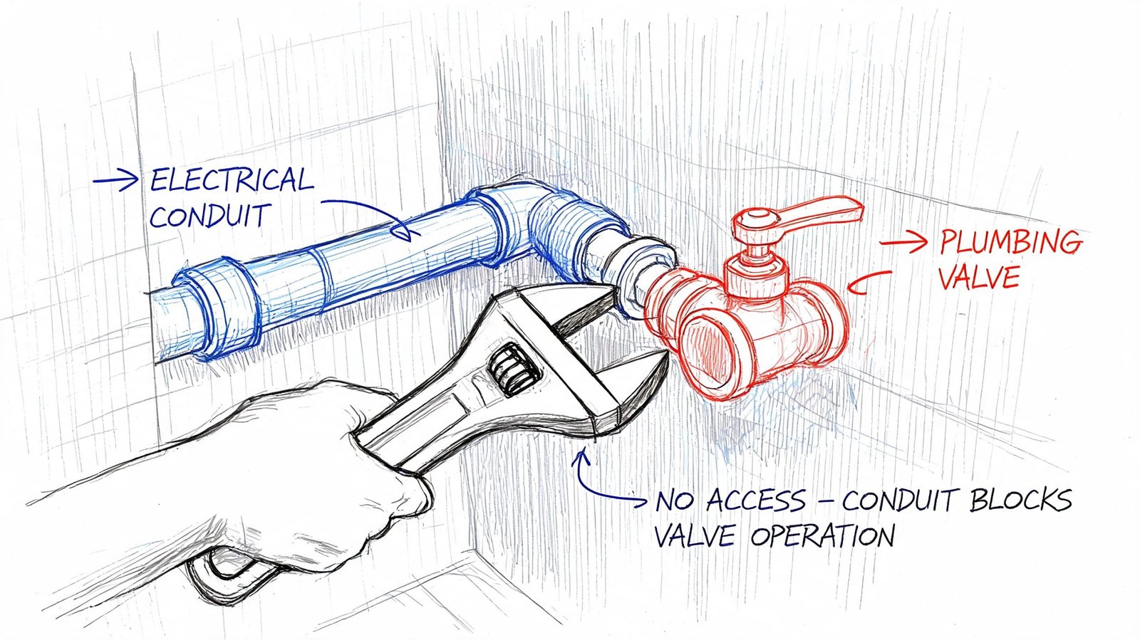
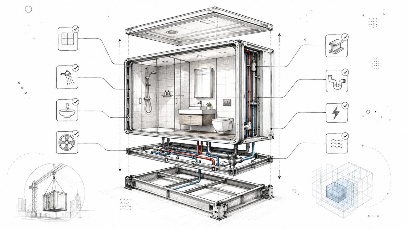
A duct can sit beside a VAV box with no modeled interference and still block access to controls. A conduit rack can clear a plumbing valve and still make the valve impossible to operate. A panelboard can fit in the room and still violate required working space because nobody modeled or reviewed the access envelope.
Clearance is not the same as empty space
Teams run into MEP clash detection limitations. Hard clash testing answers one question. Do two modeled objects overlap? Functional coordination asks different questions:
- Can a technician reach the component?
- Can the trade install it the way it’s designed?
- Can the owner maintain it after turnover?
- Does the layout respect code-required working space and operational clearance?
Those questions usually require a human review by someone who understands the system, not just the software.
A good example is plenum congestion. On paper, every service may route through the ceiling without direct intersection. In reality, once access zones, control clearances, and trade spacing are considered, the ceiling is overloaded. That’s why teams dealing with dense overhead conditions benefit from a more disciplined plenum ceiling coordination approach, not just another clash test.
Where teams usually miss it
These misses are predictable:
- Maintenance access: Filters, coil pulls, actuator access, and service panels need room that often isn’t represented in base geometry.
- Code-required working space: Electrical and life safety systems carry clearance rules that a simple hard clash test won’t capture unless the clearance zones are modeled.
- Operability: A valve handle, balancing damper, or access panel can be physically present and still be unusable.
- System relationships: Hot and cold systems, noise-sensitive spaces, and specialty equipment often need separation logic that goes beyond pure geometry.
If the review ends at “it fits,” the team hasn’t finished coordination. They’ve only finished collision checking.
What works better than tolerance alone
Teams often try to solve this by tightening or loosening Navisworks clash detection tolerances. That helps, but only to a point. Tolerance settings don’t replace judgment.
A stronger method is to separate review types:
- Run geometry clashes for hard and soft intersections.
- Run a dedicated access review with modeled clearance envelopes where critical.
- Bring in trade and facilities knowledge for equipment that has real service constraints.
- Sign off by zone, not just by issue count.
That’s the difference between clash detection vs coordination. One reports intersections. The other protects function.
The Sequencing Gap When Installation Order Creates Conflict
A coordination model shows the final installed condition. Construction doesn’t happen that way.
A large duct section may fit perfectly in the finished model, but the mechanical contractor may never be able to lift it into place once the piping rack is installed. The final geometry is valid. The install path is not.
Final position is not installation logic
Workflow and sequencing problems often arise. They’re easy to miss because nothing in a static federated model tells you who installs first, what access route is required, or which trade loses maneuvering room after another trade finishes.
Examples show up quickly:
- A prefabricated duct assembly fits at its endpoint but can’t get through the corridor or shaft opening on the way there.
- A pipe bank installs first and blocks the rigging path for the airside equipment that comes later.
- Sleeves are approved in principle, but no one coordinates them early enough against structural constraints before concrete placement.
So-called workflow clashes tied to scheduling and sequencing can contribute to 30-40% of rework costs, and prioritizing discipline hierarchies such as structure before MEP can reduce those delays, according to The CAD Room’s clash detection best practices for modern MEP projects.
What sequencing review should include
A real sequencing review is less about software and more about decisions:
- Trade order: Which systems claim space first?
- Installation access: What gets brought in assembled, and what gets built in place?
- Sleeves and embeds: What must be locked before structure advances?
- Prefab constraints: What are the actual transport and lifting limitations?
This is one of the biggest MEP coordination gaps on otherwise organized projects. Teams clear the model and never hold a serious conversation about how the coordinated layout gets built.
The Field Deviation Gap When Reality Overtakes the Model
Even a well-coordinated model starts to drift once the field takes over.
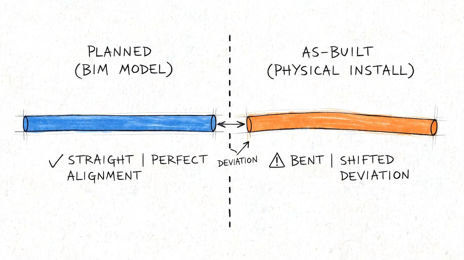
A foreman shifts a route to avoid an obstruction. A substituted fitting has different dimensions than the basis-of-design product. A late structural revision changes a support condition. None of those changes matter to the clash log unless somebody updates the model and reruns coordination.
The model freezes. The site keeps moving
“Approved for coordination” becomes dangerous language. The model represents design intent at a point in time. It is not automatically the truth of the field.
Typical drift comes from a few repeat causes:
- Material substitutions: Similar product, different geometry.
- Field reroutes: Small trade decisions that never make it back to the BIM team.
- Tolerance stacking: Minor deviations accumulate in a crowded ceiling zone.
- Late design revisions: One discipline changes after the others have mentally moved on.
Any one of those can create a new conflict inside a previously clean area.
The field doesn’t care that the model was coordinated last month. It only cares whether today’s installed work still matches it.
Why this becomes a commercial problem
When unmanaged coordination conflicts stay unresolved, they don’t just create inconvenience. They create schedule and claim exposure. Poorly managed coordination conflicts are a primary source of AEC disputes, and those disputes add an average of 17 months to project schedules and cost $33 million per incident on average, according to Bricsys on the long-run savings of BIM clash detection.
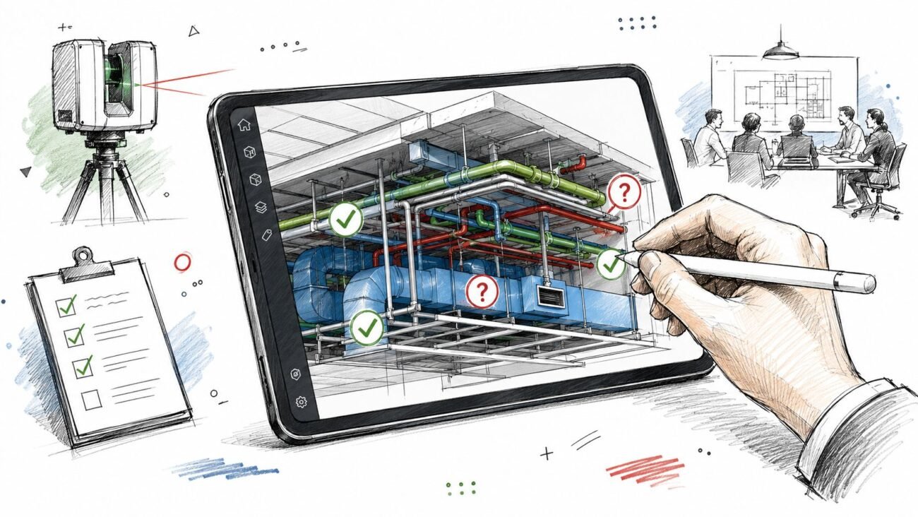
That’s why mature teams build a field verification loop into the BIM coordination workflow. They don’t assume the coordinated model stays valid on its own. They keep checking whether reality still matches the decision set the model represents.
From Clash Report to Coordinated Project A Complete Workflow
If the goal is predictable delivery, the answer isn’t more clash tests by themselves. The answer is a fuller coordination process around them.
A mature team treats clash detection as one checkpoint inside a broader QA system. That system starts before the first report and continues after the model appears clean. If you want the baseline workflow, this clash detection overview is a useful companion. What matters here is everything the report alone doesn’t close.
The workflow that actually protects margins
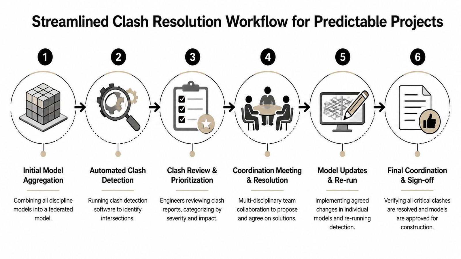
A reliable process usually includes five distinct controls.
Pre-coordination model audit
Check model completeness before running major tests. Confirm agreed LOD, real geometry, thickness allowances, and secondary elements that affect space.Clearance and access review
Review maintainability, operability, and code-related working space separately from hard clash results. This needs engineering judgment, not just issue counts.Sequencing checkpoint
Hold a dedicated meeting on installation order, access paths, sleeves, embeds, and prefab movement. Don’t bury this inside a generic clash review.Model update protocol
Define who updates the federated model after field changes, substitutions, or design revisions. If nobody owns this, the model degrades fast.Field verification loop
Compare installed work against the coordinated model at planned intervals so deviations get caught before the next trade builds on top of them.
What this changes in practice
This process changes how teams measure progress.
| Weak signal | Better signal |
|---|---|
| Clash count is down | Zone is complete, accessible, and buildable |
| Model is clean | Model is current and aligned with field conditions |
| Trades attended the meeting | Trades agreed on routing, sequence, and ownership |
| Coordination is done | Coordination is stable enough for the next decision gate |
The point isn’t to add bureaucracy. It’s to protect predictability. Teams that skip these controls often pay for it later through RFIs, field redesign, stop-start labor, and avoidable coordination meetings after installation has already started.
Field lesson: The cheapest clash to fix is the one found before procurement, before prefab, and before another trade builds around it.
Conclusion Building Beyond the Clash Report
A clean clash report means one thing. The modeled geometry doesn’t intersect under the rules you ran.
It does not mean the project is fully coordinated. It doesn’t confirm model completeness, code compliance, maintenance access, installation sequence, or field accuracy. Those gaps are predictable, and they’re manageable when the team treats clash detection as part of a disciplined coordination system instead of the whole system.
If your team keeps running clashes and still sees avoidable field conflicts, the problem is usually not the tool. It’s the workflow wrapped around it.
If you're working through coordination failures that keep slipping past the model, BIM Heroes can help you diagnose where the process is breaking down. We support firms with BIM workflows, coordination systems, and production-ready delivery frameworks that go beyond running reports. If useful, reach out for a conversation about checklists, review gates, or a cleaner MEP coordination process on a current project.