Meta description: CLT panel openings coordination BIM starts long before fabrication. Learn the workflow, schedule checkpoints, and approval process that prevent costly cutout errors in clt timber panels.
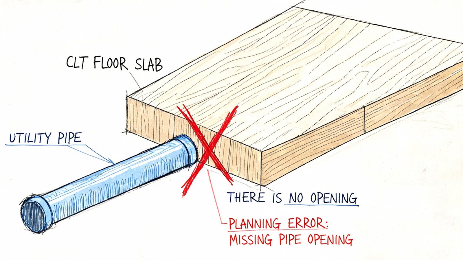
A missed opening in stud framing is usually a field problem. A missed opening in clt timber panels is a fabrication problem, a structural review problem, a finish problem, and often a schedule problem at the same time.
That's the mindset shift many teams underestimate on their first mass timber job. If a duct sleeve, drain penetration, connector pocket, or electrical recess isn't resolved before the panel goes to CNC cutting, the project team is no longer “coordinating.” It's recovering. Recovery is slower, more expensive, and far less predictable than getting the model right the first time.
For GCs, architects, structural engineers, and BIM managers, the issue isn't whether CLT works. It does. The global CLT market was valued at USD 1,024.4 million in 2023, rose to about USD 1,174.1 million in 2024, and is projected to reach USD 3,537.9 million by 2032 according to industry reporting cited by Circle Economy's CLT market summary. The issue is whether your coordination workflow is mature enough to support a prefabricated structural system.
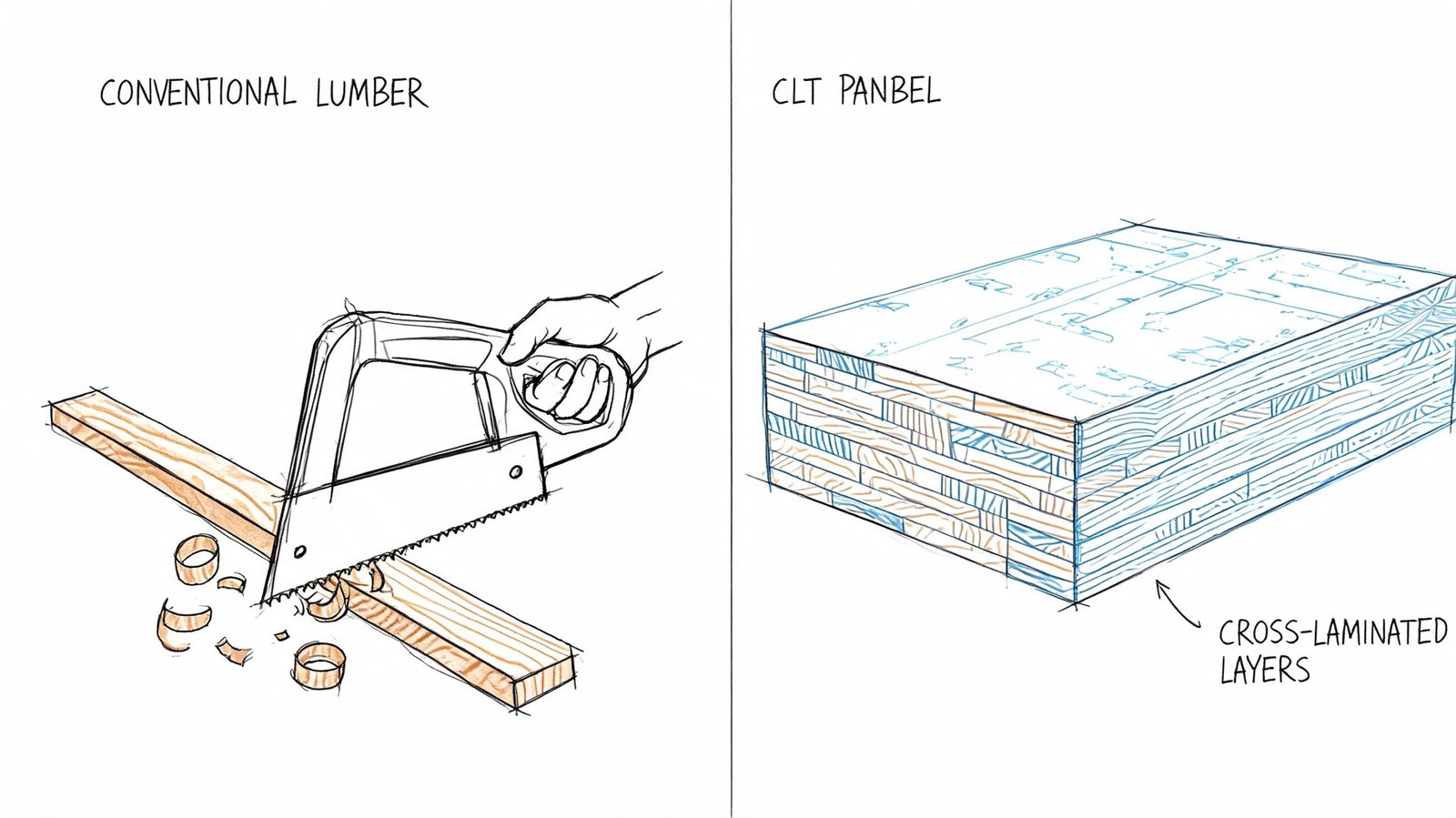
Why CLT Panels Are Not Conventional Framing
The biggest mistake on a CLT project is treating it like a wood-framed project with larger parts. It isn't.
CLT panels are prefabricated structural elements, and the product's commercial adoption has been built on standardization. The ANSI/APA PRG-320 standard defines CLT as a prefabricated engineered wood product, and North American production has been scaling quickly enough that U.S. annual production was expected to approach 2 million cubic meters per year within a decade according to the Virginia Tech Center for Forest Products Business. That scale only works because the manufacturing process depends on disciplined inputs.
CLT is structure and finish at the same time
In many projects, a CLT wall or slab isn't just carrying load. It's also the visible surface. That changes the consequence of every cut. A rough field opening doesn't just risk capacity or connection conflicts. It can also damage the finished appearance the architect was counting on.
That's one reason teams moving from conventional wood framing workflows to mass timber need a different production mindset. In conventional framing, you can often absorb a late change with labor. In CLT, late changes often collide with engineering, procurement, and fabrication at once.
Factory accuracy changes the rules
CLT is manufactured to panel-specific geometry. Openings, notches, connection pockets, and edge conditions are cut from approved shop data. Once that data is released, “we'll solve it in the field” stops being a practical strategy.
A few realities drive that:
- Panelized fabrication: CNC equipment cuts exactly what the approved model and shop drawings tell it to cut.
- Tight tolerances: CLT panel geometry is controlled tightly enough that field improvisation usually looks exactly like what it is, an after-the-fact correction.
- Long lead times: If the error is serious enough to require redesign or remake, you're not dealing with a same-day patch.
Practical rule: On a CLT job, field cutting is a contingency. It is not a coordination plan.
The planning window moves earlier
The most important operational change is timing. In conventional projects, some routing and penetration decisions can drift deeper into CDs or even site coordination. On CLT jobs, those decisions move upstream because approved fabrication data closes the window much earlier.
That doesn't make CLT risky. It makes it less forgiving. Teams that understand that early tend to protect margin. Teams that don't usually learn it through change orders.
A Complete Inventory of CLT Openings and Cutouts
Most first-time CLT teams think about openings as windows, doors, and maybe a few big floor penetrations. That's not enough. The actual list is broader, and the dangerous items are often the small ones that slip through discipline handoffs.
Architectural cutouts go beyond doors and windows
Architectural openings are the obvious category, but they aren't limited to envelope and circulation elements.
Common examples include:
- Window and door rough openings: These get the most attention, and they should.
- Stair and shaft openings: These affect panel layout, support conditions, and connection logic.
- Recessed niches and built-ins: Millwork recesses, shelving pockets, and feature wall details often require factory cutting.
- Access panels: Roof and ceiling assemblies may need planned openings for maintenance and service access.
Architects usually catch the large visible openings. Problems start when smaller design features stay in interior elevations or detail sheets and never make it into the fabrication-facing model.
Structural cutouts are easy to miss if the model is too schematic
Some of the most schedule-sensitive cuts aren't architectural at all. They're structural.
These usually include:
- Connection hardware pockets
- Bearing pockets for steel or timber support elements
- Recesses for splines, dowels, or concealed hardware
- Edge shaping tied to panel-to-panel assembly
If those items are still conceptual when MEP starts routing, the coordination model is already behind. A penetration that looks fine in plan can land directly in hardware space once the delegated design is developed.
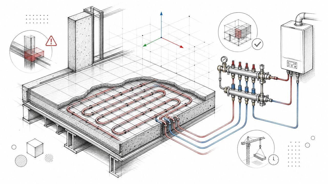
MEP penetrations create the highest coordination load
Most projects feel the pressure at this point. The count is higher, the ownership is fragmented, and service penetrations bring fire detailing into the conversation.
Typical MEP-related cutouts include:
- Plumbing stack penetrations through floor panels
- HVAC duct openings through walls and floors
- Electrical conduit sleeves and grouped pathways
- Sprinkler penetrations
- Recessed boxes and routed face pockets
The fire side matters just as much as geometry. Fire performance in CLT assemblies is heavily dependent on detailing at service penetrations, and practical questions around concealed cavities, sleeves, and reinforcement remain a major issue according to the USDA Forest Products Laboratory paper discussing CLT fire and detailing considerations.
Penetrations are not drafting items. In CLT, they are fabrication inputs and assembly decisions.
If the team inventories openings discipline by discipline, it will still miss things. The better method is panel by panel. Every panel gets a complete opening and cutout record before fabrication release.
Common Coordination Failures on CLT Projects
Most CLT problems don't start at the factory. They start in the model, usually when one discipline assumes another team will resolve something later.
MEP design lags behind panel decisions
This is the most common failure pattern. The structural team advances panel layout, the architect is pushing permit, and MEP routing is still evolving like it would on a conventional build.
That sequencing breaks down fast in CLT. If the panel geometry is moving toward shop release while duct and pipe routes are still schematic, the team has created a collision between design pace and fabrication pace.
Penetrations are located by room logic instead of panel logic
MEP teams often place openings relative to rooms, grids, or walls. Fabricators need those same openings tied to panel IDs and panel coordinates.
A penetration can be “correct” in the room and still be wrong for the panel. It may land on a joint, crowd a connector pocket, or drift into an edge condition the structural engineer won't accept. If your coordination notes still describe openings in architectural language only, the workflow isn't ready for release.
Structural restrictions stay buried in notes
Structural engineers often know where penetrations can't go. The problem is how that information gets handed off.
If no-penetration zones live only in calculations, redlines, or general notes, MEP coordination becomes guesswork. The routing team needs those restrictions visible in the model, not buried in PDFs.
The best CLT coordination models make bad decisions hard to draw.
Fire requirements arrive too late
A sleeve is not just a circle around a pipe. On CLT projects, sleeve type, fire stopping, assembly logic, and sometimes reinforcement all have to align before fabrication release.
When that information sits only on fire protection sheets or code review markups, the panel model remains incomplete. The result is an opening that may be geometrically right and still wrong for the actual assembly.
Late changes after release create the worst cost
Industry guidance is blunt on this point. Field modification of a 3-ply CLT panel is awkward, and cutting clean openings in 5-ply or thicker panels becomes dramatically harder according to mass timber field modification guidance summarized by M Moser Associates.
That's why late window shifts, relocated risers, and last-minute ceiling changes do so much damage on CLT jobs. The issue isn't just labor. It's the combination of structural review, fabrication impact, finish quality, and resequencing.
A lot of teams describe this as a detailing problem. It's really a design freeze problem.
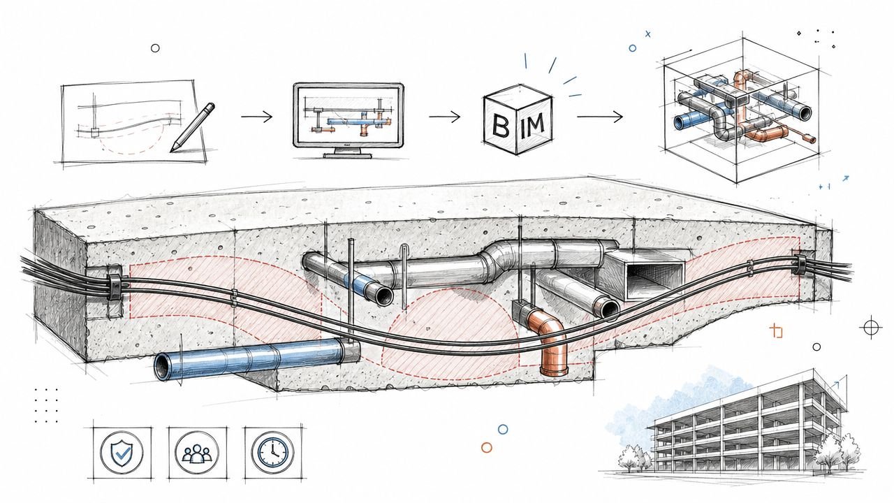
The BIM Coordination Workflow for CLT Openings
A CLT opening workflow succeeds or fails before the panel file goes to the fabricator. If duct sleeves, riser holes, access cutouts, and connection recesses are still moving during trade coordination, the model is only documenting risk.
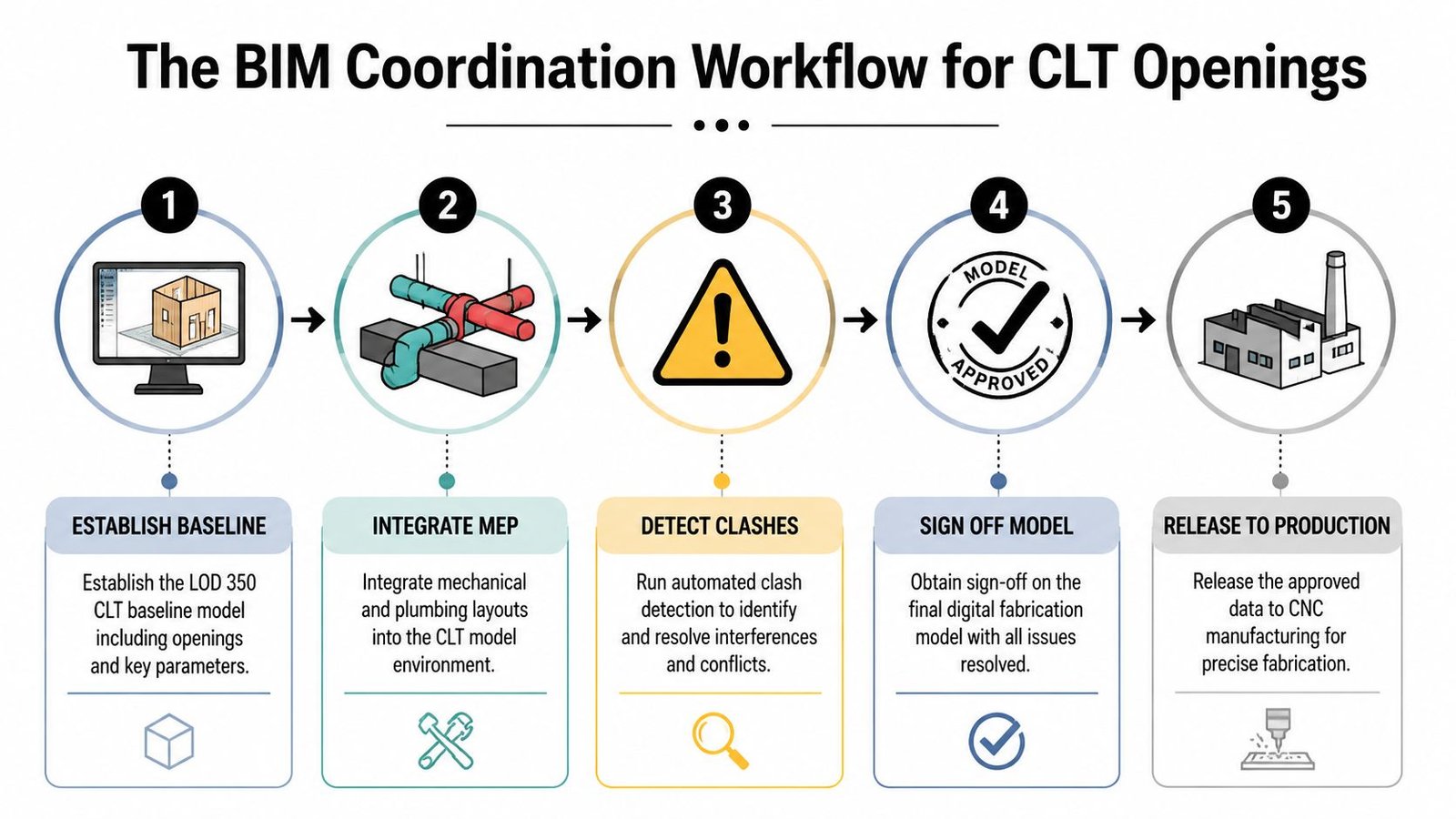
Start with a fabrication-ready panel model
The coordination model has to match how the panel will be manufactured, tagged, reviewed, and released. That means each panel needs stable boundaries, panel IDs, joint lines, bearing conditions, and any recesses or reserved zones that affect routing. Openings already cleared by architecture and structure need to be in place before MEP starts using the model for layout.
For coordination, the panel model should show:
- Accurate panel boundaries and IDs
- Joint locations
- Connection recesses or reserved zones
- Openings already approved by architecture and structure
- A consistent coordinate origin per panel
Trade routing may look clean in a federated model and still fail once the actual panel geometry, edge offsets, or connector zones show up.
Build the restrictions into the model
CLT coordination works best when the model makes prohibited routing hard to produce. Structural limits cannot stay in calculations, PDF markups, or meeting notes. They need to be modeled as testable conditions in Revit, Navisworks, or the coordination platform the team is using.
A workable builder-side process usually follows this order:
- Publish the CLT panel model as the host reference for all linked trade models.
- Add no-penetration volumes at panel edges, bearing areas, spline zones, and sensitive connection locations.
- Require MEP trades to route against those modeled restrictions, not against background sheets.
- Track every proposed penetration in a master opening log tied to panel ID and panel coordinates.
- Review and approve penetrations by panel release package, then issue that approved data into shop drawings and fabrication exports.
That sequence aligns with other off-site construction coordination workflows, but CLT leaves far less room for unresolved penetrations at release.
The penetration schedule controls the handoff
The model helps teams coordinate. The penetration schedule controls what gets cut.
A useful schedule records:
- Panel ID
- Opening location by panel coordinates
- Size and shape
- Trade ownership
- Sleeve or blockout requirement
- Fire or approval notes
- Structural review status
On well-run projects, the opening log is not an afterthought built at the end of coordination. It is the control document used during coordination. If a penetration exists in the model but not in the log, it is not approved. If it appears in the log without a model element, the team cannot verify clearance, sleeve requirements, or exact location.
Coordination checkpoint: If a penetration cannot be traced from model element to panel ID to approval status, it is not ready for fabrication.
Software matters less than discipline. Revit for authoring, Navisworks for clash detection, and a clean issue log are usually enough if one party owns the panel opening register and closes every approval loop. Some teams bring in outside production support for that control layer. BIM Heroes provides BIM coordination and construction document production services when the project team needs dedicated management of federated models and drawing output.
What Early Planning Looks Like on a CLT Project Schedule
“Plan early” is too vague to help a superintendent or precon manager. The schedule needs named checkpoints, and those checkpoints need to sit earlier than many teams expect.
The design freeze has to mean something
On a CLT project, a design freeze is not symbolic. It has to lock every decision that changes panel geometry or openings.
That usually includes:
- Window and door sizes
- Shaft dimensions
- Major MEP riser locations
- Equipment-driven duct and pipe pathways
- Connection-driven recesses that affect nearby services
If teams keep “minor” flexibility after that point, the freeze isn't real. It's just a meeting note.
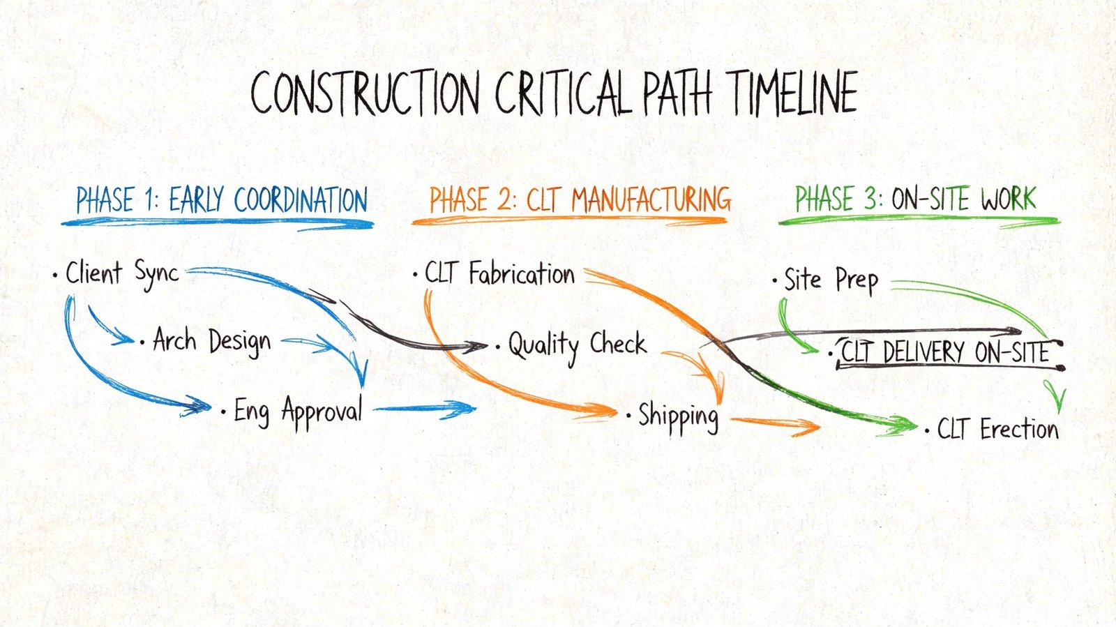
Work backward from fabrication, not permit
The better schedule logic starts at panel release and works backward. Fabricators cut from approved information, so every upstream task should be measured against that date, not just permit submission.
A practical preconstruction sequence often looks like this:
| Project checkpoint | What must be true |
|---|---|
| Architectural opening freeze | Geometry affecting panel cuts is locked |
| MEP routing milestone | Major routes and penetrations are placed in the federated model |
| Coordination review window | Clashes, edge conflicts, and sleeve requirements are resolved |
| Shop drawing review | Engineer and architect review panel drawings with openings shown |
| Fabrication release | Approved data goes to CNC cutting |
The front-loaded effort is the whole point
At this juncture, many first-time teams resist the process. They want CLT speed on site without accepting CLT discipline in preconstruction.
That trade does not hold. If routing starts too late, the project pushes uncertainty directly into fabrication. If the team front-loads coordination, erection becomes far more predictable because the work has already been decided digitally.
On CLT jobs, schedule certainty is purchased in preconstruction.
This is also why related coordination habits matter. Teams that already use disciplined issue tracking and model review usually perform better on mass timber projects. The same habits that prevent problems in MEP coordination clash detection or avoid common HVAC design mistakes carry over well here, but the tolerance for unresolved openings is tighter.
Reinforcement and Approval for Non-Standard Penetrations
The expensive mistakes show up after the model handoff, not during the meeting. A duct shifts 150 mm to clear another service, the revised opening lands near a support zone, and the team assumes the field can sort it out. On a CLT job, that assumption usually turns into a fabrication hold, an engineer RFI, or a panel revision that burns both float and money.
Some penetrations are routine. Others change how the panel works and how adjacent trades install around it. Panel thickness, support location, connection hardware, acoustic requirements, and enclosure detailing all affect whether an opening is acceptable as drawn. Treating every penetration like a simple core hole is how teams end up approving geometry that cannot be released.
Openings need engineer review when they create real section loss or conflict with how the panel carries load. That usually includes conditions such as:
- Large penetrations relative to panel depth or width
- Openings near edges, bearings, or connection zones
- Multiple penetrations grouped in the same area
- Cuts near concentrated loads or embedded hardware
- Repeated service openings that reduce the same strip of panel across several bays
Those are production decisions. They need to be checked against the actual panel layout, not marked up in isolation.
When an opening falls outside the standard rules, the team has four practical options. Reroute the service if the clash is found early enough. Add engineered reinforcement, often with a fastening pattern or local strengthening detail. Revise the sleeve strategy if the assembly can carry part of the requirement. Rework the panel layout or support logic if the opening is exposing a bigger coordination problem.
The order matters. Start with rerouting before asking the fabricator to cut more wood out of the panel.
Approval also has to close before release. The builder should issue a penetration schedule with location, size, elevation, edge distances, and nearby hardware or supports clearly shown. The structural engineer can then approve, require reinforcement, or reject the opening with enough context to make the call once. If that review happens after shop drawings are issued, the project is already late.
That is the discipline CLT demands. Opening geometry is part of manufacturing, not a late coordination clean-up item.
If your team needs help setting up CLT panel opening coordination in BIM, BIM Heroes provides BIM coordination and construction document support for mass timber projects. Ask for a coordination checklist, a penetration schedule template, or a review of the model handoff before the shop drawing package is released.