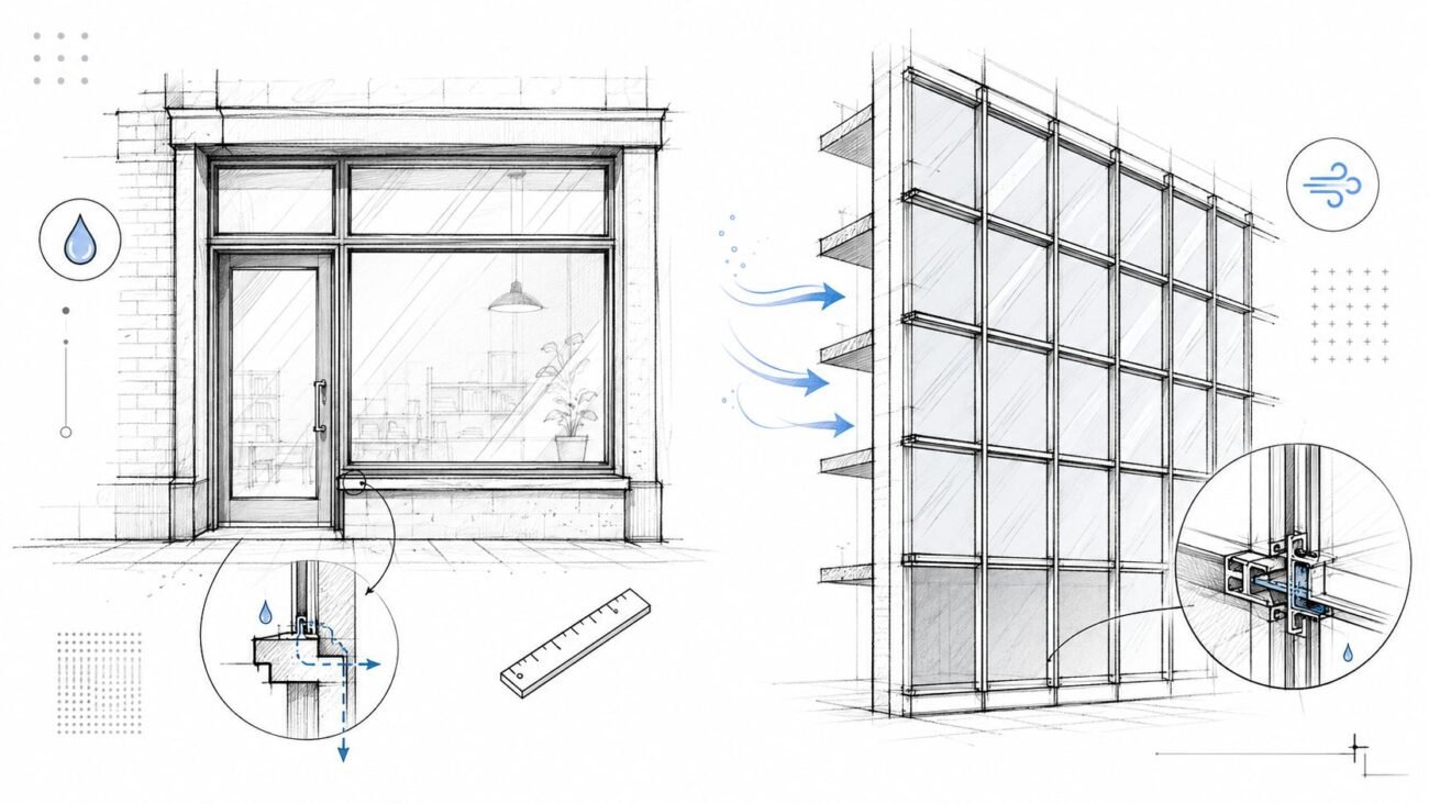
Modern envelopes create a mechanical design problem that older buildings could ignore. As infiltration drops, indoor air quality stops taking care of itself. The building may look excellent on the energy model and still perform poorly for occupants if outside air delivery is treated as a late coordination item instead of a core system requirement.
That's why a heat recovery ventilation system belongs in the same conversation as load calculations, shaft planning, controls, and permit notes. Heat recovery ventilation became mainstream as airtight standards expanded, and Natural Resources Canada notes that continuous ventilation systems were introduced as a requirement for airtight R-2000 homes before becoming common in new housing and major renovations. The same reference notes that ENERGY STAR qualified HRVs must meet a minimum sensible heat-recovery efficiency of 75% (Natural Resources Canada HRV guide).
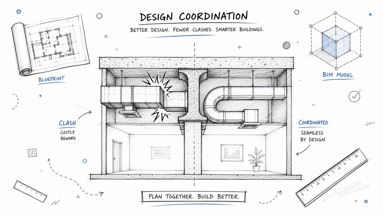
In practice, the hard part isn't deciding that recovery ventilation is useful. The hard part is integrating it without creating duct conflicts, weak control sequences, and commissioning failures that show up when the ceiling is already closed. A bad layout can erase the value of a good unit. A vague sequence of operations can turn balanced ventilation into intermittent ventilation. An uncoordinated exterior penetration can trigger RFIs that should never have existed.
The safest approach is to treat HRV and ERV design as a systems integration task from day one. Equipment choice, duct design, airflow paths, static pressure, access clearances, controls logic, and model coordination all need to line up early. That's what keeps the design buildable and keeps the field team from solving your omissions with change orders.
Introduction
The first coordination failure usually shows up before procurement. A high-performance envelope is locked in, ceiling space is already tight, and the ventilation concept still exists as a generic note instead of a routed, controlled, commissionable system. That is where margin starts to leak out of the job. RFIs follow. Exterior louver locations move. Controls points get added late. The field team ends up solving design gaps with time and change orders.
A heat recovery ventilation system only delivers its intended value when it is designed as part of the building system, not inserted after the main HVAC layout is already fixed. For engineers, the scope is broader than selecting a unit with acceptable catalog performance. It includes choosing the right system configuration, proving the unit can hold airflow at installed pressure, reserving maintenance access, coordinating penetrations, and making sure the controls sequence works with the primary airside strategy.
BC Housing gives a practical equipment selection reminder in Builder Insight 14 on heat recovery ventilation. Capacity should be selected with headroom above the continuous requirement so the system can still deliver boost airflow after real duct losses, fittings, balancing devices, and filters are accounted for. That is a design issue, not a sales submittal issue.
One line on a schedule is not enough.
On production work, the mistakes are predictable. The designer picks a nominal airflow point and never checks the fan curve against the installed static. The architect shifts the facade module and the intake and exhaust separation no longer works. The controls contractor receives a vague sequence and treats the HRV as a stand-alone fan box. Then TAB reports airflow shortfalls after ceilings are closed.
That is why this article treats recovery ventilation as a systems integration problem. The useful question is not whether HRV belongs on the project. The useful question is which of the four common HRV or ERV configurations fits the building, the shaft strategy, the controls architecture, and the BIM model without creating avoidable coordination debt. On projects pursuing tighter energy performance, that decision also needs to align with the broader code path, including ASHRAE 90.1 energy recovery requirements and exceptions.
The teams that get this right early usually protect both schedule and fee. The teams that treat it as a late add-on usually pay for the lesson in the field.
The Regulatory Driver for Heat Recovery Ventilation
The regulatory pressure behind heat recovery ventilation is stronger than many design teams admit early in DD. Once the project is aiming for a tighter envelope and formal outdoor air compliance, energy recovery stops being a nice feature and starts looking like baseline mechanical infrastructure.
ASHRAE 62.1 and 62.2 set the ventilation framework that pushes projects toward deliberate mechanical outdoor air delivery. In tight buildings, relying on leakage is no longer credible. That means the engineer has to show where outside air comes from, how it moves through the occupied space, and how the system performs when the main conditioning equipment isn't in the operating mode everyone assumed during schematic design.
Why code pressure keeps increasing
The market is moving in the same direction as the codes. Fact.MR projects the global heat recovery ventilator market will grow from USD 6.1 billion in 2025 to USD 8.9 billion by 2035, a 3.8% CAGR, driven by tighter energy regulation and indoor air quality demand (Fact.MR heat recovery ventilator market outlook). That doesn't prove any specific project needs an HRV, but it does confirm what most engineers already see in practice: more projects are requiring a serious ventilation integration strategy.
For commercial work, energy recovery requirements also interact with the energy code path. Teams working through 90.1 compliance need to understand how recovery ventilation affects system selection, economizer logic, and supporting documentation. If you need a broader refresher on that code environment, this ASHRAE 90.1 overview is a useful companion reference.
What permitting reviewers care about
Reviewers usually won't rescue a vague ventilation design. They'll ask for clearer sequences, termination locations, or system intent when the documents leave too much open. The recurring weak points are predictable:
- Outdoor air strategy: The set has to show how required ventilation is delivered, not just that a unit appears on the schedule.
- Energy recovery intent: If the design depends on recovery for compliance or performance, the drawings and notes need to make that visible.
- Operating modes: Occupied, unoccupied, economizer, and cold-weather behavior need enough control detail to be enforceable.
- Coordination evidence: Exterior penetrations, shafts, and service access can't be left to “contractor to coordinate” without inviting RFIs.
Good code response starts with good production discipline. If the ventilation path is real in the model and legible in the set, permitting gets easier.
HRV vs ERV Selecting the Right Equipment
The first decision is still the most consequential. Choose the wrong recovery device and every downstream choice gets harder, including controls, duct routing, frost management, and owner expectations about humidity.
HRVs and ERVs both recover energy from outgoing air. The difference is what gets transferred. An HRV handles sensible heat exchange. An ERV handles sensible and latent transfer, which means moisture comes into the design conversation.
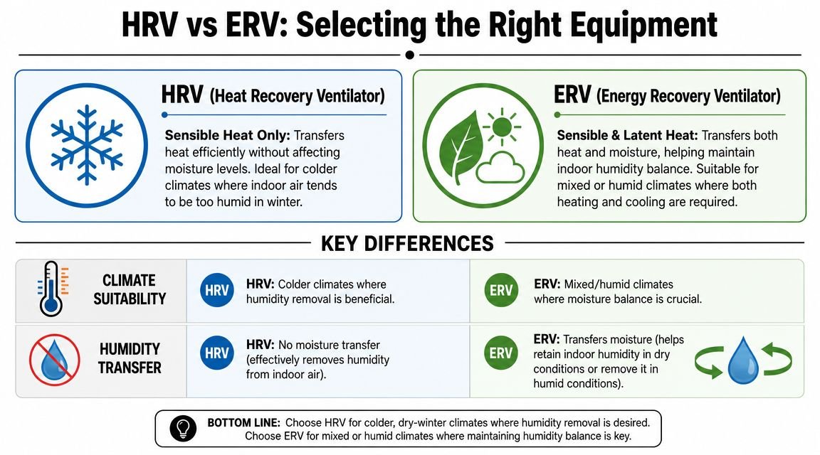
Climate should drive the default choice
If you're working in a cold climate, HRV is often the cleaner starting point. Manufacturers such as Carrier position HRVs as ideal for colder and northern conditions because they focus on sensible heat exchange. Technical summaries commonly place sensible recovery for plate and air-to-air systems in the 70% to 90% range, which is why they are effective at pre-warming intake air before distribution (heat recovery ventilation technical summary).
If the project is in a warm humid climate, ERV usually makes more sense because latent transfer matters. If the project sits in a mixed climate, occupancy and owner priorities often break the tie. You're not just choosing efficiency. You're choosing how the building handles moisture.
Occupancy matters more than designers think
Climate alone doesn't finish the job. Some occupancies make the answer obvious:
| Occupancy condition | Better starting point | Why |
|---|---|---|
| Cold-climate residential or small office | HRV | Sensible recovery is the main need |
| Humid mixed-use or warm commercial | ERV | Moisture transfer supports better OA conditioning |
| Pool, locker, or high-humidity exhaust condition | HRV | You usually don't want exhaust moisture transferred back into supply |
| Airtight retrofit with limited duct paths | Depends on system layout | Coordination constraints may outweigh idealized selection |
Junior designers often get tripped up when they pick by climate map, then ignore the exhaust profile. Kitchens, wet areas, and specialty spaces can change the correct answer quickly.
The right recovery device is the one that fits the building's moisture behavior, not the one with the nicest catalog language.
Don't read ratings without reading conditions
When reviewing equipment data, look beyond the top-line efficiency claim. The field result depends on airflow, static pressure, frost strategy, and how the unit is connected to the rest of the system. Higher core efficiency can mean higher pressure drop. That tradeoff is real. If the fan can't overcome the installed duct resistance, delivered performance suffers.
That's why the selection step should include these checks:
- Installed airflow check: Confirm the target airflow at the project's actual pressure conditions, not free-air assumptions.
- Frost strategy review: In colder work, identify whether the unit needs bypass, preheat, or another defined protection method.
- Exhaust profile review: Check whether the building's moisture and odor sources make latent transfer helpful or counterproductive.
- Distribution intent: Decide early whether the supply air will be delivered directly, mixed with return, or tied into a DOAS strategy.
Four Core HRV and ERV System Configurations
The configuration decision has more impact on actual performance than many equipment comparisons. A strong unit in the wrong layout will underperform a simpler unit that's integrated cleanly. The four common arrangements below cover most project conditions.
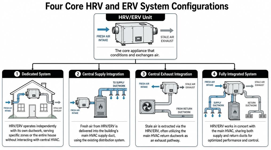
Dedicated standalone ducted system
This is the cleanest ventilation logic. The HRV or ERV has its own supply and exhaust duct network. It doesn't depend on central heating or cooling fan runtime to move ventilation air.
That independence is the main advantage. In residential and light commercial work, it gives the designer better control over continuous ventilation. It also avoids the problem of trying to make a low-static ventilation unit behave like part of a higher-static central air system.
The downside is coordination burden. You've added another duct system to an already crowded building. That affects framing, ceiling depth, exterior penetrations, and balancing.
Best fit is usually airtight residential new construction, major renovation, and smaller buildings where ventilation continuity matters more than first-cost simplicity.
Return-side integration with central HVAC
This arrangement sends recovered outdoor air into the central return plenum so the air handler can finish conditioning and distribute it. It can reduce diffuser-level comfort complaints because the supply air reaches occupied spaces through the main HVAC system.
But it comes with a tradeoff. Ventilation becomes linked to central system operation unless the control sequence is very deliberate. It can also reduce recovery effectiveness because the unit isn't necessarily seeing the strongest possible temperature differential in the most direct way.
This approach works best when the central system runs consistently during occupied periods and the design team accepts that integration convenience may come at a performance penalty.
DOAS-based integration
For many commercial projects, this is the most disciplined answer. The recovery device is part of a dedicated outdoor air system, while terminal systems handle space conditioning. Ventilation and load control are separated instead of forced through one compromise path.
That usually gives the engineer cleaner control logic, better outdoor air accountability, and stronger coordination with energy compliance strategy. It also creates one of the most congested coordination scenarios in the model because the DOAS ducts, exhaust paths, piping, structure, and access clearances all compete in the same spaces.
Use this configuration when ventilation is a first-order design problem, not a secondary add-on.
Economizer bypass integration
On projects with economizer operation, recovery ventilation has to be coordinated with bypass logic. Otherwise, the recovery core can work against the free-cooling intent.
The key is not the presence of an economizer alone. It's whether the recovery system is configured to stop helping when “help” becomes counterproductive. That requires actual controls coordination, not just separate notes from different manufacturers pasted into the spec.
A practical review checklist for this layout:
- Bypass path shown: The drawings should make bypass intent visible, not leave it buried in controls notes.
- Sequence alignment: Economizer and recovery logic should be written as one operating sequence.
- Sensor responsibility: The set should make clear which system is the controlling authority in each mode.
- Access and service: Bypass dampers and actuators need maintainable locations, not leftover voids above inaccessible ceilings.
Duct Design Fundamentals for HRV Systems
A common site problem goes like this. The unit is installed, startup begins, and the balancing report shows the airflow is short even though the equipment schedule looked fine on paper. The root cause is usually in the ductwork. The fan was asked to overcome more resistance than the design allowed.
For small and medium HRV systems, there is very little slack in the fan curve. If the layout picks up extra elbows, long flex runs, tight ceiling offsets, or restrictive exterior hoods during coordination, delivered airflow drops fast. The practical lesson is simple. Size the duct system around the actual external static pressure the unit can carry, and leave margin for balancing, dirty filters, and the routing changes that happen between DD and shop drawings.
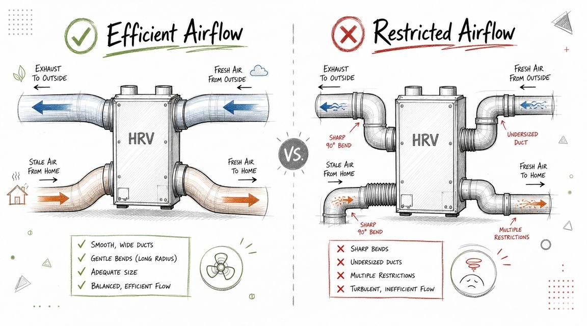
What good duct design looks like
Start with the fan table, not a standard branch detail from another project. HRV and ERV systems are less forgiving than many central air systems because the available static is limited and the airflow target is tied directly to code ventilation, not just comfort.
A workable layout usually has four characteristics:
- Supply and exhaust stay fully separated: Keep the airstreams distinct all the way through distribution and termination. Shared plenums, casual transfer paths, or ambiguous connections create contamination risk and field confusion.
- Exterior terminations are treated as part of the system: Intake and exhaust locations need real separation, weather protection, and envelope coordination early enough to avoid late façade revisions.
- Routing is modeled as it will be built: Tight offsets, fitting counts, access zones, and sleeve locations belong in the model. Abstract single-line intent is where coordination debt starts.
- Service space survives coordination: Filters, core pull, trap access, and damper actuator access need clear working room after ceilings, lights, cable tray, and structure are finalized.
System configuration matters. A simple point-to-point residential layout, a centralized corridor system, and a DOAS-coupled recovery unit do not tolerate the same duct strategies. The designer has to match fitting count, branch control, and shaft allocation to the configuration selected earlier, or the BIM model will show a clean route that the fan cannot support in operation.
Where coordination usually breaks down
Exterior penetrations generate a disproportionate number of RFIs because they affect architecture, structure, waterproofing, and commissioning all at once. If intake and exhaust penetrations stay provisional too long, the team ends up relocating them after permit, adding unexpected offsets, or accepting poor separation because the wall area is already committed.
Ceiling congestion is the second failure point. Recovery ventilation ducts often get treated like “small add-on” routing, then lose every clash decision to larger supply mains, piping, and structure. That approach protects nobody's fee. The added pressure drop shows up at TAB, then the contractor requests a change, the engineer reviews a field workaround, and the owner gets a system that only works in boost or never reaches design exhaust.
Develop the duct path with the same discipline used for hydronic mains and major supply trunks. On tight projects, HVAC duct layout drawing standards and workflows help the team lock routing intent early enough to protect airflow, access, and penetration locations before fabrication starts.
A low-static ventilation system has very little tolerance for field improvisation.
Controls Integration with Central HVAC
A recovery ventilation unit without a clear sequence of operations is just a mechanical placeholder. The equipment may run, but that doesn't mean the building gets the ventilation pattern the engineer intended.
The first issue is continuity. If the project depends on mechanical ventilation for occupied air quality, the sequence has to define when the unit runs, when it modulates, and how it behaves when the central HVAC system is in an alternate mode. Return-side integrations are especially vulnerable here because designers assume fan runtime that never occurs in operation.
Minimum ventilation logic
The ventilation system has to keep doing its job when the building shifts modes. Occupied periods, setback conditions, and transitions all matter. If outside air delivery disappears because the central fan is off and no interlock covers that condition, the system is functionally incomplete.
A strong sequence should identify:
- Run status logic: When the HRV or ERV operates independently and when it is enabled by central HVAC status.
- Minimum airflow floor: The lowest permitted operating point when the building is occupied.
- Mode transitions: What happens when occupancy, temperature control, or economizer logic changes state.
- Alarm behavior: Which failures generate BAS alarms and which are handled locally.
Frost and BAS considerations
Cold-climate projects need explicit frost control logic in the sequence. Don't leave that entirely to factory default settings unless the design intent accepts the manufacturer's unmanaged response. The project team should know whether frost protection is handled through bypass, preheat, or another method, and what that does to operating behavior.
For commercial work, BAS integration also matters. Owners need meaningful points, not a black-box accessory that only the installer can interpret. Fan status, supply and exhaust temperatures, fault conditions, and frost mode should all be visible if the system is expected to be maintained properly.
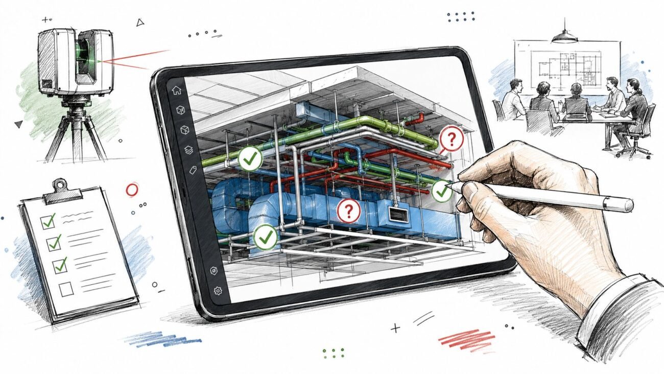
Commissioning and Performance Verification
The design either holds up or gets exposed. A recovery ventilation system that isn't balanced and verified can look complete on the drawings and still miss the owner's actual performance expectations.
Start with airflow balancing. Supply and exhaust need to be balanced closely enough to support the intended building pressure relationship. If one side drifts materially from the other, pressure problems show up fast in occupant comfort, envelope behavior, and odor migration.
What to verify before turnover
A disciplined commissioning pass should include:
- Airflow confirmation: Verify delivered supply and exhaust rates at installed conditions, not assumed settings.
- Functional sequence testing: Confirm the unit responds properly in normal operation, alternate modes, and fault conditions.
- Recovery performance check: Measure the relevant air temperatures and compare actual sensible recovery to the specified expectation.
- Duct integrity review: Where ducts run through vulnerable locations, leakage and insulation quality matter to system outcome.
If the TAB report and controls trend don't agree, trust neither until the field condition is checked.
The point of commissioning isn't paperwork. It's proving that the installed system still matches the design logic after routing compromises, balancing changes, and controls programming have all had their turn at it.
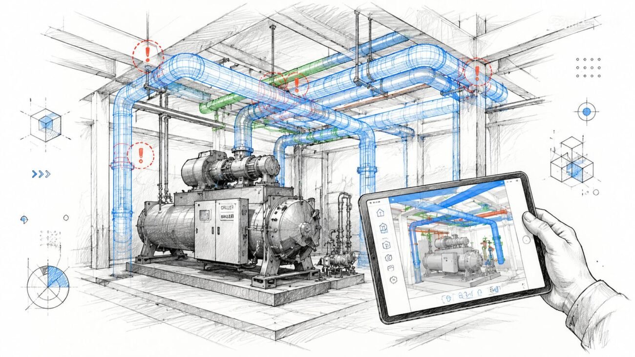
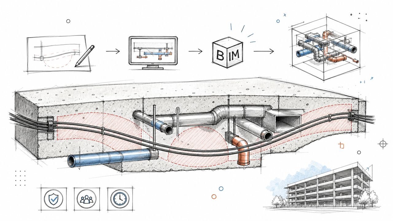
BIM Coordination for HRV Integration
Heat recovery ventilation adds coordination density fast. You're not just placing one more box. You're adding outdoor air, exhaust, terminations, access clearances, controls interfaces, and sometimes a parallel duct network in already crowded ceiling space.
AHRI-related guidance makes the practical risk clear: even high-efficiency HRV units with 70-95% sensible recovery can underperform when duct design, balancing, and coordination are poor (AHRI overview of air-to-air recovery ventilators).
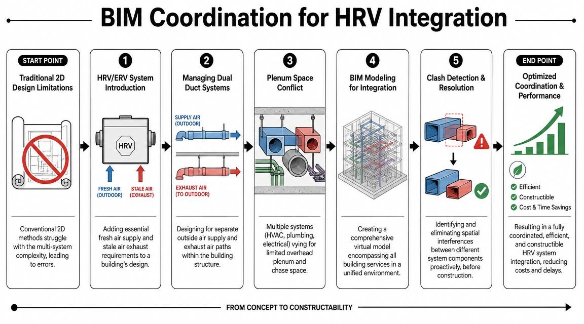
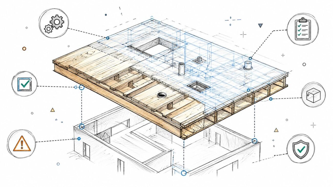
What needs to be in the model
A useful coordination model shows more than duct centerlines. It needs unit location, service clearance, intake and exhaust routing, penetration positions, and the relationship to structure and envelope. If the model leaves those elements abstract, clash detection won't protect you from field problems.
The priority conflicts are usually consistent:
- Plenum congestion: Recovery ducts competing with primary supply, return, plumbing, cable tray, and framing.
- Envelope conflicts: Intake and exhaust penetrations landing in bad façade zones or interfering with detailing.
- Access failures: Unit locations that technically fit but can't be serviced.
- Sequence disconnects: Mechanical layout that doesn't support how controls are supposed to work.
For firms standardizing delivery, Revit-based MEP coordination helps make those issues visible before permit and before procurement. Teams that need a model-based workflow reference can look at MEP coordination in Revit as one example of that process. BIM Heroes also provides MEP coordination and construction document production support where ventilation systems like these need to be modeled, coordinated, and documented as part of the full project set.
The broader lesson is simple. A heat recovery ventilation system is easy to specify and easy to underestimate. The projects that go smoothly are the ones where the team models accurate airflow paths, resolves the penetrations early, writes the controls clearly, and leaves enough room for maintenance.
If you're working through HRV or ERV integration on a live project and need support with MEP coordination, duct routing, or permit-ready construction documents, BIM Heroes can help. The best time to solve these issues is before RFIs start. If a checklist, template, or model review would help your team tighten the workflow, it's worth starting that conversation early.