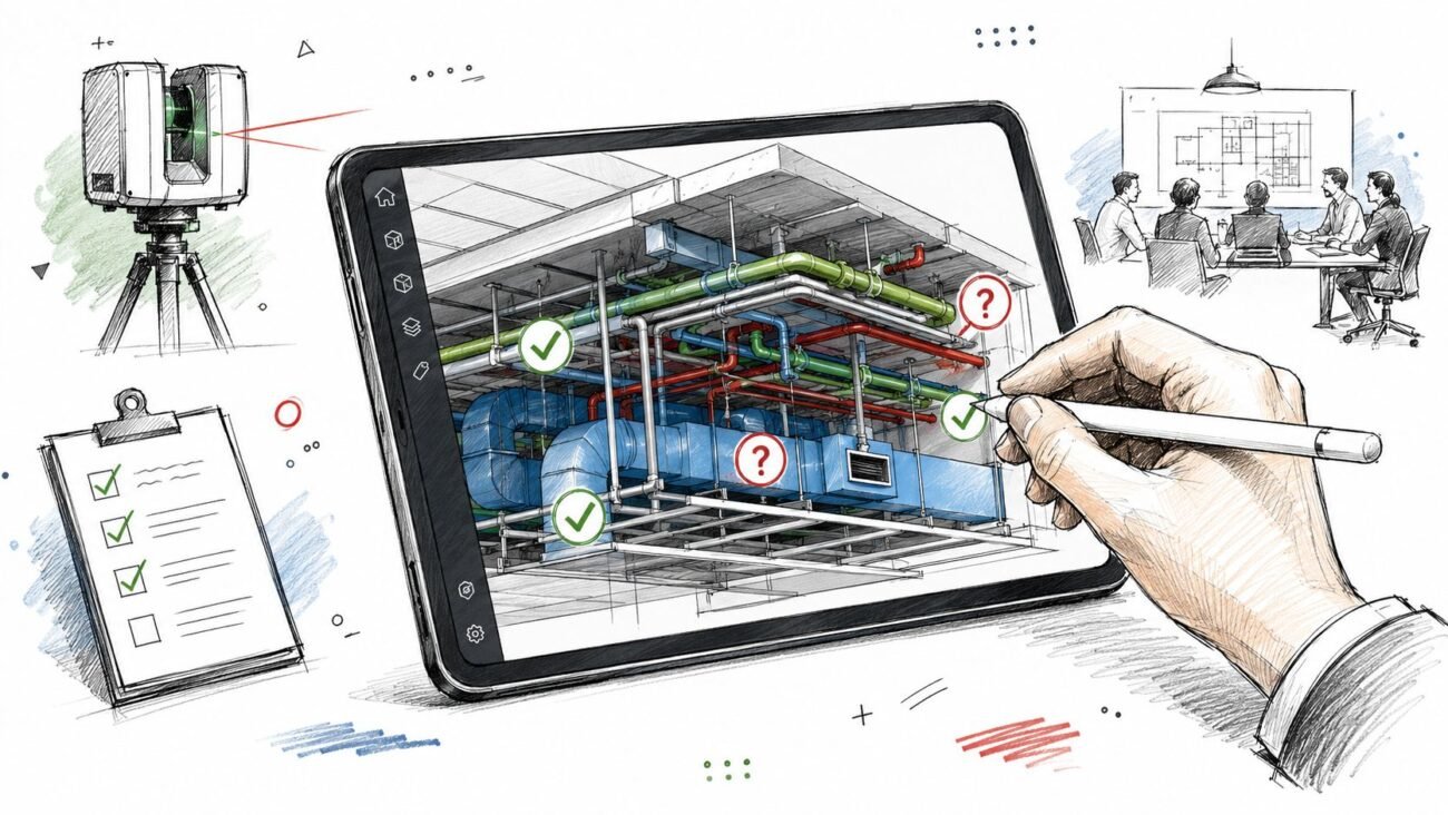
The chilled water mains were installed through the mechanical room, then the piping crew hit the wall opening and stopped. The sleeves had been sized from design drawings that showed bare pipe, not insulated pipe, so the actual assembly wouldn't fit through the cast opening. Now the wall has to be cored, the structural engineer has to sign off, and mechanical rough-in is delayed by three weeks.
That kind of miss doesn't happen because teams don't understand a chilled water HVAC system. It happens because the model was treated like a picture instead of a production tool. On chilled water work, that mistake gets expensive fast. Pipes are bigger, equipment is heavier, penetrations are less forgiving, and every bad assumption compounds downstream into RFIs, field fixes, and schedule drag.
On data-heavy facilities, the coordination stakes go even higher, which is why this guide to data center cooling design is a useful companion read for teams dealing with dense mechanical rooms and tight service envelopes. The same coordination discipline applies even when the load profile changes.
The practical standard is simple. Before construction starts, the HVAC chilled water model construction package has to show the actual installed condition, not a design abstraction. That means insulation, clearances, supports, access zones, penetrations, electrical pathways, and expansion provisions all need to be resolved before fabrication and rough-in. If the model can't support those decisions, it isn't ready.
Introduction
Most chilled water coordination failures start with one of two shortcuts. Someone models bare pipe because it's faster, or someone places equipment families by footprint and leaves access to “field verify later.” Both are predictable. Both wreck margin.
A chilled water HVAC system is usually serving medium and large-size buildings and other facilities with substantial cooling demand, where centralized cooling architecture makes sense for scale and maintenance access, as noted in this overview of chilled-water systems in large buildings. That scale changes the coordination standard. You're not just routing services. You're locking in structural openings, electrical feeders, maintenance access, and the sequence of multiple trades.
The production mindset has to shift early. A mechanical room model should answer hard questions before submittals are approved and before concrete is poured. Can the chiller get into the room? Can the tube bundle be removed later? Are both supply and return mains routed with insulation and support space? Do the standby connections exist in the same overhead zone as the active system?
Bare pipe in a coordination model is a false positive factory. It tells the team everything fits right up until the field proves otherwise.
The rest of the work is about gates. Not theory. Not generic BIM “best practices.” Real checkpoints that keep the chilled water system BIM coordination package buildable, maintainable, and permit-ready.
Why Chilled Water Systems Require Earlier BIM Coordination
A chilled water HVAC system takes up space in ways smaller distributed systems don't. The issue isn't just pipe diameter. It's the total installed envelope, the weight on structure, and the fact that these systems rarely travel alone. They move with pumps, valves, strainers, controls, electrical infrastructure, and usually some form of redundancy.
Pipe size changes the whole overhead plan
In commercial work, chilled water mains often land in the 4 to 12 inch range before insulation. Once insulation is added, the outside dimension can become 6 to 16 inches in practice. That's where corridor coordination starts to fail. A line that looked manageable in plan now competes directly with branch ducts, cable tray, conduit banks, and beam penetrations.
Water can carry large cooling loads efficiently because its heat-transfer film coefficient can be 10 to 100 times better than air, which is one reason chilled-water systems work so well across long runs in large facilities, according to this technical explanation of chilled-water air conditioning systems. The coordination consequence is obvious. The hydronic system becomes physically dominant.
If you're building a coordination workflow around this system type, the safest starting point is a dedicated MEP coordination process that treats insulated pipe dimensions as the base condition, not a later add-on.
Equipment is large, heavy, and intolerant of bad assumptions
A chiller that fits the room on paper can still fail procurement if no one checked the delivery path, rigging route, housekeeping pad elevation, or final service clearances. Renovation work makes this worse because existing door widths, slab depressions, and shaft access rarely line up with current equipment selections.
Then there's redundancy. If the system has primary and standby loops, or duty and standby pumps, the model has to carry both simultaneously. Teams sometimes coordinate only the active path because it's cleaner visually. That shortcut hides the actual space claim and pushes the conflict to installation.
Earlier coordination protects fabrication, not just design intent
Chilled water piping Revit MEP content can't be schematic once the job moves into coordination. Every trade downstream needs the installed dimensions. The model has to support spool decisions, opening schedules, and room-by-room overhead zoning. If the team waits until shop drawing stage to model the full condition, the field is already exposed.
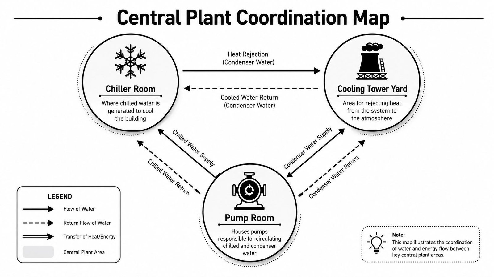
Central Plant Equipment Coordination
The central plant is where the job either gets disciplined or starts drifting. If the chiller room, cooling tower area, and pump room aren't modeled as operational spaces, every downstream layout becomes guesswork.
Model the service envelope, not just the equipment body
A chiller family without tube-pull clearance is incomplete. Same for pumps without motor access, towers without basin service space, or electrical panels without working clearance. The equipment may “fit” in Navisworks and still be unserviceable the day the owner needs maintenance.
A U.S. federal design specification shows the scale gap clearly. Water-cooled chillers can reach capacities up to 1,250 tons, while air-cooled chillers are typically capped around 200 tons, which is a useful reminder that central plant coordination deals with large, high-impact equipment from the outset, per this federal mechanical design specification.
That scale also makes reliability planning part of coordination, not a separate maintenance conversation. Teams that want a useful operations-side perspective should review these strategies for chiller reliability, especially when layout decisions affect serviceability and lifecycle access.
What needs to be locked before procurement
A central plant model should answer these questions before equipment is bought:
- Chiller access: Can the unit enter the building, turn into the room, and sit on the correct base without field demolition?
- Tube pull zone: Is there a protected service zone that remains clear of pipe, conduit, and structural obstructions?
- Pump skid geometry: Are suction and discharge connection locations based on submittal data instead of placeholder families?
- Cooling tower support: Has the structure been reviewed for the actual operating configuration, not a preliminary concept layout?
A mechanical room that only works during design review doesn't work. It has to work on delivery day, startup day, and ten years later when someone has to pull a bundle or replace a pump motor.
Cooling tower coordination usually fails at the interfaces
The tower itself is only part of the problem. Clashes often happen at the interface points. Connection pipe sizes, screen walls, access ladders, basins, and roof framing all want the same space. If the model doesn't include those dependencies, the plant coordination is incomplete even if the tower footprint is correct.
Piping Coordination in the Model
Most chilled water coordination failures come from piping that was modeled too optimistically. The pipe route looked clean because the model left out the things the installer has to build around.
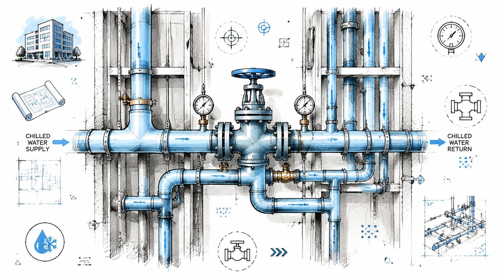
Insulated dimensions are the real dimensions
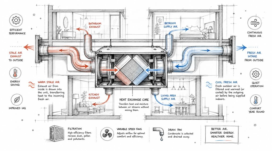
A chilled water HVAC system is typically designed around 43 to 47 °F (6 to 8 °C) supply water, and that operating range is one reason effective insulation is necessary to control condensation and energy loss, as reflected in this institutional chilled-water design standard. In coordination terms, that means the model must show insulated outside diameter. Anything else is fiction.
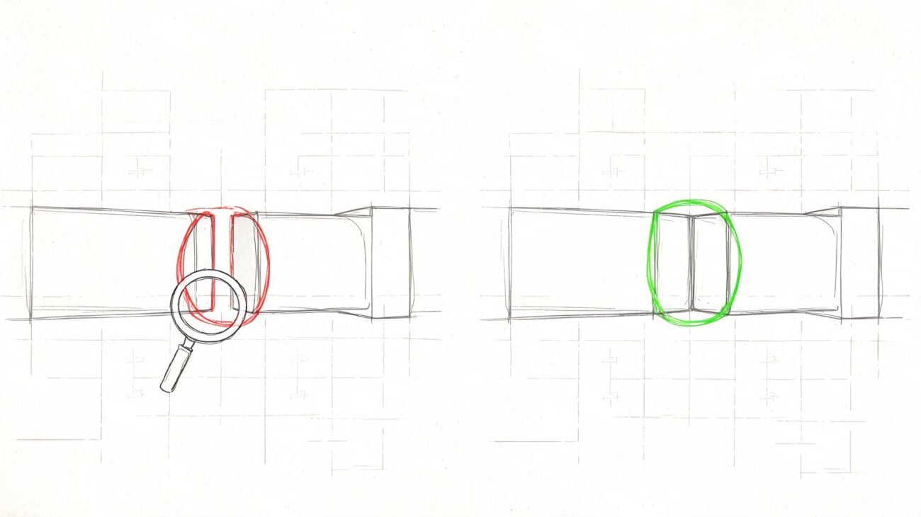
On real jobs, insulation thickness changes pipe behavior in the model more than people expect. A route that clears a duct by a small margin on bare pipe can become a direct clash once insulation and hanger space are added. Running clash detection before those dimensions are in place only creates rework.
Supply and return have to be coordinated together
Chilled water systems carry supply and return mains in parallel. That sounds obvious, but teams still coordinate one line first and “find room” for the second later. In corridors and interstitial zones, that shortcut breaks ceiling strategy quickly.
The production rule is simple:
- Model both mains together: Never reserve space for supply and assume return can follow.
- Set the vertical strategy early: The separation between mains affects branch takeoffs, valve access, and crossing logic with other services.
- Carry valves and specialties in place: Balancing valves, strainers, and sensors change the envelope and service access.
For teams preparing downstream fabrication or installation packages, clean isometric drawings for plumbing and MEP systems become much more reliable when the coordination model already includes the true insulated geometry.
Hangers are part of the coordination problem
Pipe supports get ignored because they're repetitive. That's exactly why they create field pain. Chilled water mains are heavy, and trapeze hanger locations need to land where structure can receive them. If a hanger hits open web steel in the wrong place, or misses the concrete insert zone, the installer starts improvising. Improvised support means delay, extra steel, and often a structural question that should have been closed weeks earlier.
A practical QA pass should check supports against framing before the route is considered released.
Thermal Expansion Coordination
Chilled water pipe moves. The model has to show where that movement is absorbed and what space is being protected for it. If it doesn't, another trade will eventually occupy that space.
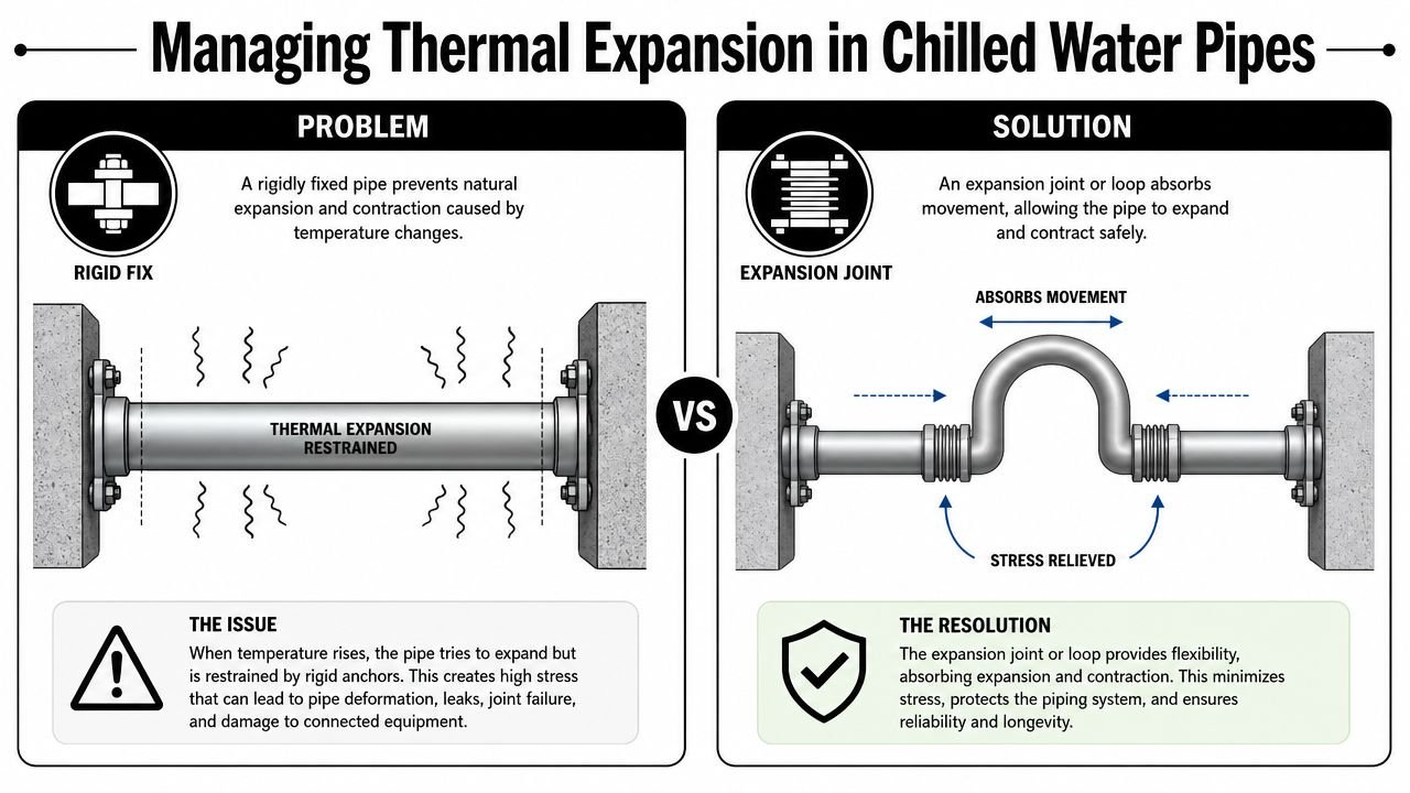
Expansion loops need reserved geometry
Expansion loops and offsets are often treated as engineering details that don't matter until later. In coordination, they matter early because they consume overhead width that other trades also want. If a loop needs lateral clearance, that clear zone has to be held in the model like any other no-go envelope.
What usually goes wrong is timing. The straight run gets coordinated first because it's easy to route. The loop gets inserted later, after ductwork or cable tray already owns the side clearance. That's when the redesign starts.
The loop isn't a note. It's a space claim.
Expansion joints shift the problem to structure
Where overhead room is too tight for loops, teams use expansion joints. That can solve one layout issue and create another. Joints need guides and anchors, and those supports have to line up with the structural system. If the anchor point lands where no suitable framing exists, the field fix usually means added steel and a new round of approvals.
A better workflow is to identify expansion locations during coordination and push those anchor requirements into the structural review before framing is finalized. The model should show the supporting logic, not just the pipe centerline. Hanger patterns also change around these points, so support families or detailing placeholders need to reflect the altered conditions near loops and joints.
Coordination with Electrical and Structural
The expensive coordination failures on chilled water jobs usually show up after the mechanical model looks "done." A chiller gets a clean pipe layout, then electrical tries to bring in feeder conduits or bus duct and finds the approach blocked by steel, duct mains, or access clearance. At that point, the model has already given the team false confidence.
Electrical paths have to be modeled as release items
Major equipment power is not a field-routing exercise. Chillers, pumps, and associated starters need real pathways from the distribution equipment to the final connection point, with bend space, access, and installation sequence considered in the same model.
Mechanical and electrical have to lock a few items early. Equipment orientation affects where feeders can enter. Housekeeping pad height and isolator selection change stub-up elevations. Disconnect locations affect working clearance and can turn a workable plant room into a code conflict if they get placed late.
I treat electrical routing to chillers as a production gate, not a follow-up task. If the feeder path is not coordinated in the federated model, the equipment is not ready for release.
Structural needs the installed load path, not a placeholder
Structure cannot review chilled water equipment from catalog assumptions alone. The structural team needs the condition that will be built and operated, including support logic that reflects the final arrangement in the room and on the roof.
The coordination set should show:
- Operating weight: Review should be based on filled and operating conditions, not shipping weight.
- Isolator height: Springs and inertia bases change final elevations and connection geometry.
- Support layout: Chiller bases, pump skids, pipe supports, and tower support points drive framing reactions and housekeeping details.
One miss shows up over and over. Mechanical issues a model with generic equipment families, structural sizes framing around it, then the approved submittal adds different base dimensions, higher isolators, or shifted support points. If steel or embeds are already released, the correction is no longer a model edit. It becomes added steel, revised anchors, new approvals, and lost labor in the field.
Good coordination practice is simple. Freeze the equipment support assumptions before structure issues for fabrication, and make sure the model carries enough information for hanger, base, curb, and feeder decisions to be checked by the right trades. That is how chilled water coordination protects margin instead of creating rework.
What Must Be Resolved Before Construction
Before construction starts, the chilled water system BIM coordination package needs formal go or no-go gates. If a team can't answer these checks cleanly, the system isn't ready for field release.
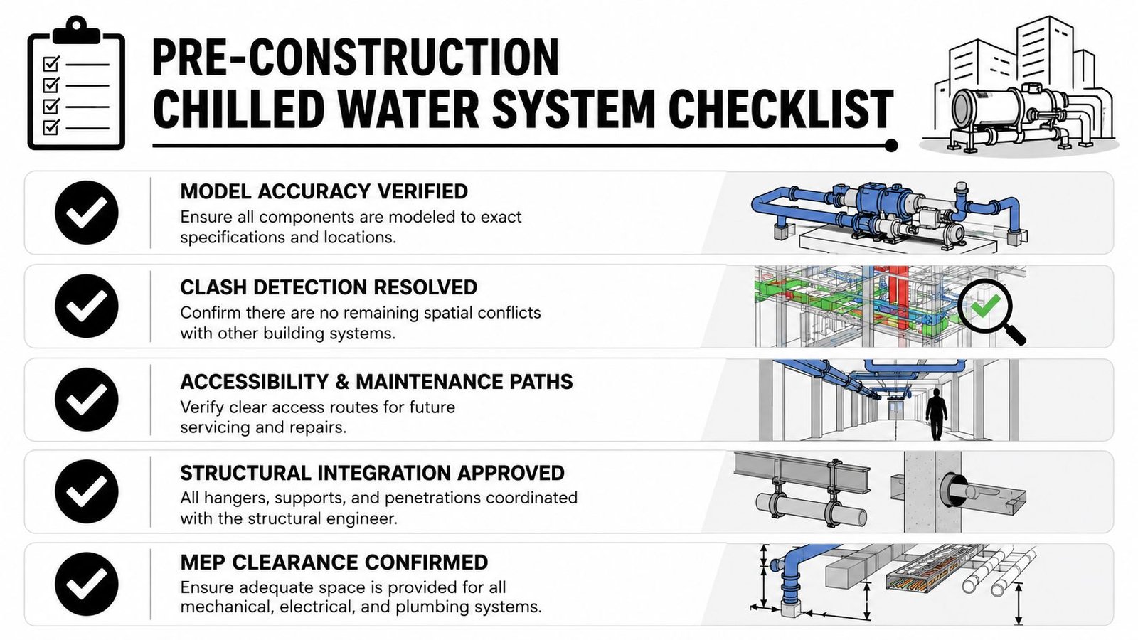
The five gates that protect schedule and margin
-
Insulated pipe verification is closed
Every chilled water line in the model must reflect installed outside diameter. Clash detection should run only after that condition is confirmed. -
Mechanical room clearances are signed off
Chiller, pump, and tower service zones need to match approved submittals, not design placeholders. -
Penetration schedules are issued from the coordinated model
Structural openings should be extracted from the latest model with insulated dimensions included. Failure to do so often leads to a lot of avoidable wall and slab rework. -
Expansion provisions are physically coordinated
Loops, offsets, or joints need protected space, support logic, and structural interface review before routing is frozen. -
Electrical routing to major equipment is coordinated
The path from switchboard to chiller has to be clash-free in the same model environment as the mechanical release set.
Controls and valve details are part of readiness
Variable-flow systems need the right valve strategy to deliver the intended result. Engineering guidance on chilled-water distribution notes that two-way valves must be correctly sized and controlled, and poor valve selection can prevent variable-flow systems from delivering expected savings, based on this chilled-water distribution guidance.
That's not just a controls discussion. It's a model QA issue. Valve type, orientation, access, and control intent affect spool lengths, service clearances, and field installation logic. Teams that want better coordination turnover usually benefit from reviewing broader MEP systems modeling workflows before they lock fabrication packages.
If a coordination model can't generate reliable openings, access checks, and install sequences, it isn't a construction model yet.
Common BIM Coordination Failures on Chilled Water Projects
I've seen chilled water rooms called “fully coordinated” a week before release, then watched the field reopen walls, shift supports, and redraw spool pieces because the model only represented design intent. The repeat failures are rarely caused by Revit or clash software. They come from weak production gates, loose family standards, and teams approving models that do not reflect the installed condition.
The failures are predictable.
-
Bare pipe was used for clash detection
The model cleared. The insulated system did not, so hangers, wall openings, and adjacent trade routes all ended up wrong. -
Chiller tube-pull clearance never made it into the family
The equipment fit on plan, but the room could not support maintenance without demolition risk or access changes. -
Expansion loop space was never protected in the overhead zone
Once another trade occupied that space, the chilled water route lost the movement allowance it needed. -
Structural penetrations were taken from design drawings instead of the coordinated model
Openings got based on pipe core diameter, not the actual insulated assembly and support condition. -
Pump skid geometry stayed at design-development level
Submittal dimensions and connection locations shifted late, after piping had already been coordinated around old assumptions. -
Cooling tower loading reached structural too late or in incomplete form
Operating weight, support points, and access implications should be issued early enough to affect steel, not after it is fixed.
Good teams catch these items before a model is issued for construction. They treat coordination like shop production. Every release has to pass QA checks for install geometry, access, openings, supports, and sequence.
That discipline protects margin. Field crews install what the model approves, whether the model is right or not.
If your team needs tighter chilled water coordination, permit-ready model QA, or central plant clash resolution, BIM Heroes can help. If you are not ready for that conversation, build a release checklist first. Check insulated dimensions, service clearances, opening sizes, expansion space, and major electrical routes before any package leaves coordination. Those checks stop a large share of the rework that burns schedule and fee.