Meta description: Construction of data center projects fails in the field when BIM coordination starts too late. Learn what the model must show before construction, from power and cooling to cable tray, fire suppression, penetrations, and raised floor coordination.
Category: BIM Technology & Workflows
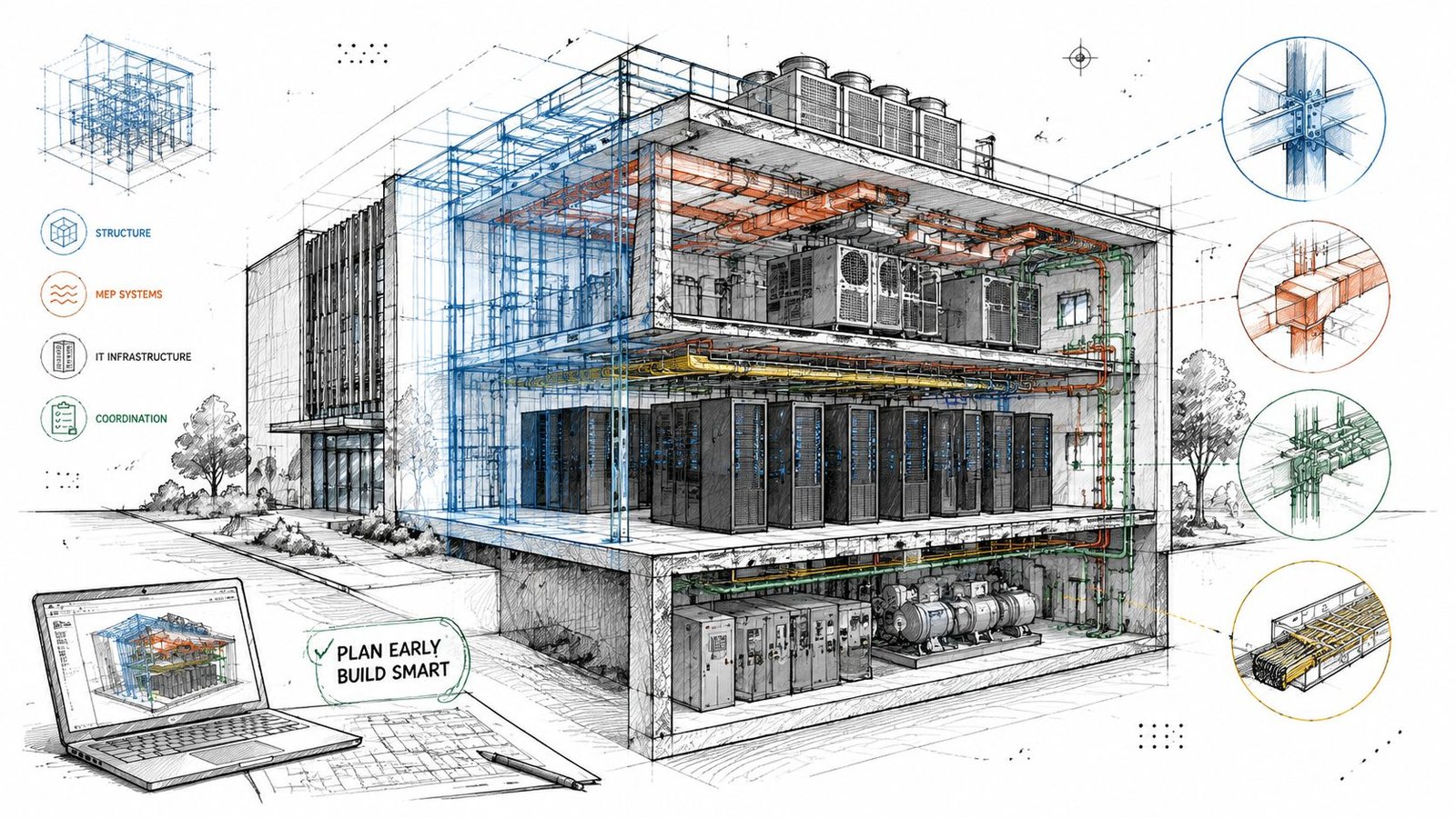
Structural steel was going up, but the MEP coordination model still wasn't finished. The raised floor height was still moving. CRAC locations were still being adjusted. Overhead cable tray routing was still schematic. By the time the coordinated model caught up, the project team found conflicts at penetrations that had already been formed, poured, and closed.
That's how rework starts on the construction of data center facilities. Not with one dramatic mistake, but with a sequence problem. Field activity moves ahead while the model is still acting like a design placeholder instead of a production control tool.
Data centers don't absorb that kind of drift well. The equipment density is too high. Redundancy systems compete for the same volume. Power, cooling, cable management, fire suppression, and structure all depend on a narrow set of coordination decisions being fixed early. If those decisions stay loose, the field pays for it.
A coordinated model for this building type isn't just a documentation package. It's a construction-readiness gate. Before work starts, the model has to show the systems that will be built, with the clearances, supports, penetrations, and access zones the trades need to work without redesigning the job in the field.
What Happens When BIM Coordination Lags Behind Construction
When coordination lags, the field starts building around assumptions.
On a data center job, that usually means steel is released before busway support locations are settled, slab work proceeds before the penetration schedule is final, or the raised floor package gets procured before underfloor routing is fully coordinated. Each one looks manageable in isolation. Together, they create compounded rework.
The most expensive version of this failure isn't the visible clash in Navisworks. It's the invisible one between model maturity and construction sequencing. The superintendent thinks layout is fixed. The steel fabricator thinks openings are frozen. The BIM team is still waiting on vendor dimensions, electrical routing decisions, or final cooling paths. At that point, the project has two schedules running at once, and they're not aligned.
Where the breakdown usually starts
The first warning sign is almost always incomplete system scope in the model. On under-coordinated projects, teams push shell and structural progress while treating MEP and IT distribution as if they can be resolved later. That approach might survive in ordinary commercial work. It doesn't survive here.
A data center build depends on decisions that are hard to reverse once concrete, steel, and deck elevations are locked. If power enters one way, cooling loops route another, and cable tray wants the last available overhead zone, somebody loses space. In the field, that loss becomes relocation, core drilling, hanger changes, offset routing, or access failures at equipment that still has to be maintained after turnover.
Field lesson: If the model isn't construction-ready, the site team will still build something. It just won't be the thing you intended.
The fix is simple in principle and demanding in practice. Don't let construction move ahead of the model on items that control penetrations, clearances, support zones, equipment access, and routing hierarchy.
Why Data Centers Demand Earlier BIM Coordination
Data centers force design teams to reach production maturity earlier than most building types. The reason isn't just complexity. It's density plus dependence. One unresolved system decision usually affects several others immediately.
A typical large facility of about 250,000 square feet can require up to 1,500 workers on-site during construction, according to McKinsey's data center infrastructure analysis. That labor intensity is exactly why rework hurts so much. The model has to reduce interference before the trades stack on top of each other.
Equipment count changes the coordination standard
An office floor might have limited major mechanical equipment and predictable ceiling distribution. A data hall doesn't. It can carry rows of cooling units, dense electrical distribution, and extensive tray pathways in a tightly constrained volume. The issue isn't just fitting objects into space. It's maintaining service access, preserving routing hierarchy, and preventing one discipline from consuming the tolerance another discipline assumed it had.
That's why data center BIM coordination has to move beyond generic clash detection. A line crossing another line isn't the core issue. The fundamental issue is a model that doesn't yet contain the complete buildable system.
For teams building delivery standards, a disciplined data center design workflow is essential. Template structure, naming consistency, shared coordinates, content quality, and rule-based view control all affect whether the federated model can support decisions early enough.
Redundancy is real geometry
Redundancy isn't a diagram note. It occupies physical space.
If the electrical concept is N+1 or 2N, the model has to show both primary and backup pathways. If the cooling approach includes redundant loops or parallel units, both systems must be routed and checked. Many teams still model one path and assume the duplicate path can be “fit in later.” That shortcut breaks the usefulness of overhead coordination immediately.
The raised floor makes this stricter. In many facilities, the floor void isn't passive space. It supports distribution, airflow strategy, cable pathways, and protection zones that interact directly with slab conditions and equipment bases.
Raised floor means you're coordinating two ceilings
In practical terms, a raised-floor data hall gives the team one coordination zone above and another below. Both matter. Both have competing claims on space. And both have to be fixed before procurement packages go out.
Coordinating Power Distribution in the BIM Model
Power coordination starts before the building does. If the project team waits until later design to resolve utility entry, switchgear arrangement, UPS geometry, and downstream distribution paths, the model will always trail procurement and field decisions.
BCG notes that the sector is projected to require $1.8 trillion by 2030, and the main bottlenecks are utility interconnection queues and transmission constraints, which is why early power strategy and even behind-the-meter generation have become serious design considerations in BCG's analysis of data center growth barriers. That reality should change how teams treat electrical BIM scope. It is not a late-stage detailing task.
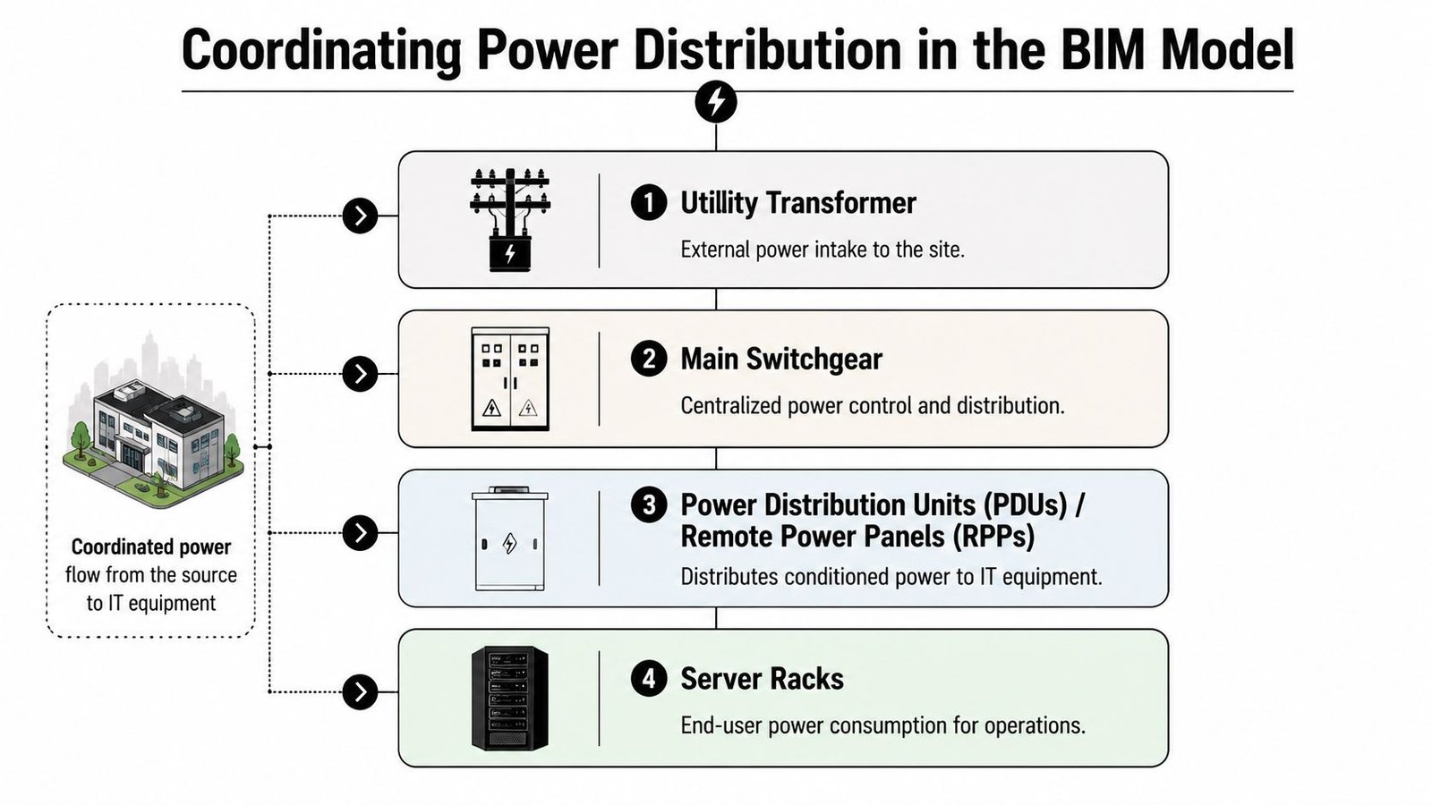
Start at the point of entry
The utility transformer and main switchgear need real geometry, not placeholders. The model should show:
- Equipment footprints: Actual dimensions from the selected basis of design or approved vendor information.
- Working clearances: Space needed for operation, code compliance, and maintenance.
- Bus duct routing: Entry and departure paths with turns, elevation changes, and support logic.
- Access zones: Paths for equipment replacement, breaker servicing, and safe front and rear approach where required.
If the main electrical room is still conceptual, the rest of the electrical coordination model is unstable.
A lot of teams underestimate this by focusing on room area but not routing consequence. In data center MEP Revit workflows, room planning only becomes useful when linked to actual distribution paths and access envelopes.
A strong upstream reference for this is disciplined electrical load calculation planning, because equipment arrangement and routing don't stand alone. They depend on the actual distribution strategy.
UPS, PDUs, and busway need buildable geometry
UPS systems can't be modeled as generic blocks. Their footprints, maintenance zones, ventilation requirements, and support conditions affect both architecture and structure. Floor loading review needs to happen before equipment specification is treated as settled.
Then comes distribution to the white space. Whether the project uses underfloor conduit, overhead cable tray, or busway, the decision changes slab penetrations, raised floor organization, overhead trade stacking, and hanger layout.
Don't release steel until the support logic for overhead busway is modeled. The busway itself is only part of the problem. Hanger spacing, attachment points, and maintenance clearance are what usually create the conflict.
What the power model must show
A production-ready power model should include these essential elements:
| Power element | What must be modeled before construction |
|---|---|
| Utility entry | Transformer location, access, and route into switchgear |
| Main switchgear | Exact footprint, clearances, and bus duct interfaces |
| UPS systems | Actual dimensions, service zones, and structural review inputs |
| PDUs and RPPs | Room placement and distribution relationship to rack zones |
| Busway or conduit | Full routing, elevations, supports, and crossing logic |
If one of those is still schematic, the model isn't ready.
Data Center Cooling System Coordination
Cooling coordination fails when teams treat it like standard HVAC with tighter tolerances. It isn't. The cooling system in a data center is part thermal strategy, part space claim, and part structural problem.
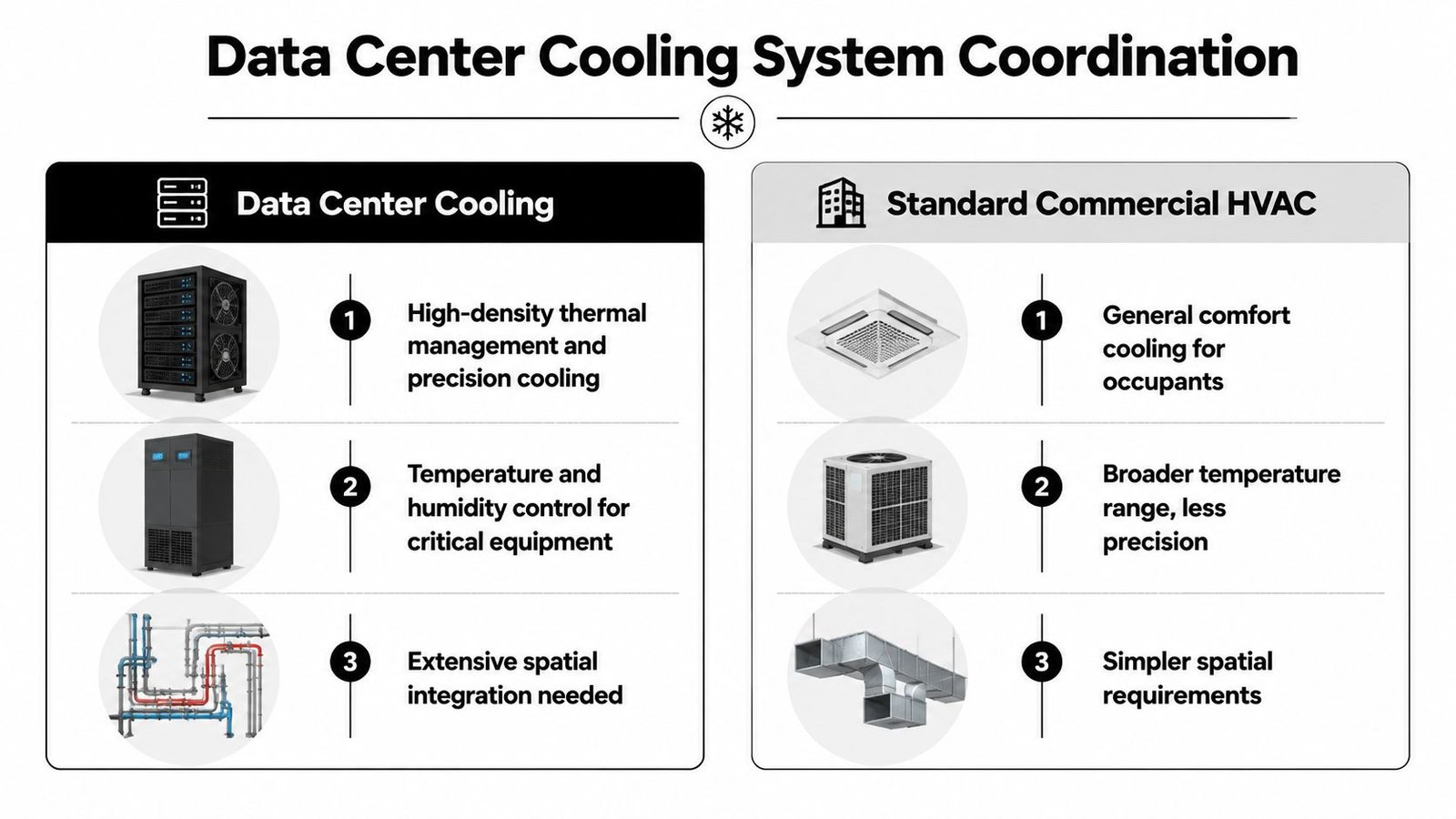
CRAC and CRAH placement must drive the room
CRAC and CRAH units need to be modeled with exact footprints, connection points, and service clearances. More importantly, the model has to represent how they actually support the air strategy. Hot aisle and cold aisle containment can't be coordinated as an architectural afterthought once equipment is “roughly in place.”
If containment, return paths, and unit placement are developed separately, teams often discover that the access aisle is wrong, the unit service side is blocked, or the overhead path needed for another trade has already been consumed.
For firms refining their mechanical production stack, a repeatable HVAC system design workflow helps because data center cooling depends on consistency in family content, connection logic, and parameter discipline. Bad content creates bad coordination.
Redundant piping has to be fully routed
Cooling models often become misleading in this situation. The primary loop is detailed. The backup loop is implied.
That doesn't work. Redundant chilled water piping must be routed as actual geometry. Beam crossings, deck offsets, valve access, insulation thickness, and penetration grouping all depend on both loops existing in the model at the same time. If only one loop is present, clash detection is giving a false sense of control.
Coordination rule: If the backup loop isn't modeled, it doesn't exist for construction planning.
Roof and structure need submittal-grade inputs
Cooling towers, condensers, and associated rooftop support conditions need structural review based on actual equipment information, not generic assumptions borrowed from commercial projects. The roof framing may work for one equipment package and fail for another with different point loads, footprint, or maintenance zones.
Use a simple review gate before release:
- Confirm selected equipment before finalizing support design.
- Verify operating and maintenance weights against structural assumptions.
- Coordinate access paths for installation and future replacement.
- Check connection routing back into the building envelope before roof openings are fixed.
Cooling models become reliable when they stop representing intent and start representing commitment.
Modeling Cable Management Before Installation
Cable management is one of the easiest systems to underestimate because it sits at the edge of disciplines. Electrical assumes IT will define it. IT assumes the trades can work around it. Coordination teams get left with a partial scope model that looks clean only because a major system is missing.
That's a mistake. In many facilities, cable tray is one of the dominant overhead users of space.
Overhead tray is not schematic scope
If overhead tray exists, it must be modeled with actual width, depth, elevation, bends, drops, and support locations. A single centerline route tells you almost nothing useful during clash detection. It won't reveal hanger conflicts. It won't expose tray depth collisions with lighting or sprinkler mains. It won't show whether access zones at equipment are being blocked.
When teams run coordination without complete tray geometry, they aren't coordinating. They're sequencing surprises.
The same applies to tray supports. The tray may clear a duct in section, but the support rod or trapeze may land exactly where another trade needs its own attachment. That's why hanger logic belongs in the federated model for serious overhead coordination.
Underfloor routing needs the same discipline
Raised-floor projects create a second coordination environment that's often even less mature than the ceiling space. Underfloor cable pathways compete with airflow strategy, pedestals, conduits, and transitions up to the rack line.
A good coordination review in this zone should answer three questions:
- Where does air need to move freely?
- Where do power and data need fixed pathways?
- Where do penetrations rise through the floor panel system?
If the model can't answer those clearly, the raised floor package shouldn't be released.
What should be fixed before the floor goes in
The minimum cable management decisions before installation are these:
- Overhead tray routes and elevations: Not conceptual, not deferred.
- Tray width and depth: Sized to the actual planned system, not a placeholder.
- Support locations: Coordinated with structure and other overhead trades.
- Underfloor pathways: Aligned with airflow and equipment layout.
- Panel penetration points: Located before raised floor procurement and installation.
Manual field layout after the floor is in place usually creates a messy result. Panels get over-cut, airflow gets compromised, and future maintenance becomes harder than it should be.
Fire Suppression Coordination for Data Centers
Fire suppression in a data hall needs a different coordination mindset from standard commercial sprinkler work. The issue isn't just pipe routing. It's system performance in a crowded, high-consequence environment.
Clean agent systems need spatial precision
Most server rooms use clean agent suppression rather than relying only on wet-pipe sprinklers. That changes the BIM task. Instead of a relatively familiar sprinkler layout problem, the team is coordinating small-diameter pipe networks and nozzle locations that depend closely on room geometry, equipment arrangement, and airflow conditions.
Nozzle placement can't be treated as a late overlay. If cable tray fills the intended discharge zone or a containment element redirects conditions in the room, the suppression layout may no longer work as intended. That's why the nozzles, branch lines, and overhead conflicts need to be visible in the model while the rest of the ceiling zone is still movable.
In data halls, suppression coordination isn't complete when the pipes fit. It's complete when the nozzles are placed where the room can actually perform as designed.
Underfloor protection changes the floor zone again
Some facilities also protect the underfloor plenum. That adds more pipe, more supports, and more competition with cable and airflow distribution below the raised floor. If that scope is not present in the federated model, the underfloor zone will appear far cleaner than it will be in reality.
Standard sprinkler areas still need equipment-aware layout
Electrical rooms, UPS rooms, and adjacent support spaces may still use standard wet-pipe systems. Those areas often get less attention because they feel familiar. They shouldn't. Head locations still need to respect equipment clearances, access paths, and architectural constraints. On data center projects, “standard” rooms still sit inside a highly constrained building.
The Pre-Construction BIM Coordination Gates
A data center model becomes useful when it controls release decisions. Until then, it's still just a reference file.
The preconstruction phase should lock down land, design, materials, labor, and equipment costs, then convert those inputs into a milestone-based schedule before field work begins, as described in Broadstaff's overview of the data center construction process. For BIM teams, that means defining hard coordination gates that the project must close before site work gets ahead of the model.
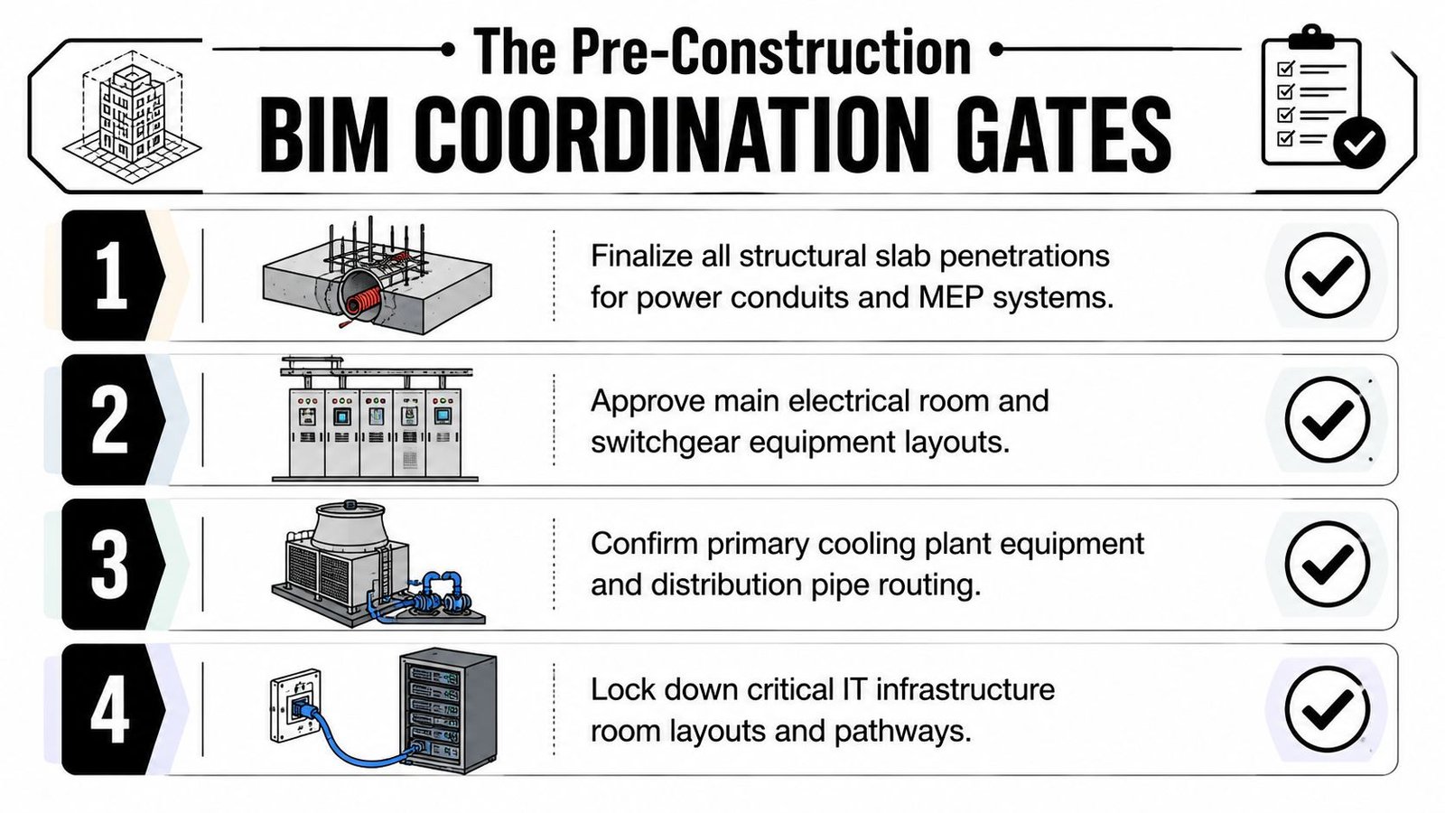
Gate one includes penetrations and structure
Every slab penetration for conduit, cable, piping, suppression, and drainage needs a defined location and size before pour sequencing moves forward. That schedule should come directly from the coordinated model, not from a manual spreadsheet assembled after the fact.
If the structural engineer is reviewing one penetration set while trades are coordinating another, the project has already created a control failure.
Gate two includes equipment truth
Placeholder weights are not good enough. Major equipment should be checked against approved submittals before structural assumptions are treated as final. If the actual UPS, switchgear lineup, CRAH unit, or transformer changes the loading condition, that needs to be caught before procurement and installation planning are locked.
Gate three fixes the raised floor height
Raised floor height determines underfloor volume, cable capacity, transitions, and the relationship between slab and finished floor. Teams sometimes leave it flexible for too long because it feels adjustable. It isn't. Once the floor package is bought and support details are set, flexibility is gone.
Gate four closes the overhead zone
All major overhead systems need to be coordinated to a defined clearance below the deck before structural steel is released.
A useful gate review looks like this:
- Penetration package approved
- Equipment weights verified
- Raised floor height fixed
- Overhead trade stack resolved
- Access and maintenance zones confirmed
That's what a construction-ready hyperscale data center BIM model should support. Not a prettier coordination meeting. A safer release decision.
Common BIM Coordination Failures and Fixes
Most failures on data center projects are predictable because the same shortcuts show up again and again.
The repeat offenders
- Cable tray is missing from the federated model: Add full tray routing and supports before overhead clash detection starts. Otherwise the clash report is incomplete by definition.
- UPS weight is based on a placeholder: Require a QA checkpoint where structural review is tied to equipment submittals, not assumptions.
- Redundant systems are shown as a single run: Model A and B paths as separate, clash-detectable systems.
- Penetration schedules are created manually: Extract them from the coordinated model to reduce transcription mistakes.
- Raised floor height stays open too long: Fix it early enough for underfloor routing and panel penetrations to mean something.
- Clean agent nozzles arrive late to coordination: Add suppression geometry before overhead zones are considered resolved.
The underlying cause
These aren't software failures. They're production failures.
Usually the problem is weak BIM execution planning, inconsistent content standards, or missing decision checkpoints between design, vendor inputs, and coordination release. The correction is almost always the same. Tighten templates, define model readiness criteria, and stop calling a model coordinated when key systems are still schematic.
Build with Certainty
The construction of data center projects rewards one thing above all else. Predictability.
A strong model doesn't just help teams visualize the building. It fixes routing decisions before they become field conflicts, protects margin by reducing rework, and gives the site team something they can build with confidence. That's the difference between using BIM as presentation and using it as production control.
The standard should be simple. By the time construction starts, the model should already show the penetrations, support logic, clearances, redundant routes, floor elevations, and equipment realities the trades will live with in the field. If it doesn't, the job is still being designed.
Good data center construction documents come out of that discipline. So do cleaner RFIs, better permitting prep, stronger QA, and more reliable turnover.
If your team needs help tightening data center BIM coordination, BIM Heroes supports firms with disciplined MEP coordination and BIM production workflows built for delivery, not just modeling. You can explore their MEP coordination and BIM production support and reach out when you need a stronger production system behind your next data center job.