Meta description: Learn what a SIPs BIM model must show for permit review and fabrication handoff, including panel layout, roof documentation, MEP coordination, and manufacturer QA gates.
The problem usually shows up at the worst possible time. The permit set is out, the project team thinks the envelope is resolved, and the SIP fabricator asks for the model or panel layout so they can start fabrication. Then the RFIs begin.
The walls were modeled as generic assemblies. Panel breaks were never coordinated. Rough openings don't match the manufacturer's header logic. Electrical chase locations were left for “later.” Fabrication stops while the architect and engineer push information back into a model that should have carried it from the start.
That's the gap on most SIP projects. The permit set may be good enough for design intent, but it isn't specific enough for manufacturing. If you're using SIPs for walls, roof panels, or floor assemblies, the model has to do two jobs at once. It has to support permit review, and it has to support fabrication without a second round of clarification.
The Handoff Failure Where SIP Projects Break Down
The failure usually starts after permit submission, not during design. The architect has a clean envelope model. The engineer has signed off. Then the SIP manufacturer asks a simple production question, and nobody can answer it from the model.
A SIP project breaks at handoff when the BIM file shows design intent but not fabrication intent. The wall looks resolved on screen, yet the model does not define panel breaks, spline conditions, bearing points, rough opening logic, or chase locations. At that point, the permit set is no longer the problem. The missing manufacturing information is.
SIPs are factory-cut components. That changes what the model has to carry before the job reaches the fabricator. A generic Revit wall type can show overall thickness and finish layers. It cannot tell the manufacturer whether a 7 foot 4 inch window lands inside one panel, forces a panel joint at the jamb, or needs a different header build-up to match the supplier's standard.
That is where teams lose time and create RFIs. The permit drawings may show the right dimensions overall, but the fabrication team still has to stop and ask how the panels are supposed to be broken, joined, and reinforced.
Practical rule: If the model cannot show where each SIP starts, stops, opens, and connects, it is not ready for permit handoff on a SIP project.
The teams that avoid rework make one decision early. They treat the BIM model as a manufacturing input before permit submission, not as a permit package that gets "worked out later" during shop drawing review. That single shift removes a large share of the back-and-forth that delays procurement, fabrication, and installation.
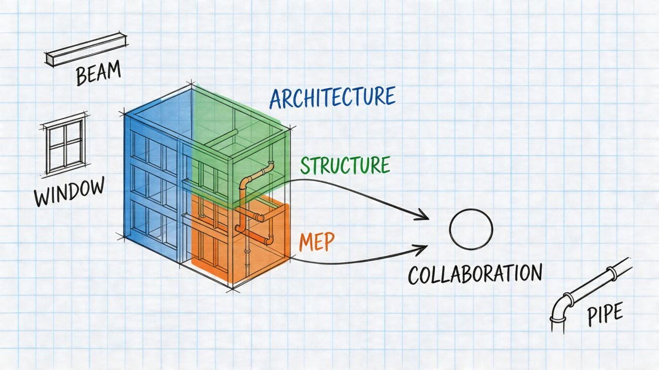
Why SIP Projects Demand a Different Modeling Approach
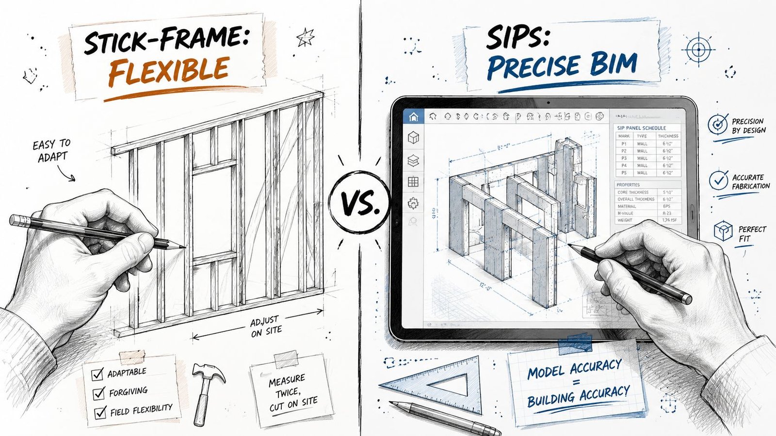
A SIP job can look clean in plan and still fail the minute the manufacturer starts panel takeoff. The problem is usually not the overall design. It is that the model was built like a conventional wall package instead of a cut-file input.
Stick framing gives the field crew room to absorb small misses. SIP construction pushes those decisions upstream. Panel size, joint location, spline condition, bearing, and opening support all need to be resolved in the model early, because those choices affect what gets fabricated, shipped, and set.
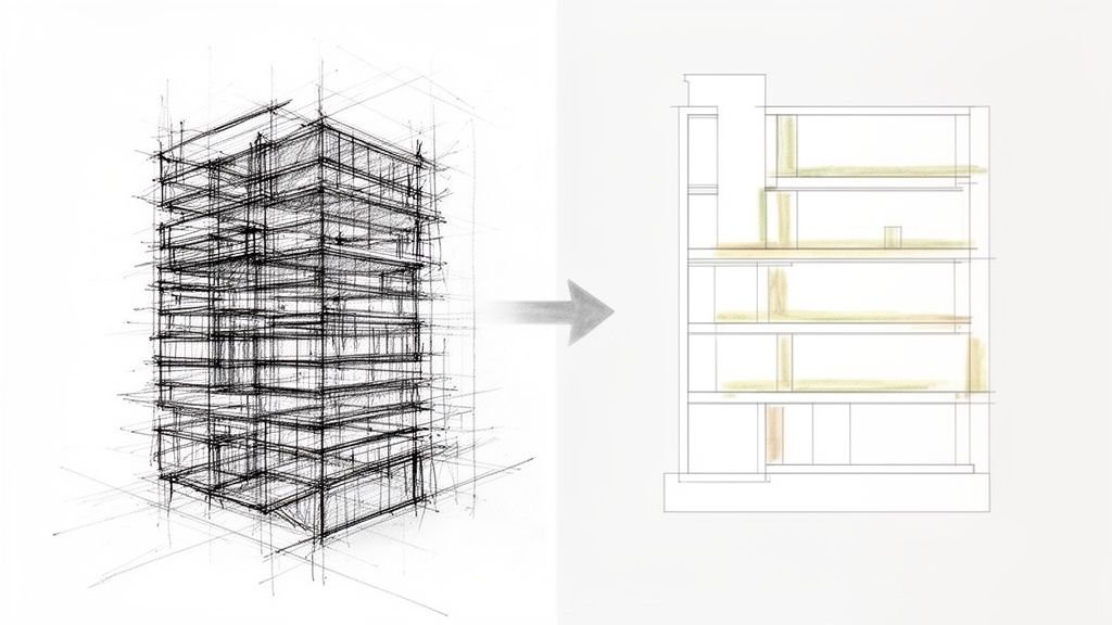
Model panel reality, not nominal wall thickness
For SIPs BIM model permit fabrication work, a generic wall type is only a placeholder. It can show assembly depth. It does not tell the production team how the wall will be broken into panels, where joints fall, or whether openings fit the manufacturer's layout rules.
That distinction matters before permit submission, not after. If panelization is deferred until shop drawings, the permit dimensions, structural assumptions, and opening locations are often based on geometry the fabricator cannot use without revisions. That is where RFIs start. Then the redraws follow.
The model should already reflect the intended panel widths, joint strategy, and opening logic closely enough that the permit set and the fabrication review are working from the same dimensional intent.
Joints and headers change the buildable dimension
SIP walls are governed by connection logic as much as overall length. A wall run may dimension correctly at the building level and still fail at production level because the panel joints were never defined. Once the spline type, joint treatment, and bearing condition are selected, the layout can shift enough to affect corner returns, opening offsets, and roof bearing alignment.
Openings create the same problem. Doors and windows are not just voids cut into a panelized wall. They bring header requirements, jamb conditions, fastening limits, and rough opening rules that need to match the supplier's system. If those items stay generic in the permit model, the architectural opening schedule and the panel shop drawings drift apart.
A clean-looking model is not the same as a buildable one.
If the model ignores joint logic, every panel-to-panel connection becomes a dimension bust on site.
Teams that keep SIP projects out of rework treat the model as a controlled handoff to manufacturing. Before permit issue, they check three things: every panel run has a defined break strategy, every opening has a resolved support condition, and every dimension the permit team is publishing can survive fabrication review without being reinterpreted.
Permit Set Requirements for SIP Construction
Permit reviewers don't just need to see a wall on plan. They need to see a defined structural system.
For SIP construction documents permit packages, the permit set should make the panel assembly legible to the reviewer and traceable to the engineered system being supplied. If your drawings leave the SIP scope generic, you're asking the jurisdiction to approve a structural envelope without enough information to verify what it is.
What needs to appear on the drawings
At minimum, the permit set should clearly identify:
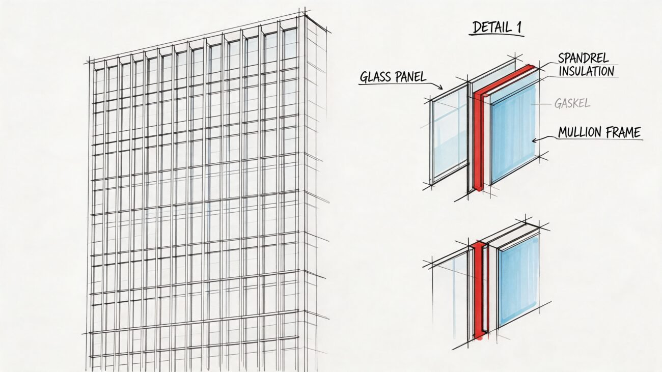
- Panel type and assembly definition. Show the SIP wall or roof assembly with its thickness, facing material, and structural designation.
- Evaluation report reference. If the jurisdiction expects a recognized testing or code evaluation listing, place that report reference in the wall type legend, general notes, or assembly notes where plan review can find it quickly.
- Engineered responsibility. SIP walls and roof panels used structurally should be tied to the licensed structural engineer's design package, stamped calculations, or engineered drawings.
- Panel layout intent. Even if the final shop package comes later, the permit set should already show that panelization has been considered and coordinated.
What usually gets missed
The missing piece is often the layout document itself. A permit set may show exterior dimensions, structural notes, and wall sections, yet still omit the information that tells the reviewer and fabricator how the system is broken into panels.
That's why the panel layout plan is so important. It closes the gap between “this building uses SIPs” and “this is how those SIPs are organized, sized, and connected.”
If your local authority will accept manufacturer span tables for standard conditions, confirm that early with the AHJ. Don't assume. The acceptance threshold varies, and late clarification can force a permit revision.
The Critical Details for Your Panel Layout Plan
The panel layout plan is the working document that either protects the job or creates the next round of RFIs. If it's vague, fabrication pauses. If it's precise, the handoff becomes routine.
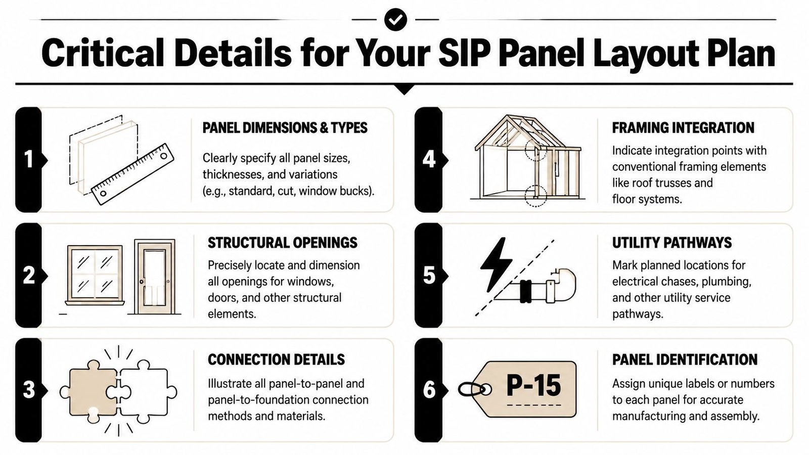
Treat the panel layout as the single source of truth
Architectural floor plans are not enough. Fabricators work from a panel logic, not from design intent alone. That means your SIP panel BIM coordination needs to lock down the items below before issue.
- Individual panel dimensions. Each panel should be labeled with its width, height, thickness, and unique panel mark.
- Panel numbering. The numbering sequence should be stable and tied to a schedule or key plan so the field team can match fabrication output to installation order.
- Spline joint locations. Show every panel-to-panel joint and identify the connection type used in that location.
- Opening coordinates. Locate openings from the panel edge or another fabrication reference, not from the architectural grid.
- Header information. Tie each opening to the structural header requirement in a way the fabricator can read without guesswork.
- Service pathways. Show all required electrical chases and any planned penetrations that affect fabrication.
For teams building repeatable workflows, a dedicated panel fabrication workflow helps because it forces these decisions before the issue date, not after the manufacturer's review comments arrive.
Dimension like a fabricator, not like a permit drafter
This aspect often causes many otherwise competent sets to fail. Grid-based dimensions help an architect align plans. They don't help a SIP plant cut openings accurately.
The fabricator needs dimensions that reference the panel itself. If the opening is measured from a control line that doesn't survive panelization, somebody has to reinterpret the drawing. Reinterpretation creates errors.
The safest panel layout is the one that leaves nothing for the shop to infer.
Build in review points before release
Before issuing the layout, run a compact QA pass:
| Check item | What to confirm |
|---|---|
| Panel marks | Every panel is uniquely tagged and readable |
| Joint logic | All spline locations and types are shown |
| Opening dimensions | Measured from panel edge or fixed fabrication reference |
| Header callouts | Aligned with structural notes and details |
| Chases | Outlet, switch, and feed path assumptions are resolved |
That review takes less time than sorting out a frozen fabrication release.
Documenting SIP Roof Panels Correctly
Roof panels need their own documentation logic. Teams often carry over wall documentation habits and miss the structural consequences.
A SIP roof panel isn't just a roof assembly with insulation baked in. It is a spanning structural component. Structure magazine reports that a 12-1/4-inch SIP spanning 8 feet can carry up to 106 psf, and a 6-1/2-inch SIP roof panel can carry up to 80 psf at L/180 deflection in its discussion of SIP behavior in residential and commercial construction. That load behavior is exactly why the documentation has to be explicit.
Show span direction and support conditions
On roof plans, span direction should be unambiguous. Use arrows. Don't assume the installer or fabricator will infer intent from geometry alone.
The support condition also needs to be legible. Whether the panel spans ridge to eave or between other structural supports changes connection detailing, bearing assumptions, and panel orientation. A wrong assumption here isn't a minor field fix.
Coordinate the edges before the permit issue
Roof thickness often drives architectural detailing more than teams expect. Once the roof panel thickness is set, it affects:
- Eave depth
- Fascia build-up
- Rake and gable end conditions
- Parapet and coping transitions
- Ridge alignment with the supporting structure below
Those conditions should already be reconciled in the model. If they aren't, the permit drawings may show one roof edge while the fabrication package requires another.
A clean roof section is not enough if the plan, edge detail, and 3D model aren't all speaking the same language.
Coordinating MEP Systems in SIP Models
MEP coordination on SIP projects has to move earlier than is typically done. If you leave it to field coordination, you've already waited too long.
Electrical wiring in SIP walls depends on pre-cut chases. Mechanical penetrations have to be known before fabrication. Unlike a stud wall, you can't treat the panel core as flexible routing space and expect the building envelope to survive intact.
Finalize electrical intent before layout release
Outlet and switch locations can't stay schematic once the panel layout is being developed. The manufacturer needs those locations early enough to route horizontal and vertical chases in the correct panels.
That means the electrical designer, architect, and production lead need one coordinated checkpoint before fabrication review. If the reflected ceiling plan, power layout, and interior elevations are still moving, the panel package isn't ready.
A practical handoff includes:
- Confirmed receptacle locations tied to actual wall extents
- Switch positions that respect openings and panel breaks
- Vertical chase strategy coordinated with top or bottom feed assumptions
- Special systems identified before issue, not added by bulletin later
Teams that already run disciplined MEP coordination workflows usually adapt faster to SIP projects because they're used to resolving penetrations before field installation.
Penetrations need approval logic
Mechanical penetrations deserve the same level of discipline. HRV or ERV wall penetrations, duct sleeves, vent terminations, and major pipe penetrations should be included in the panel layout package before fabrication.
If a penetration is missing from the panel layout, the jobsite becomes the redesign location.
That's where warranty and structural risk enter the picture. Unplanned field cuts can affect the facing, the sealing strategy, and the structural behavior of the panel. Even when a modification is possible, it usually needs manufacturer review and may require an approved patch or revised detail.
The SIP Manufacturer Coordination Workflow
The manufacturer shouldn't enter the process after permit issue as a passive supplier. On a SIP project, they are part of the production workflow much earlier.
The coordination sequence works best when the manufacturer's system constraints are treated as design inputs. That includes panel size limits, spline options, typical connection details, chase routing constraints, and opening requirements. If you design around one system and switch suppliers later, the rework is real.
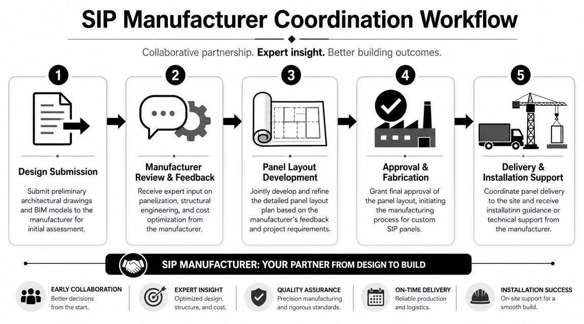
Put the manufacturer review before permit
This is the gate many firms skip. They assume permit comes first and fabrication review follows. On a SIP job, that order often creates avoidable RFIs.
Issue the model or the panel layout plan to the manufacturer while the permit set is still being finalized. Give them enough information to flag conflicts in panelization, opening assumptions, chase routing, and connection feasibility. Build that review window into the schedule as a required milestone.
The reason is simple. The Structural Insulated Panel Association cites a third-party study indicating that a properly trained SIP crew can cut framing time by 55% versus conventional wood framing in the Grand View Research market summary. That productivity only shows up when the fabrication drawings are accurate and coordinated.
Use a fixed handoff package
A reliable workflow usually includes these issue points:
- System selection. Confirm manufacturer, panel family, and core connection assumptions.
- Design model freeze. Lock exterior wall extents, opening sizes, and roof geometry enough to support panelization.
- Manufacturer review. Send the model and layout package for technical review.
- Comment resolution. Push all accepted revisions back into the permit set and model.
- Fabrication release. Issue approved panel information only after the comments are closed.
For firms working across prefab scopes, an off-site construction coordination process helps because it formalizes those gates and reduces late interpretation.
Manufacturer review isn't an optional courtesy. It's a QA checkpoint.
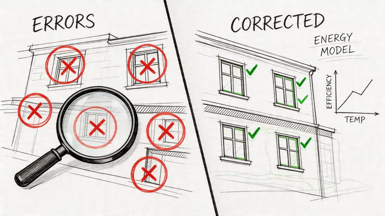
Common BIM and Drawing Errors to Avoid
Most SIP rework comes from a short list of preventable misses. None of them are exotic. They're production discipline problems.
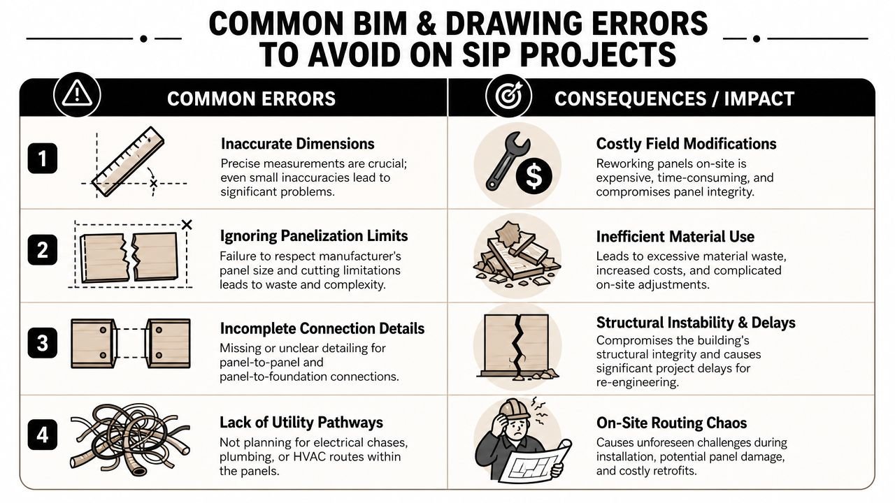
The errors that keep showing up
- Panel joints missing from permit drawings. If the set identifies SIP walls but never shows where the panels break, the reviewer and fabricator are looking at different documents.
- Overall dimensions ignore joint build-up. Plans look clean, but the realized wall length changes once the spline logic is applied.
- Openings are dimensioned from the grid. That works for architectural coordination and fails for panel cutting.
- Electrical chases are absent. The layout gets issued while power locations are still floating.
- Roof span direction isn't shown. The roof may be geometrically correct but fabrication-critical information is still missing.
- Roof edge details carry the wrong thickness. Fascia, rake, and parapet details were never updated to the actual SIP roof build-up.
- Manufacturer review was skipped. The team issued permit first and discovered system conflicts second.
Run one final pre-issue audit
Before permit submission or fabrication handoff, check the package against these questions:
| QA question | Pass condition |
|---|---|
| Are panel breaks shown where fabrication expects them? | Layout and plans agree |
| Do opening dimensions work from panel references? | No grid-only opening control |
| Are chase and penetration locations resolved? | Electrical and mechanical inputs are issued |
| Does the roof package show orientation and edge build-up clearly? | Span, thickness, and detail sheets align |
The fastest way to lose predictability on a SIP project is to let “generic for now” survive into the issue set.
Get Your SIP Project Production-Ready
Permit approval is not the finish line on a SIP job. The ultimate test is whether the model and drawing set can move into manufacturer review and panel production without a round of clarification, redlines, and last-minute geometry fixes.
Production-ready means the permit model already carries fabrication intent. Panel breaks are resolved. Opening control points match how the panels will be cut. Roof build-up, bearing conditions, and span direction are explicit. MEP penetrations and chases are no longer placeholders waiting on someone else to decide later.
That discipline protects margin. Every unresolved item left in the permit set tends to come back at the worst point in the schedule, when procurement is active, the manufacturer wants answers, and the design team is forced into rushed revisions. The cost is rarely one big failure. It shows up as RFIs, redraw time, delayed releases, and field fixes that should have been prevented in the model.
Teams that do well with SIPs treat BIM as a production control document, not just a permit deliverable. The handoff succeeds when the architect, consultant team, and manufacturer are all reading from the same geometry and the same assumptions before the set is issued.
If your workflow still models SIPs like a generic wall and leaves panel logic for later, fix that before the next permit submission.
If you're working through a live SIP project and want a second set of eyes on model setup, permit documentation, or fabrication handoff, BIM Heroes can help. You can also explore their architectural production services if you need Revit production support, QA structure, or a cleaner delivery workflow for SIP-based projects.