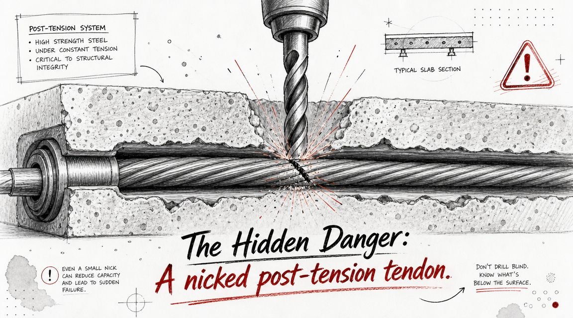
A plumber cores a post-tension slab for a new drain line, without checking the tendon layout. The bit catches a tendon, the cable is damaged, the structural engineer gets called to site, and the job stops while the team works out repair, liability, and who approved the cut.
That sequence usually doesn't start in the field. It starts weeks earlier, when MEP coordination post-tension slab work gets treated like a drawing overlay instead of a live, controlled workflow. On PT jobs, routing decisions, penetration approvals, model visibility, and issue tracking have to happen in a disciplined order. If they don't, the field team inherits uncertainty and solves it with a saw, a core drill, or an RFI written too late.
Process protects margin. The right workflow makes tendon constraints visible before routing starts, forces structural review before penetrations hit the permit set, and gives field teams a reliable record of what's approved and what isn't.
Meta description: A practical guide to MEP coordination post-tension slab workflows, including tendon layout inputs, BIM exclusion zones, penetration approvals, and field risk prevention on PT slab projects.
Introduction The Cost of Uncoordinated PT Slab Penetrations
On a PT slab project, one bad cut can turn a routine install into a structural incident. A severed tendon isn't a cosmetic problem, and it isn't a simple patch. It becomes an engineering event, a schedule problem, and often a claims problem.
That's why post-tension concrete MEP coordination has to start with constraints, not with convenience. If plumbing, ductwork, and conduit routes are laid out before the team has a real structural approval path, the model becomes misleading. People assume a route is acceptable because they can draw it, not because it can be built.
Practical rule: If a penetration hasn't been reviewed against the tendon layout and approved by structural, it isn't coordinated.
The teams that keep PT projects under control do a few things consistently. They request tendon information early. They turn no-go areas into visible modeled geometry. They maintain a live penetration schedule with ownership. And they stop field improvisation before it starts.
What Post-Tension Slabs Mean for MEP Routing
Post-tension slabs contain high-strength steel tendons that are stressed after the concrete gains strength. This isn't a fringe system. The Federal Housing Administration approved post-tension slabs in 1969, and one industry explanation notes that stressing begins once concrete reaches about 2,000 psi, with each tendon applying roughly 33,000 pounds of force in this post-tension slab overview. That's the operational reason a damaged tendon is a major event, not a punch-list item.
Banded and distributed tendons don't create a uniform routing field
In coordination terms, tendons usually behave like two different traffic systems. Banded tendons are concentrated tightly in one direction. Distributed tendons run perpendicular with wider spacing. If you think of one as a highway corridor and the other as local roads, you get the point: the slab doesn't offer a regular, predictable grid for MEP penetrations.
That matters because many routing errors begin with a false assumption that there's a repeatable clear zone across every bay. There isn't. Tendon paths shift with column layout, loading, geometry, and structural design decisions. A route that works in one bay may be unacceptable in the next.
No-penetration zones must be treated as hard geometry
On PT work, certain areas are entirely not available for casual routing. Around columns, slab edges, and tendon anchor zones, structural engineers often restrict penetrations tightly. Those restrictions have to appear in the model as exclusion volumes, not as buried notes or verbal cautions.
Use this as the baseline rule set:
- Columns: treat the surrounding slab area as restricted until structural defines what's allowed.
- Slab edges: assume tight limitations where anchorages and edge conditions control.
- Anchorage zones: never route by assumption near live ends or dead ends.
- Transfer areas and loaded regions: escalate early if routing pressure pushes into structurally sensitive zones.
If an MEP team starts laying out post-tension slab MEP penetrations before those zones are visible, they're routing blind.
What the Structural Engineer Must Provide
A PT slab coordination process falls apart when the structural package arrives as notes and intent instead of usable coordination inputs. Before serious MEP routing starts, the structural engineer needs to provide three things clearly and in a format the BIM team can act on.
The pre-flight checklist
First, the team needs tendon layout drawings. That means actual banded and distributed tendon paths, not just general slab framing sheets. It also means anchorage locations at slab edges, because edge conditions often control what's possible for sleeves, openings, and riser transitions.
Second, the structural engineer needs to define no-penetration zones and required clearances in a way the model team can build. A note that says “coordinate openings with structural” doesn't help the person routing sanitary mains in Revit. The modeler needs extents, boundaries, and review logic.
Third, there has to be a formal penetration approval process. Who submits. In what format. At what intervals. What gets approved in model. What has to appear on drawings. What status language is used when something is conditional.
A buried note won't run a PT project. A defined workflow will.
What to request if it isn't in the permit package
On many projects, the initial structural issue set won't include everything the MEP team needs for PT coordination. That's where teams lose time by assuming the missing information will appear before it matters. It usually matters immediately.
Request these items early:
- Detailed tendon plans: enough detail to model routing constraints accurately.
- Anchor zone information: especially where vertical distribution is planned near edges.
- Opening review criteria: including whether grouped penetrations need combined review.
- Approval submission format: markup set, penetration log, model views, or all three.
If your production team needs support building these structural constraints into a usable model environment, a dedicated BIM modelling services workflow is usually more effective than handing off scattered PDFs and expecting discipline-by-discipline interpretation.
The permit set may be sufficient for construction intent. It's often not sufficient for PT slab coordination.
Routing first and asking for approval later feels fast for about a week. Then rework starts.
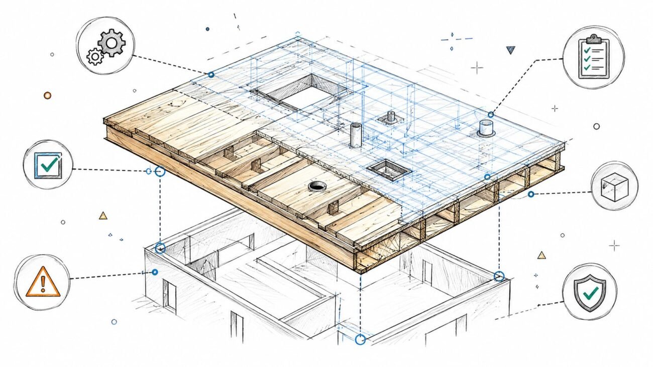
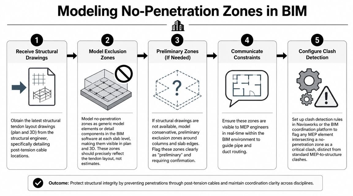
Modeling No-Penetration Zones in the BIM Model
A PT restriction that nobody can see won't control routing. The whole point of modeling no-penetration zones is to make structural constraints visible while MEP teams are placing systems, not after the clash meeting.
Build the zones as objects, not annotations
In Revit, the cleanest approach is to model no-penetration areas as generic model elements or another controlled category that displays in plan and 3D. The category matters less than consistency, visibility, and the ability to use it in views, filters, and clash rules.
Good zone modeling usually includes:
- Level-based placement: each slab level gets its own set of exclusion volumes.
- Readable naming: zone names that tie back to slab area, grid, or structural markups.
- View controls: color overrides so MEP designers can read constraints instantly.
- Status controls: issued, preliminary, revised, superseded.
The source should be the structural tendon layout, not a rough estimate from the MEP side.
Preliminary zones are still no-go zones
Sometimes the MEP team has to start broad routing before tendon plans are fully issued. In that case, model conservative preliminary zones around columns, slab edges, and likely anchor regions. Label them clearly as preliminary, but treat them as real restrictions until they're replaced with confirmed geometry.
That one move prevents a common failure mode: the team fills a risky area with pipe and duct because “it was open in the model,” then discovers later that the area was never available.
Make PT clashes different from ordinary clashes
A duct crossing a beam and a sanitary sleeve landing in a PT exclusion zone are not the same class of issue. Your clash rules should reflect that. In Navisworks or your chosen coordination platform, any intersection between MEP elements and no-penetration volumes should be flagged as critical.
That gives the BIM coordinator a clean triage structure:
| Clash type | Response |
|---|---|
| Standard MEP-to-MEP | Discipline coordination |
| Standard MEP-to-structure | Usual clash review |
| MEP-to-PT exclusion zone | Immediate structural review |
That separation matters. PT conflicts shouldn't get lost in a weekly list of ordinary coordination items. A dedicated clash detection workflow for constructability review helps because it turns the modeled zones into an active QA system, not just colored geometry in a 3D view.
Drain and Waste Routing on PT Slabs
Plumbing is where PT slab coordination gets real. Gravity systems don't care about your preferred route. They need slope, and slope pushes the team toward slab crossings, drop points, and elevation changes that often collide with tendon paths.
For PT slab plumbing coordination, every through-slab drain penetration should be treated as an individually reviewed event. If the structural engineer allows it, the location still has to maintain the required clear distance from tendons. If the route can't do that, the route changes.
The sleeve is never just the pipe size
A common miss is sizing the sleeve for the carrier pipe only. That's not enough on PT work. The sleeve has to accommodate the pipe, any insulation where applicable, and the structural clearance requirement around the sleeve position once it's shifted off tendons.
If the line needs to move to fit between tendon paths, the envelope changes. That's where a “works on paper” sleeve becomes unbuildable in the slab.
Use a simple coordination check before submission:
- Confirm the pipe outside diameter
- Add insulation if the system requires it
- Test the sleeve envelope against the approved tendon clearances
- Dimension the penetration by grid and offset, not by eye in plan
- Submit the exact location, not a conceptual corridor
Under-slab routing is often the cleaner answer
On slabs-on-ground, plumbing teams sometimes have a better option. The Post-Tensioning Institute notes that PT slabs-on-ground are typically 7.5 to 12 inches thick and are used as shallow foundations to manage movement in expansive soils on its slab-on-ground application page. Where under-slab routing is feasible, that option can remove a large portion of the through-slab penetration risk.
That doesn't mean under-slab is automatic. Site utility elevations, maintenance access, sequencing, and civil coordination still matter. But as a routing strategy, it often reduces structural approval pressure significantly at the ground floor.
If a drain can go below the slab cleanly, that option usually deserves to be tested before the team starts negotiating through-slab penetrations.
A strong plumbing lead will test both paths early. One path may save a few feet of pipe. The other may save weeks of coordination churn.
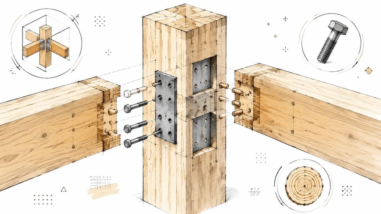
Mechanical and Electrical Penetrations
Mechanical and electrical teams sometimes get into trouble on PT jobs for opposite reasons. Mechanical openings are often large enough that everyone notices them late. Electrical penetrations are often small enough that people assume they don't matter. Both assumptions create risk.
Large duct openings need early structural ownership
Vertical supply and return air openings through PT slabs have to be fixed early enough that the structural engineer can review the opening size, location, and required detailing around it. These aren't “coordination later” items. They influence how the slab performs and how the opening edges are handled in the documents.
A technical post-tension slab design course reports that PT slabs often reduce slab thickness by 30% to 50%, reduce concrete volume by 10% to 20%, lower reinforcing costs by 20% to 30%, and can achieve average bay spacing of 25 to 30 feet without increasing slab thickness in this post-tension slab design reference. That efficiency is exactly why large, uncoordinated openings are disruptive. The slab is doing more with less material. You can't casually carve into that logic.
Small conduit sleeves become a big problem when grouped
Electrical coordination fails differently. A single conduit sleeve may look harmless in isolation. A dense bank of sleeves at a riser, panel room, or telecom drop becomes cumulative section loss. Structural review has to consider the cluster as a group, not as a series of unrelated tiny holes.
That means the electrical model can't scatter individual sleeve requests across separate markups and expect meaningful review. Group them. Dimension them together. Show the structural engineer the actual condition.
A quick field-minded checklist helps:
- Single sleeve: still review it, especially near restricted zones.
- Sleeve bank: submit as one grouped condition.
- Large feeder corridor: coordinate route alternatives before fixing the opening.
- Mixed trade cluster: plumbing, power, and low-voltage penetrations should be reviewed together if they land in the same slab area.
No penetration is “too small to matter” on a PT slab. Some are just too small to get noticed until they've accumulated into a bad decision.
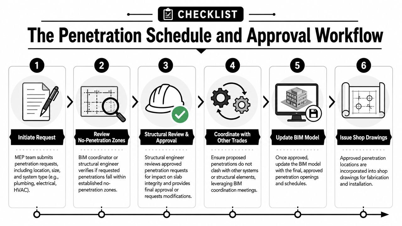
The Penetration Schedule and Approval Workflow
The penetration schedule is the control document for the whole PT slab process. Without it, approvals become scattered across emails, markups, model comments, and meeting memory. That's how teams lose track of what was approved, what changed, and what still needs structural sign-off.
What the schedule needs to track
The BIM coordinator should own a live penetration log that captures each through-slab opening by discipline, size, exact location, slab level, and approval status. Don't rely on cloud issue pins alone. They're useful, but they're not a stable project record.
At minimum, the schedule should include:
- Penetration ID
- Level and grid reference
- Offset dimensions
- Discipline
- Opening or sleeve size
- Submission date
- Structural response
- Current status
- Revision note if rerouted
The approval loop should be predictable
The best PT projects use a batch review cycle. Weekly works well on fast jobs. Biweekly can work where design changes are steadier. What doesn't work is sending one request at a time all week, then dumping a large unresolved set right before permit issue.
The loop is straightforward:
- MEP teams identify candidate penetrations.
- BIM coordinator checks them against modeled exclusion zones.
- Approved-for-submission items go to structural in a batch.
- Structural returns each item as approved, approved with conditions, or rejected.
- Rejected items are rerouted and tracked as open issues.
- Model, schedule, and drawing outputs are updated together.
That last part matters. If the model changes and the schedule doesn't, the project record is already drifting.
Tie approval status to deliverables
A penetration shouldn't move into issued documentation unless its approval status supports that move. That means permit and construction outputs need a clean link back to the log and the model state. If your team is producing coordinated fabrication or installation information, the same discipline is needed in shop drawing development and release workflows.
Approval isn't a comment in a meeting. Approval is a traceable status attached to a specific opening at a specific location.
When teams run this process consistently, RFIs drop because the questions get answered before they reach the field. More importantly, crews stop making assumptions based on partial information.
Common Coordination Failures on PT Slab Projects
Most PT slab problems are predictable. They show up when the team skips sequence, weakens model controls, or lets field decisions outrun approved documents.
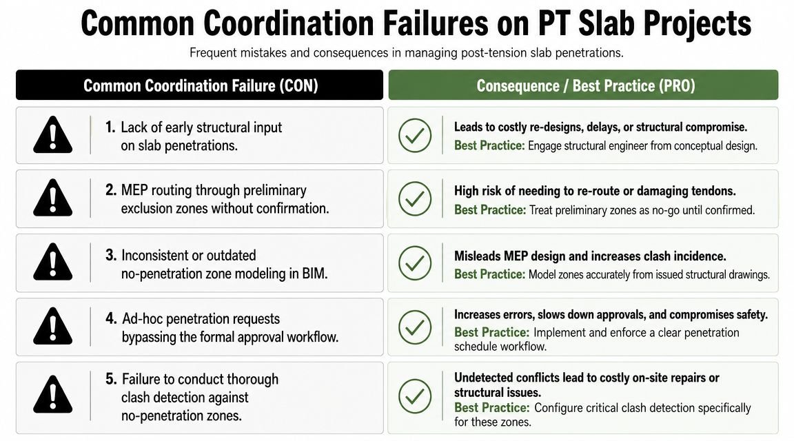
Run the pre-mortem before coordination starts
Use these failure points as rules in the BIM execution plan for structural MEP coordination post-tension work.
- Routing starts before tendon layouts arrive: freeze slab-level routing in sensitive areas until structural issues usable tendon information.
- No-penetration zones aren't modeled: create exclusion volumes before real coordination begins.
- Sleeves are sized for pipe only: verify the full penetration envelope, not just nominal pipe diameter.
- Large duct openings never reach structural sheets: push them into structural review early enough to appear in issued documents.
- Grouped conduits get submitted one by one: combine clustered penetrations so structural sees the actual condition.
- The penetration log has no owner: assign it to the BIM coordinator and update it after every review cycle.
- Field crews cut based on convenience: place a clear note in the documents that no field penetration is permitted without written structural approval.
Renovation work gets riskier when records are weak
Old coordination mistakes resurface later, making GPR services essential. Renovation teams need GPR to locate embedded PT cables before drilling or cutting, and anchor zones require specialized field identification rather than generic concrete assumptions, as described in this article on how GPR helps locate post-tension cables and anchor conditions. If design coordination is loose on day one, someone pays for forensic verification later.
That's the key operational takeaway. PT slab coordination isn't just about avoiding clashes in Navisworks. It's about protecting the project from bad field decisions, permit rework, and schedule loss caused by preventable uncertainty.
If your team is tightening its PT slab workflow, BIM Heroes can help with the production side that usually breaks first: model setup, clash logic, penetration tracking, drawing alignment, and coordination support that stays consistent across delivery cycles. If you need a reliable process for MEP coordination on slab-heavy projects, contact BIM Heroes for MEP coordination support.
Suggested category: MEP Engineering