Meta description: Revit MEP family errors usually start at the connector level. Learn how wrong system classification, flow direction, size parameters, origin placement, and domain settings break system connectivity, and how to fix them.
Suggested category: MEP Engineering
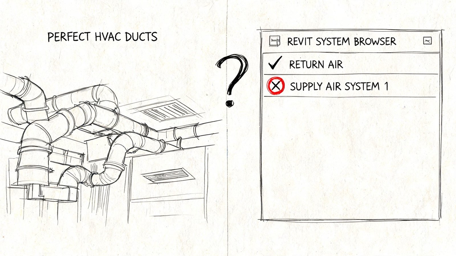
A duct run can look perfect in plan, section, and 3D, yet still fail where it matters. The System Browser splits it into separate branches. Flow totals don't add up. Pressure drop analysis refuses to behave. You inspect the model for gaps, nudges, bad snaps, and routing issues, and everything looks clean.
That usually sends people deeper into the project model. Wrong place.
When geometry looks right but revit mep system connectivity is broken, the problem is usually inside a family. Not in the duct type. Not in the pipe system settings. Not in the view. A connector is misclassified, reversed, offset, hardcoded, or living in the wrong domain. The family is lying to the project, and Revit is only doing what that data tells it to do.
This is the diagnostic inversion that saves time. Start in the family editor first, especially if the family came from a manufacturer library, an old office standard, or a quick internal copy that was never audited.
The Diagnostic Principle of Revit MEP Connectivity
A duct run can snap cleanly, tag correctly, and still fail the moment you check the System Browser. I see that pattern most often when teams keep hunting in the project model even though the fault is sitting in the family editor.
What Revit is actually reading
Revit does not judge connectivity by touching geometry. It reads connector data. In a loadable MEP family, each connector carries the logic that tells Revit what system it belongs to, which way flow moves, what it can connect to, and whether its size can coordinate with the hosted geometry.
If that connector data is clean, the project behaves like a system model. If it is wrong, the project only looks coordinated.
That is why the family editor is the primary troubleshooting environment for connectivity failures. For teams building coordinated models in MEP in Revit workflows, the expensive mistakes usually start before the family is ever loaded into the project. By the time the issue shows up in schedules, flow paths, pressure calculations, or disconnected branches, the bad decision has already been baked into the connector.
Practical rule: If the model appears connected but the system acts broken, open the family before you redraw anything in the project.
The failure pattern that wastes production time
The time loss usually follows the same sequence. A technician sees a clean physical join, assumes the geometry is valid, and starts checking routing preferences, system settings, snaps, or view behavior. None of that fixes the result because the project is only reporting what the family connector allows.
Typical signs are easy to miss at first:
- The element connects graphically: Duct, pipe, or conduit attaches in the view.
- System logic breaks anyway: Revit splits the network, leaves connectors open, or refuses to include the element in the expected system path.
- Project-level edits fail: Type swaps, trims, redraws, and reconnect attempts change the appearance but not the underlying logic.
- The family is the source: One or more connector properties are authored in a way that conflicts with the intended service.
That distinction is important because a bad family can waste hours across an entire model. The visible join gives the team false confidence, while the connector definition blocks analysis, scheduling, and system continuity. In practice, the fastest fix is usually not in the project at all. It is a connector-by-connector audit inside the family editor.
Fixing Incorrect Connector System Classifications
If you only check one thing first, check System Classification. This is one of the most common Revit MEP family errors because the family can still appear to connect even while Revit refuses to treat it as part of the intended system.
What goes wrong
A connector classified as the wrong system type creates a hard logic break. The geometry may snap, but the system won't resolve correctly.
Common examples:
- A VAV box with generic air classification: It attaches to ductwork in the model, but won't behave like part of a supply air system.
- A fan coil with vague hydronic connectors: If the piping connectors are set to an undefined or incorrect class, Revit won't build the hydronic tree correctly.
- A plumbing fixture with the wrong waste or water classification: The element may sit in the run, but the browser and calculations treat it as something else.
What to check in the family editor
Open the family, select each connector, and inspect the Properties palette. Don't assume paired connectors were set correctly just because one of them was.
Use this quick check:
| Connector check | What to confirm |
|---|---|
| Intended service | Supply air, return air, exhaust, sanitary, hydronic supply, hydronic return, and so on |
| Connector-by-connector review | Each connector has its own classification |
| Mixed-service equipment | Water, air, and electrical connectors are all set independently |
If a family "almost works," that's often a classification issue. Revit can host it, place it, and display it correctly while still rejecting it logically.
This is why manufacturer content causes so many headaches. The geometry often looks polished. The connector data often isn't.
Resolving Reversed or Incorrect Flow Directions
Bad flow direction doesn't always stop a connection. Sometimes it does something worse. It lets the connection happen and then corrupts the system logic.
Why flow direction matters
Each connector is set to In, Out, or Bidirectional. That setting tells Revit how to interpret the element's role in the system.
If a connector direction is reversed, Revit can misread a terminal as a source, a source as a load, or a fitting as a dead end. The result shows up in broken totals, backward logic, or branches that won't calculate the way the physical system should.
Typical failure cases
These are the ones that show up repeatedly in production:
- A fitting with both connectors set to In: Revit can't resolve how flow passes through the part.
- A pump or fan with swapped connectors: The family joins, but the system reads the direction backward.
- A terminal device authored as Out when it should receive supply flow: The branch may connect, yet total flow behavior becomes unreliable.
The fix is simple, but it needs discipline
Review each connector based on the actual physical behavior of the component.
- For flow entering the family, use In
- For flow leaving the family, use Out
- For components that allow either direction, use Bidirectional
Don't use Bidirectional as a lazy fallback. It hides authoring mistakes and weakens system logic.
A connector direction isn't a label. It's an instruction to Revit's calculation engine.
If you're diagnosing Revit system browser errors, this is one of the first places to look after classification. A branch that appears in the wrong role usually started with a connector that was told the wrong story.
Linking Connector Size to Family Geometry
A family can look perfect in the project and still fail the moment someone changes size. That usually sends teams hunting through the model, looking for bad routing or bad system behavior. The faster check is in the family editor, because this failure starts at the connector.
The mismatch that hides until type sizes change
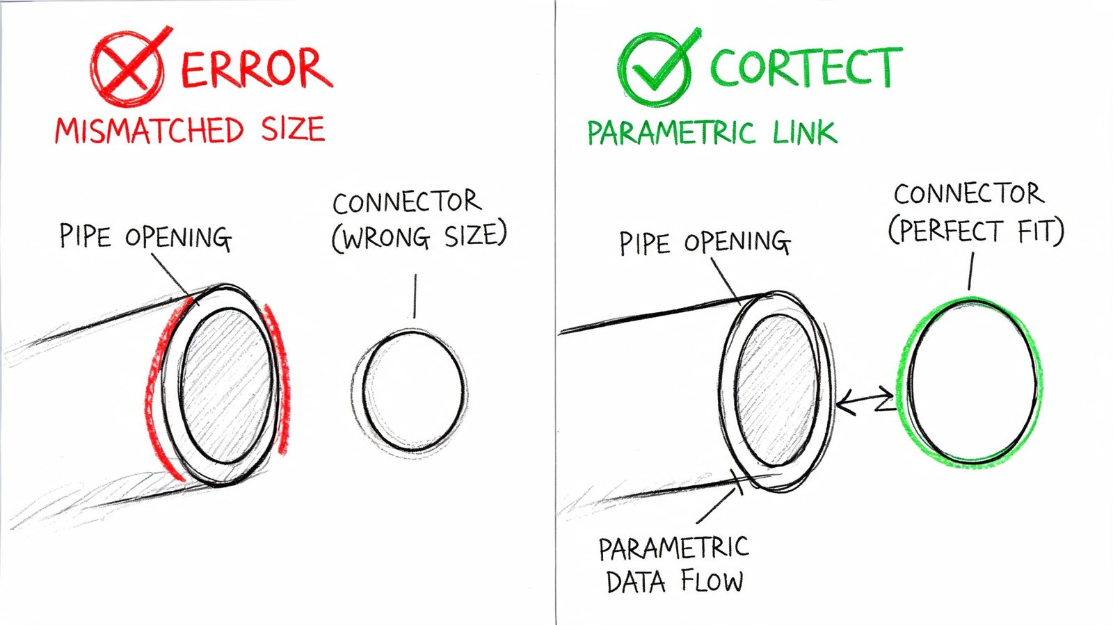
Connector dimensions need to read from the same parameters driving the geometry. If the extrusion flexes but the connector stays fixed, Revit sees two different parts: one you can see, and one it is trying to calculate and connect.
That is why a fitting can appear fine at its default type and then fail on the next job.
A common example is a rectangular duct fitting built at 24×12. The geometry is tied to Width and Height, but the connector was typed in manually during family creation. At 24×12, nobody notices. Change the type to 18×10 and the solids resize while the connector still reports 24×12. The join either refuses, inserts a transition nobody asked for, or creates a connection that behaves unpredictably later.
What the defect looks like
| Family type | Typical error | Project symptom |
|---|---|---|
| Duct fitting | Width and height hardcoded on connector | Revit will not connect to resized duct without adding a transition |
| Pipe fitting | Nominal diameter fixed instead of parameter-driven | Matching pipe size refuses to join |
| Flex connection family | Connector radius not linked to type parameter | Geometry shows one size, connector reports another |
This is not a geometry problem. It is a parameter mapping problem.
In production, I treat connector sizing as a family-editor issue first, not a model issue. If a family only connects at one size, the project file is usually innocent. The connector is reading the wrong parameter, or no parameter at all.
How to wire the connector correctly
Open the family. Select the connector itself, not just the visible geometry. Then check the instance or type properties for the connector dimensions.
The connector width, height, radius, or diameter should point to the same family parameters controlling the connection face. If the face is driven by Width and Height, the connector should also be driven by Width and Height. If the family uses a lookup table or type catalog, confirm the connector is still tied back to the parameters populated by that table.
Many downloaded content libraries often break. The solids were made parametric later, but the connectors were left behind on fixed values. Teams cleaning up content libraries and documenting Revit family workflows should check connector parameters as part of every family review.
The flex test that exposes the lie
Static review misses this defect. Flexing the family finds it fast.
- Open the Family Types dialog.
- Set the smallest expected size.
- Set the largest expected size.
- Select each connector and verify its reported dimensions at both extremes.
- Load the family into a test project and connect it to real duct, pipe, or equipment.
If the geometry changes and the connector values do not, the family is not ready for production.
This issue wastes time because it stays hidden until someone uses a non-default size. Then it shows up as a connection failure, a forced transition, or a sizing conflict that appears to come from the model. The underlying fix is usually back in the family editor, where the connector should have been tied to the geometry from the start.
Correcting Connector Origin Placement Errors
A connector can have the right classification, the right flow direction, and the right size, and still fail because it's sitting in the wrong place.
The hidden gap problem
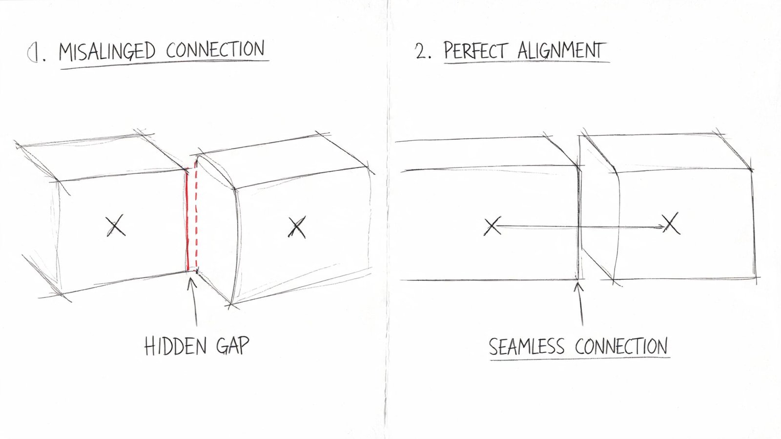
The connector origin must land exactly where the physical connection occurs. If it's offset inside the family, Revit can create a visual join that isn't a clean data join.
This is why some families "snap" but still leave open connectors in inspection tools or produce odd behavior in the system tree.
Typical causes include:
- Connector placed on a centerline instead of the end face
- Geometry moved during a later edit, but the connector stayed behind
- Duplicate connectors stacked at the same point in a poorly cleaned manufacturer family
How to fix it without guessing
Use a section or elevation inside the family editor. Don't try to judge this in a coarse 3D view.
Check these conditions:
- The connector origin sits exactly at the geometry face
- The connector is hosted or aligned to the same reference planes driving that face
- There are no redundant connectors occupying the same location unless the family needs them
A good family doesn't rely on visual closeness. It relies on exact placement.
When a connector origin drifts off the face, the project inherits a false connection. That's why the issue feels random in the model and obvious in the family editor.
This is one of the most common reasons an MEP family Revit object looks valid but leaves a ghost problem in the browser.
Aligning Connector Domain with System Type
Domain mismatch is a silent failure. Revit often won't throw a useful warning. The family loads, places, and may even appear to align correctly. It just doesn't behave as part of the system.
Where this usually happens
This shows up most often in multi-service equipment families. Someone copies a connector to save time, edits a few visible properties, and forgets that the domain still belongs to the original service.
A few common examples:
- A hydronic connection copied from an HVAC connector and never changed fully
- An electrical connector duplicated into a mechanical family variant
- A cable tray or conduit related connector carrying the wrong underlying domain
The check that prevents the silent miss
Review each connector independently. Don't infer anything from neighboring connectors.
- HVAC domain must align with HVAC system use
- Piping domain must align with piping system use
- Electrical domain must align with electrical connections
- Cable Tray/Conduit domain must align with those system types
If the domain is wrong, classification won't save it. Revit won't build valid Revit MEP system connectivity across a mismatch.
The main reason this survives QA is that many teams check what the family looks like before they check what the connector is.
Understanding System Families vs Loadable Families
A system looks fine in plan, then one VAV, valve, or boot refuses to join cleanly. Teams often start pulling apart duct types, pipe types, or routing preferences because the failure shows up in the run. That usually sends the investigation to the wrong place.
For connector failures, system families are usually the host environment. Loadable families are usually the source.
System families are the built-in Revit elements such as ducts, pipes, conduit, cable tray, and wire. They carry route behavior, segment rules, and type-driven system behavior inside the project.
Loadable families are the authored components that connect to those systems. Fittings, equipment, air terminals, plumbing fixtures, and specialty devices all fall into this category. Their connectors are defined in the Family Editor, which is why that editor should be the first stop when a system breaks at a specific component.
That distinction matters because Revit can only solve system continuity with the information the connector gives it. If the connector is classified correctly, oriented correctly, sized correctly, and placed correctly, the system family usually behaves. If that connector is wrong, changing project-side settings often turns into wasted hours.
Use a simple triage rule.
| If the break happens at | Check first |
|---|---|
| Straight run behavior across many instances | Type settings and routing preferences |
| One fitting, device, or equipment connection | The loadable family connector in Family Editor |
| The same manufacturer part failing repeatedly | A family-level audit before it enters production |
I treat this as a diagnostic inversion. Instead of chasing the visible break in the project model, go back to the family that owns the connector and test the failure there. It is faster, and it isolates the actual defect before it spreads into schedules, system browser organization, and coordination. If the project is already throwing warnings, run that family through your standard Revit error review process while you check the connector setup.
A Practical Audit for MEP Family Connectors
A system run connects everywhere except one VAV box, one valve, or one fixture. That is usually not a project-model problem. It is a family connector defect, and the fastest way to find it is to open the family first.
The audit sequence worth standardizing
Run this check before any family enters production, especially manufacturer content. The goal is simple. Prove that the connector can carry system logic correctly before the family ever touches a live model.
Confirm connector count
Match the connector count to the actual device. No spare connectors buried in geometry. No missing service connection that forces a workaround later.Check connector purpose
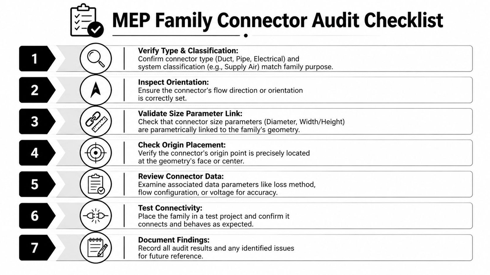
Review each connector for type, system classification, and domain. I check them one at a time because one wrong connector can make a family look correct in plan while still breaking system assignment.Inspect orientation
Verify facing and flow direction in the Family Editor. A connector can be classified correctly and still fail because it points the wrong way or reports flow opposite to the intended service.Validate size association
Make sure diameter, width, height, or radius are tied to the same parameters driving the visible geometry. If the connector sizes independently, schedules and connections drift apart fast.Review origin placement
Cut section views through the connection point. Look for connectors placed slightly off-center, recessed past the face, or stacked on duplicate origins. Those small placement errors cause repeated snap and routing failures.Test in a clean project
Load the family into a blank file, connect it to a basic run, and check the System Browser result. If warnings show up during the test, run the family through your Revit error review process while you inspect the connector setup.Document the result
Record what was fixed, what limits still exist, and which approved version goes into the library. That prevents the same bad family from getting reintroduced under a different filename.
Why this audit saves time
This process works because it isolates the fault at the object that owns it. Teams lose hours trying to repair connectivity from the project side by changing routes, redrawing runs, or swapping system types, when the actual issue sits inside one loadable family. Open the family, verify the connector logic, then test it in a clean file. That sequence is faster and gives a clear pass or fail result.
The downstream impact is bigger than one bad connection. A defective connector can break system grouping, corrupt schedule behavior, and push coordination teams to solve a geometry problem that is really a data problem. Clean family content reduces that noise before it reaches production.
For firms that need outside help setting up those controls, options include internal content standards, consultant-led QA, and services such as BIM Heroes, which supports template management, BIM consulting, and model coordination for production teams.
Clean system behavior starts in the Family Editor. The project model should confirm connector performance, not discover basic connector defects.
The teams with the fewest recurring MEP connectivity problems treat family QA as production control. If Revit MEP family errors are breaking system trees on a live project, a targeted family audit usually fixes the cause faster than another round of project cleanup. BIM Heroes helps AEC teams review and clean up Revit families, including manufacturer content that looks correct but fails at the connector level.