Meta description: Learn how to produce a reflected ceiling plan Revit users can issue with confidence. Improve ceiling grid control, annotations, soffit detailing, and MEP coordination to reduce contractor RFIs.
The sheet looked clean. The contractor still couldn't build from it.
There was no grid control point. Fixtures were shown, but not located in a way an installer could lay out with confidence. The diffuser shown on the architectural RCP didn't match the mechanical drawing. A soffit appeared in plan, but no one could find its height without digging through sections. By the time the site team calls, the field is making decisions that should have been resolved in the office.
That's the primary problem with many reflected ceiling plan Revit workflows. The drawing can look complete and still fail as a construction document. A buildable RCP has to answer installation questions directly, not indirectly. If it doesn't, the contractor fills in the gaps, and that usually means RFIs, redesign in the middle of construction, or avoidable field coordination.
Production discipline is vital. Strong RCP construction documents Revit teams don't treat reflected ceiling plans as presentation sheets. They treat them as coordination sheets with installation consequences.
The Unbuildable RCP A Common Field Problem
A reflected ceiling plan only works if the contractor can lay out the ceiling without guesswork. That sounds obvious, but many RCP failures come from a basic mismatch between what designers think they issued and what installers require.
Historically, reflected ceiling plans became an important coordination drawing because they show the ceiling as if mirrored onto the floor, keeping ceiling and floor orientation aligned and easier to read. That convention is widely used to document lighting, diffusers, sprinklers, and other overhead systems without crowding the floor plan, as noted in this explanation of reflected ceiling plan conventions.
A contractor doesn't care that the sheet is graphically tidy if the layout can't be started. A foreman needs fixed references, coordinated device locations, and unambiguous heights. If any of those are missing, the field starts interpreting design intent. Once that happens, control of the result moves off the model and onto the jobsite.
What makes an RCP buildable
A buildable RCP usually comes down to three things:
- A start point for the grid: The installer needs to know where the ceiling grid begins relative to a fixed building reference.
- Locations for overhead devices: Lights, diffusers, speakers, detectors, and similar elements need to be tied to the grid or to fixed dimensions.
- Clear ceiling elevations: Every change in plane needs to be identified where the contractor is looking for it.
Practical rule: If the field has to infer layout logic from a combination of plan, section, and consultant drawings, the RCP isn't finished.
That's the standard production teams should hold.
What Contractors Actually Need From an RCP
A ceiling crew shows up at 6:00 a.m., snaps lines, and stops within an hour because the plan gives them no defensible layout point. The architect thought the sheet was clear. The foreman sees three possible interpretations and sends an RFI. That is not a field problem. It is a production problem.
Contractors use the RCP to set out work, sequence trades above the ceiling, and verify what can be installed without rework. If the drawing leaves layout logic, device position, or height changes open to interpretation, the field fills in the gaps. Once that happens, coordination moves from the model to the jobsite, where every correction costs more.
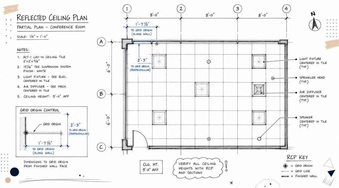
Give the installer a real layout origin
Grid direction is only part of the instruction. The crew also needs the point where the layout starts, tied to something that will not move: a structural grid intersection, column centerline, or finished face that is already controlled in the field.
Show that origin in both directions with dimensions that can be pulled on site. If the room relies on “center the grid in the space” without a controlling reference, the result will drift room by room. The drawing may still look orderly. The installation will not.
Show how each overhead item relates to the ceiling system
An installer does not place lights and devices by visual balance. They place them by rule. On a gridded ceiling, the rule might be centered in tile, aligned to a T-bar, or offset one module from grid center. On a hard-lid ceiling, it should be fixed from walls, grid lines, or another permanent control.
That relationship has to be explicit for lights, diffusers, access panels, speakers, detectors, and sprinkler heads. The common failure is showing each trade's element in the same area without declaring which item owns the centerline, which item shifts, and which coordination decision was approved. That is where avoidable RFIs start.
Put ceiling changes and heights on the plan where the work is being laid out
Contractors should not have to assemble ceiling intent from a plan, two sections, and separate consultant sheets. If the ceiling steps, slopes, drops, or turns into a soffit, tag the height and identify the condition at the plan location. If a specialty ceiling changes material, support method, or access requirements, call that out where the installer will see it during layout.
If the field has to compare multiple sheets just to confirm one ceiling plane, the RCP is still carrying unresolved coordination.
A buildable RCP gives the crew enough information to lay out the ceiling, place the overhead work, and understand every change in plane before anyone starts cutting grid or framing bulkheads. That is the standard. Anything less only pushes design decisions downstream.
Common Revit Modeling Errors That Create Unbuildable RCPs
Most bad RCPs aren't ruined by annotation. They're ruined upstream, in the model. The sheet exposes the problem, but the model created it.
Wrong ceiling heights that still look right in plan
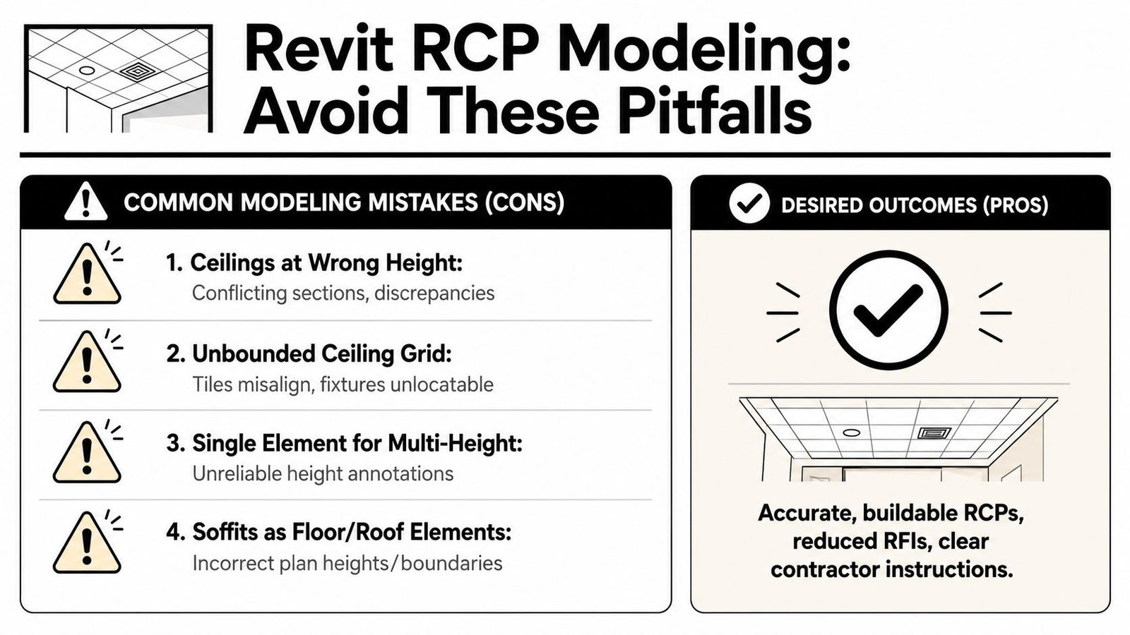
This is one of the most common failures in reflected ceiling plan Revit production. A ceiling can appear fine in plan while carrying the wrong height parameter. The tag might be corrected manually, or the team may not notice because the plan “looks right.”
Then the section disagrees. The elevation disagrees. The soffit clearance doesn't work. The field catches the mismatch and asks which drawing governs.
If you want reliable RCPs, stop trusting appearance. Audit the actual ceiling element parameters before sheets are assembled.
One ceiling element trying to do too much
Each ceiling plane at a different height should be its own ceiling element. Teams that try to force multiple height conditions into one edited element usually create unreliable tags, messy boundaries, and section graphics that don't communicate intent clearly.
A stepped ceiling needs explicit control. Separate elements give you cleaner tags, clearer boundaries, and fewer surprises when views update.
Ceiling grid not aligned to room geometry
A ceiling grid that isn't laid out with room logic breaks the installation logic of the entire drawing. The room may read cleanly on the sheet, but tile edges drift in ways that make fixture placement difficult to rationalize. The result is a grid that can't be used to locate devices cleanly.
That becomes a bigger problem in tenant improvement work, where room proportions are tight and every tile matters.
Fake soffits built with the wrong category
Teams sometimes model soffits as floors, roofs, or generic workarounds because it helps in 3D or gets a visual result faster. That shortcut usually fails in RCP views. Boundaries read incorrectly, height information gets muddy, and view behavior becomes inconsistent across the set.
If an element won't schedule, tag, and display consistently in the view type where it matters, it's the wrong modeling strategy.
That's where production maturity shows up. Not in clever workarounds. In model choices that survive documentation.
Setting Up Your RCP View Range and Graphics in Revit
A standard floor plan view is a bad starting point for RCP production. It carries the wrong assumptions and usually the wrong graphics. If your office template treats reflected ceiling plans like modified floor plans, the team is working harder than it should.
Fix the view range first
The cut plane needs to capture the ceiling conditions you're documenting. If the view range is still set like a typical plan, you'll clip ceiling geometry and spend time chasing display problems that are really setup problems.
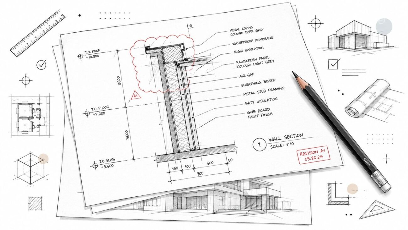
Use an RCP-specific template. Set the cut plane high enough to capture soffits and ceiling edges consistently. Keep the view depth low enough to preserve the wall and room context needed for orientation. The exact setup varies by project, but the principle doesn't. The view has to be built for the ceiling, not inherited from a floor plan.
If your team needs a stronger template baseline, this guide on Revit view range setup is a useful internal standard to align around.
Build graphic hierarchy, not graphic noise
The ceiling grid should read lightly. Walls and room boundaries should carry more visual weight. Device symbols need to be legible without overpowering the grid they relate to.
That hierarchy belongs in the view template and visibility settings, not in manual overrides applied one sheet at a time. Manual cleanup hides template weakness. It also creates inconsistency across delivery teams.
A dependable setup usually includes:
- Lighter ceiling grid lines: The grid should support layout, not dominate the sheet.
- Visible and consistent ceiling tags: Every ceiling element that matters in construction needs to tag correctly.
- Controlled consultant links: Linked MEP content should be visible only to the extent needed for coordination and annotation support.
Match the annotation crop to the actual view
This sounds minor until you issue a set and realize dimensions or tags are cut off on the sheet. Annotation crop and model crop need to work together. If they don't, the team ends up nudging tags and dimensions manually, and that creates fragile sheets that break during later revisions.
A good RCP view should survive viewport movement, annotation updates, and late coordination changes without falling apart graphically.
Dimensioning and Annotating RCPs for Field Execution
The RCP looks clear in the office. Then the ceiling crew gets to site and asks the question the sheet should have answered already. Where does the layout start, and what controls the fixture locations? If the drawing leaves either point open to interpretation, the installer makes the decision in the field, and the RFI comes later.
Dimension the grid origin from a field reference
Start with the one dimension that establishes the ceiling layout. Show where the first full tile or grid module begins from a reference the field can find and trust. Column grid intersections, concrete lines, and finished wall faces that are already locked work well. Centerlines of partitions that may shift during fit-out do not.
That single dimension sets the installation logic. Without it, every other dimension on the sheet becomes less reliable because the contractor is still guessing at the starting point.
Show fixture placement as installation intent, not graphic suggestion
Fixtures, diffusers, speakers, access panels, and detectors need location logic that can be measured. On a gridded ceiling, indicate whether the item is centered in tile, aligned to a grid line, or intentionally offset. On a hard-lid ceiling, use centerline dimensions from fixed building references.
Do not rely on symbolic placement alone. A family that looks centered on screen can still be wrong for field execution if the host condition changes, the ceiling edge shifts, or the device was aligned to an unstable reference during modeling.
For teams tightening annotation standards, these rules for accurate CAD dimensioning translate well to RCP production because the same field risk applies. Ambiguous dimensions get interpreted in the field.
Tag every ceiling height change the installer will encounter
Installers do not build a “main ceiling.” They build each change in plane. Every soffit, bulkhead, cloud, recessed area, and local hard-lid condition needs a finished height tag tied to the correct element. If a transition matters to framing, grid, or device alignment, it belongs on the sheet.
A good review pass checks three things:
- Base ceiling heights are tagged and match the model parameters
- All local drops, raises, and transitions carry their own heights
- Unusual geometry points to sections, enlarged plans, or details where the field can see how it is built
The goal is simple. A foreman should be able to lay out the ceiling without calling the design team to ask what was intended.
Mastering MEP Coordination for Reflected Ceiling Plans
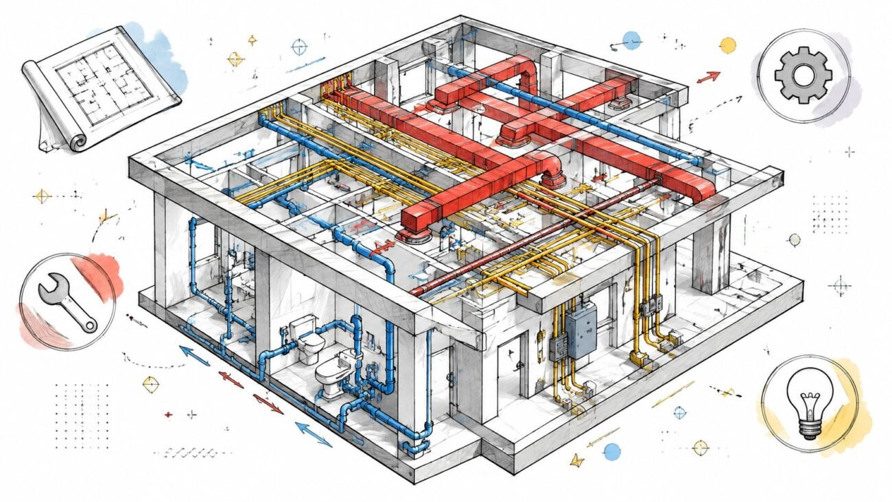
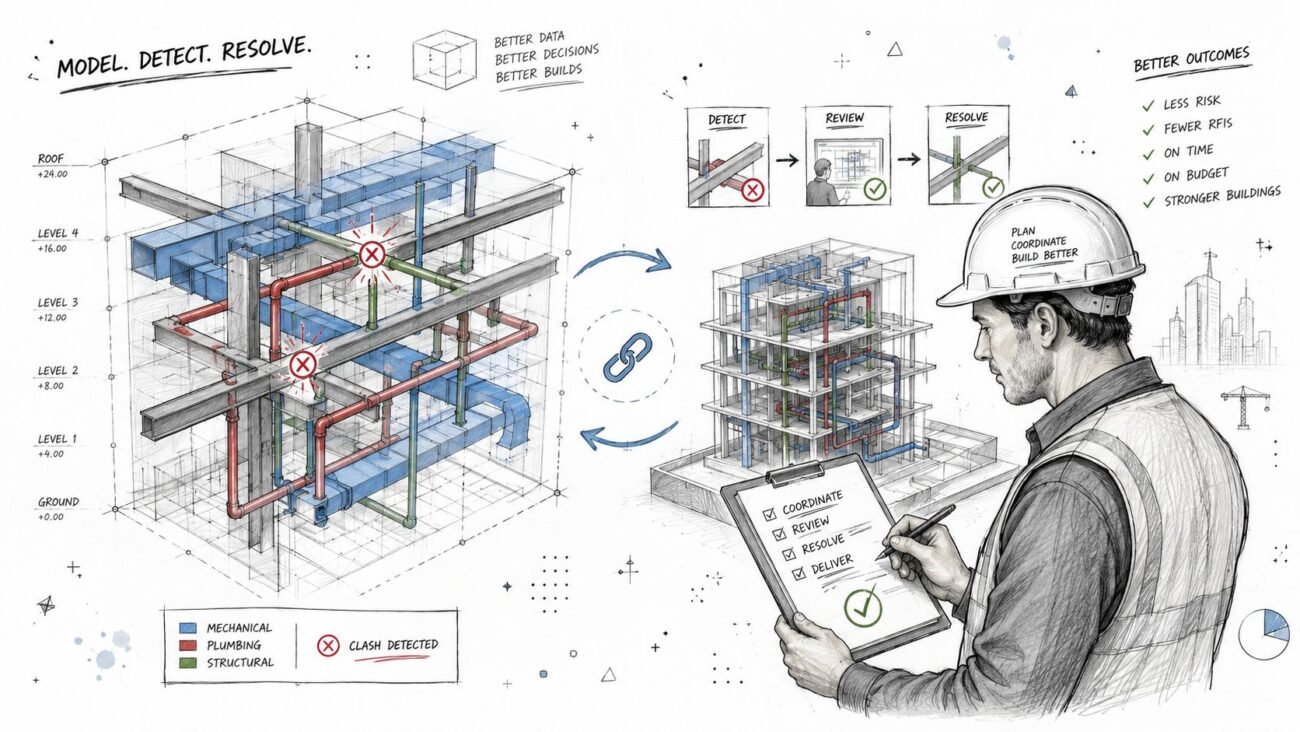
The ceiling is one of the densest coordination zones in the project. Architectural, mechanical, electrical, and fire protection all want the same physical space. If teams treat the RCP as a downstream documentation task, coordination failure is almost guaranteed.
A key gap in most public RCP guidance is coordination risk. Many explainers describe what appears on the drawing, but not how teams prevent clashes and late rework when multiple trades occupy the same ceiling zone. That issue is highlighted in this article on reflected ceiling plan coordination risk.
Reconcile diffusers before issue
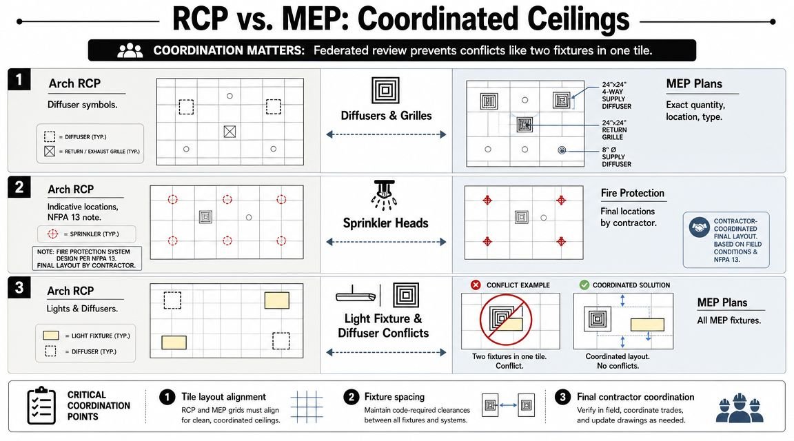
An architectural RCP that shows diffuser locations different from the mechanical plan is asking the contractor to choose which consultant to trust. That's not acceptable. Quantity, approximate location, and type intent need to align before the sheet is issued.
This gets missed often when architecture and MEP work in separate models and no one runs a proper federated review before the deadline.
Handle sprinkler information carefully
Show sprinkler heads as coordinated with the ceiling layout, but don't imply final placement authority if the contractor will complete final fire protection coordination. The note should make that responsibility clear and align with project requirements. The point is to communicate design intent without pretending the architectural sheet controls final fire protection layout where it does not.
Check one tile, one decision
A basic conflict still gets missed too often. One tile cannot host a centered troffer and a centered diffuser at the same time. The same applies to speakers, detectors, access panels, and other devices competing for limited tile real estate.
Run a coordination review that overlays the architectural ceiling grid with all ceiling-mounted MEP devices. In practice, that means federated checking in Revit, Navisworks, or a similar coordination workflow. If your team is building repeatable delivery pods, resources such as this plenum and ceiling coordination article can help formalize review routines. The tool matters less than the discipline. The clash has to be found before the sheet goes out.
Detailing Soffits and Specialty Ceilings Correctly
Soffits and specialty ceilings are where weak reflected ceiling plans are exposed fast. A simple grid room can survive limited annotation. A ceiling transition cannot.
What every soffit must show
At minimum, each soffit needs three things in the document set:
- A plan boundary: The contractor needs to know exactly where the soffit begins and ends.
- A height annotation: The bottom elevation has to be stated clearly.
- A section or detail reference: The installer needs to see how it's built, not just where it sits.
If one of those is missing, the drawing is incomplete.
Cloud ceilings and custom systems need two levels of documentation
The RCP should show the overall boundary and elevation of a cloud or specialty ceiling system. The supporting detail should show the assembly, support logic, and interface with adjacent surfaces. Don't try to make the plan do the work of a detail.
That separation keeps the sheet readable and keeps the construction information usable.
Transitions are where RFIs start
The junction between a grid ceiling and a drywall soffit needs more than linework. The RCP should identify the transition point and the height of each adjacent plane. The detail should show how the junction is resolved.
If cove lighting is part of that soffit, the architectural intent also has to align with the electrical drawings for fixture type, circuiting, and switching. Otherwise the soffit becomes a shape with no buildable lighting scope attached to it.
A soffit in plan with no detail reference isn't a finished document. It's an unfinished question.
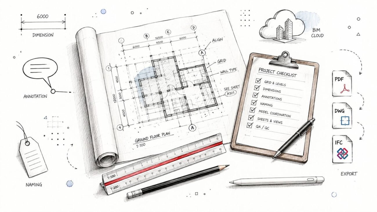
An RCP Pre-Flight Checklist to Prevent Common RFIs
The RCP usually looks fine right before issue. Then the field asks the questions the team should have caught in thirty seconds. Where does the grid start. Which ceiling height governs at this transition. Is that diffuser centered on the room, the tile, or the light run. Those RFIs rarely come from a lack of design intent. They come from weak production control.
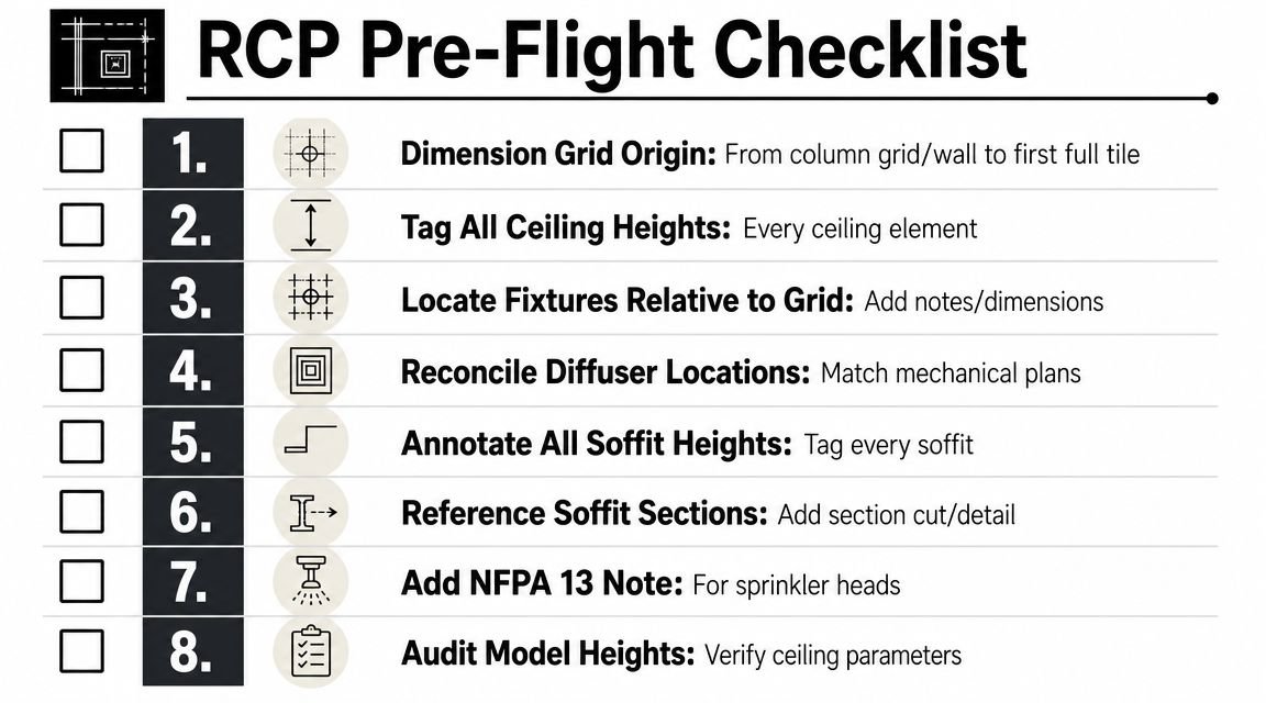
Run a final RCP review before every issue, and treat it like a buildability check, not a graphic polish pass. The goal is simple. Confirm that a contractor can lay out, coordinate, and install the ceiling without calling the architect to interpret the drawing.
Keep the review short and repeatable. A production lead, BIM coordinator, or senior architect should be able to open the sheet and answer the field's likely questions fast.
Use this checklist before release:
- Grid origin dimensioned: Confirm dimensions from a fixed building reference to the first full tile or control line.
- Ceiling heights verified: Check that every ceiling condition is tagged and that the tagged value matches the model parameter.
- Fixture layout defined: Verify that lights, diffusers, access panels, and devices are tied to grid logic or fixed dimensions.
- Consultant coordination checked: Compare architectural layout intent against mechanical, electrical, and fire protection drawings for conflicts or unexplained offsets.
- Perimeter conditions resolved: Confirm edges, partial tiles, bulkheads, and ceiling transitions are clear at walls and room breaks.
- Soffits and special ceilings complete: Make sure plan extents, elevations, and referenced details are all present.
- Responsibility notes included where needed: State delegated coordination items clearly, especially for sprinkler heads and specialty systems.
- View and sheet limits reviewed: Check crop regions, annotation crops, dependent views, and hidden elements so no tag, note, or reference is cut off.
- Keynotes and references tested: Make sure every section, detail, and callout points to a placed and relevant drawing.
- Sheet-to-sheet consistency checked: Verify the RCP agrees with enlarged plans, interior elevations, finish plans, and reflected details.
Teams with mature production standards do this every time. Teams without them issue sheets that still need to be interpreted in the field.
If your team needs help tightening reflected ceiling plan Revit standards, building stronger QA checkpoints, or scaling RCP production without losing consistency, BIM Heroes provides Revit production support for architectural documentation. A practical next step is to review their architectural production services and compare your current RCP workflow against a more disciplined delivery model.