A roof plan goes out for permit. It shows the roof outline, RTU locations, and a general note that says “slope to drain.” It comes back redlined. No slope annotation. No drain locations. No curb dimensions. No parapet height. No roof access hatch. The drawing looked complete in a quick internal review, but it didn't communicate enough for the reviewer to verify drainage, maintenance access, or coordination.
That kind of correction isn't a drafting mistake. It's a production failure. A permit-ready roof plan has to work as a coordination document, not just a sheet that shows what sits on top of the building. If your team is also thinking through field risk, contractor liability, or rooftop maintenance exposure, practical references like this 2026 guide to roofer insurance help frame why roof documentation needs to be explicit, not implied.
Introduction
Most permit comments on roof plans are predictable. Reviewers flag what the drawing leaves ambiguous. If the roof drains, they want to see how. If equipment sits on curbs, they want to verify what those curbs are. If people need to service rooftop units, they want to see how those people get there and move safely once they're on the roof.
For commercial work, that means your roof plans need to show more than the perimeter and a few tags. In professional AEC documentation, the roof plan must communicate the roof perimeter, slope, dimensions, overhangs, and penetrations such as skylights, vents, and drainage elements, with flat roofs showing drainage gradients and pitched roofs showing clear slope indicators for downstream coordination, as noted by Vectorworks on roof plan documentation.
What a Permit-Ready Roof Plan Must Show
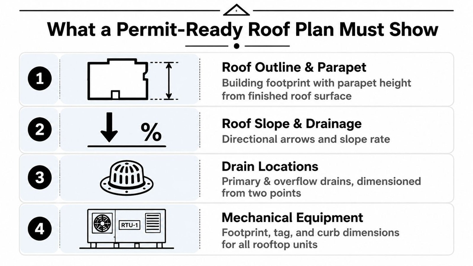
A complete commercial roof plan is a verification tool. The reviewer should be able to trace water movement, locate every drain, understand the roof edge condition, and identify every rooftop element without hunting through five other sheets.
If that sounds basic, it is. It's also where a lot of roof plan construction documents Revit teams still miss permit comments.
Start with the roof edge and parapet
Show the full roof outline at the roof level. If the building has a parapet, show it clearly and annotate parapet height from finished roof surface, not from the level datum. That distinction matters because the reviewer is checking the built condition at the roof, not your internal modeling reference.
A parapet tag with no reference basis is weak documentation. A section can support it, but the roof plan should still carry enough information to avoid an RFI.
Practical rule: If the parapet height affects edge protection, overflow, screening, or visibility, put it where the roof plan reviewer can find it immediately.
Show slope and drainage direction
A note that says “slope to drain” doesn't prove anything. Add slope arrows and annotate the slope rate at each roof area. On low-slope work, especially where tapered insulation creates the drainage pattern, the arrows are what turn design intent into a readable permit document.
The history matters here. Low-slope roofs became practical during the Industrial Revolution, and the National Roofing Contractors Association defines a low-slope roof as no greater than 25% slope, equivalent to 3 inches of rise per 12 inches of horizontal run, according to CCPIA's history of low-slope roofs. That's useful context because many “flat” commercial roofs are only flat in casual conversation. In drawing terms, they still need explicit drainage logic.
If you work on mixed-use or residential-over-podium projects, homeowner-facing explainers like these roof pitch insights for homeowners can be useful for client conversations, but permit drawings need a stricter level of annotation than those simplified summaries.
Dimension drains and show overflow
Every primary roof drain should be shown and dimensioned from two reference points. The same goes for overflow drains or scuppers. If the plan only shows primary drains, it reads incomplete because the reviewer can't confirm the overflow path.
Use a consistent dimensioning method:
- Grid intersection to drain centerline for larger commercial buildings
- Face of parapet to drain centerline where the geometry is simple
- Secondary reference from a perpendicular wall, curb, or structural line
Teams issuing permit sets can tighten this process with a dedicated permit drawing workflow so drain layouts, references, and annotation standards don't change from project to project.
Show rooftop equipment as built objects, not symbols
RTUs, exhaust fans, cooling towers, skylights, and any other roof-mounted item need a footprint, tag, and curb reference. Don't leave equipment as generic blocks with a keynote. If the object changes the roof membrane, framing, or access path, the roof plan has to show it at a level that supports review and coordination.
Documenting Rooftop Equipment and Penetrations
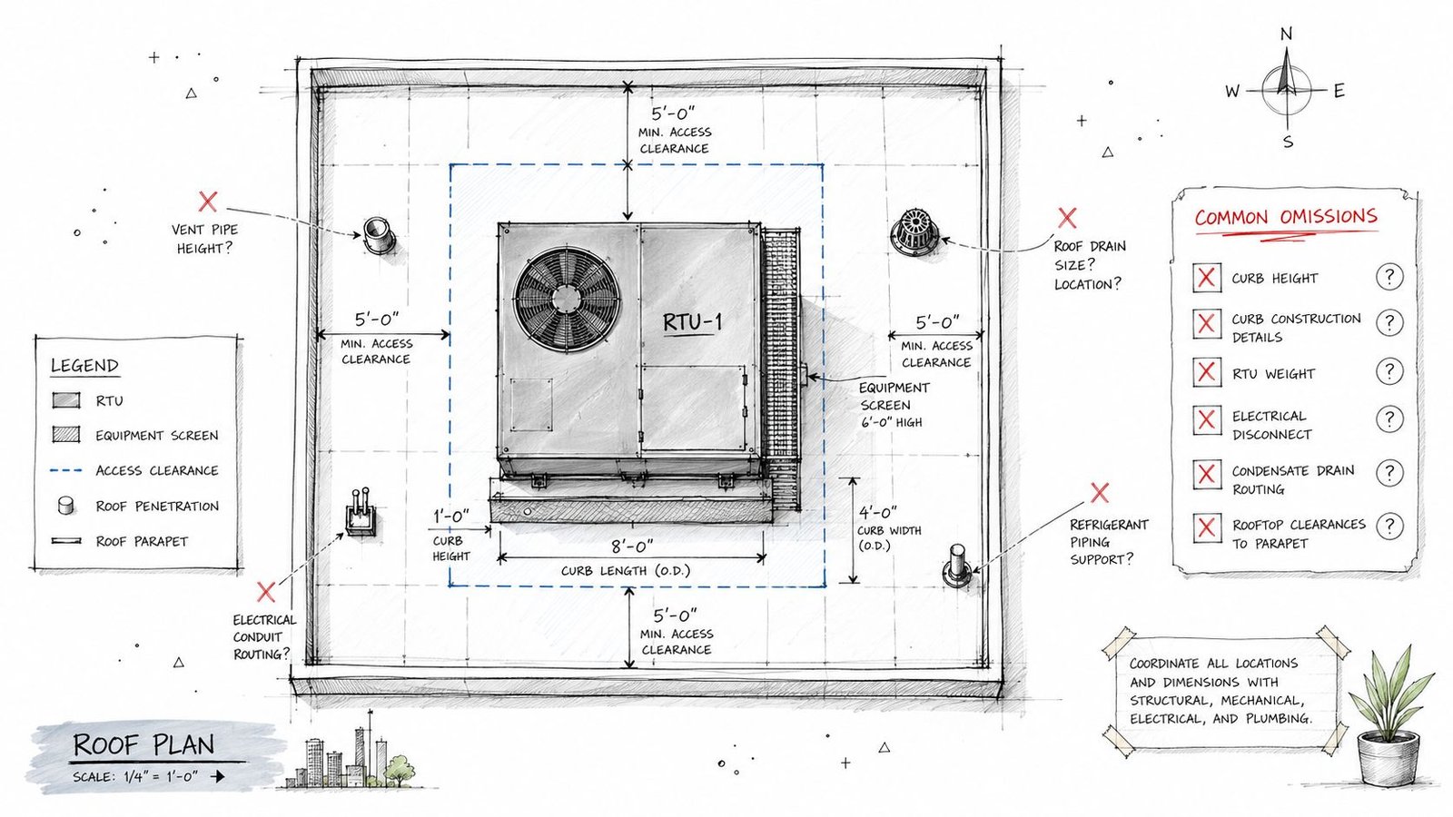
Many roof plans start falling apart when the equipment is visible but the documentation around it is thin. That gap doesn't show up as a graphic issue. It shows up later as field confusion, membrane conflicts, and last-minute coordination calls.
Curb dimensions have to be real
Every rooftop unit needs a curb. The curb dimensions need to appear on the roof plan or in a clearly referenced detail. If the equipment tag points to a schedule but nothing in the set confirms curb size, the installer is left to resolve it in the field.
That's not a small omission. A curb that doesn't match the equipment footprint or required base condition creates a direct construction problem.
Here's the minimum that should be verifiable:
- Equipment footprint shown at plan
- Unit tag matched to the mechanical schedule
- Curb dimensions on plan or by explicit detail reference
- Orientation confirmed so service side and connection side aren't guessed in the field
For replacement-heavy commercial work, this matters even more. In North America, roofing replacements account for 94% of total project volume and 91% of total value, and the U.S. roofing contractors industry is projected to reach $76.4 billion in revenue in 2025, with roofing products demand exceeding $23 billion in 2024, according to Roofing Insights industry statistics. Roof plans aren't a side issue in the market. They sit inside a large renewal-driven workflow where bad documentation gets expensive fast.
If your team handles retrofit or equipment swap scopes, examples from rooftop unit replacement projects are useful because they expose where existing curbs, access routes, and penetrations usually break coordination.
Clearance, screens, and penetrations need to align
Maintenance clearance around equipment has to be legible on the roof plan. If a screen wall appears on elevations, it also needs to show on the roof plan with dimensions and enough spacing information to verify the equipment isn't boxed into an unserviceable corner.
Penetrations are even less forgiving. Every pipe, conduit, duct, vent, and sleeve that crosses the roof membrane should be shown. Missing penetrations often mean the architectural roof plan and the MEP model are no longer describing the same roof.
The roof membrane doesn't care which discipline “owns” the penetration. It still has to be flashed, coordinated, and kept out of the drain field.
That coordination also affects specification logic. Technical roof specifications tied to roof plans commonly include wind-uplift design pressure calculations, membrane application sequencing, and underlayment requirements. One published standard calls for either a full self-adhered membrane over the roof deck or 4-inch deck flashing tape over sheathing seams, covered by #30 felt or equivalent synthetic underlayment in high-wind conditions, as described in Building Enclosure guidance on roof specifications.
When details call for specialized edge or penetration accessories, teams often review product options such as Dek Cap flashing boxes during detailing coordination. The point isn't the product itself. It's making sure the roof plan identifies the penetrations early enough that the detailing package can keep up.
Detailing Roof Access and Safety
A roof full of serviceable equipment without a documented access route is incomplete. Reviewers notice it, contractors notice it, and facility teams definitely notice it after turnover.
Show the access point like it matters
If the project uses a roof hatch, show the hatch location and dimension it from two reference points. Include the hatch size and tie it to a detail or specification. Don't leave access implied by a note in a life safety sheet or by a symbol in a background view.
Where serviceable rooftop equipment is present, access also has to connect back to code logic in sections and plans. The means of getting to the roof can't disappear between disciplines.
A clean access package usually includes:
- Hatch or stair location with dimensions
- Opening size called out at plan
- Associated detail reference to the architectural detail set
- Section confirmation showing the vertical access condition
Walkpads and service routes are part of the design
Rooftop walkpads protect the membrane from repeated maintenance traffic. If the access point is shown but the service path is not, you've only documented half the use case.
Draw walkpads from the access point to every maintainable piece of equipment. Call out the walkpad material and keep the route intentional. Random patches near equipment don't communicate circulation.
Field lesson: If a technician can't see the intended route on the drawing, they'll make one with their boots.
Fall protection belongs on the roof plan
If maintenance personnel are working near an unprotected roof edge, the roof plan needs to identify the fall protection approach. Depending on the project, that may be a guardrail, warning line, or anchor system coordinated with the structural and safety strategy.
This is one of the easiest places for architectural sheets to drift away from real use. A roof plan that treats maintenance as someone else's problem usually produces RFIs later. The safer approach is to document where people go, what they service, and how edge exposure is handled in the same roof-level coordination package.
Setting Up Your Roof Plan View in Revit
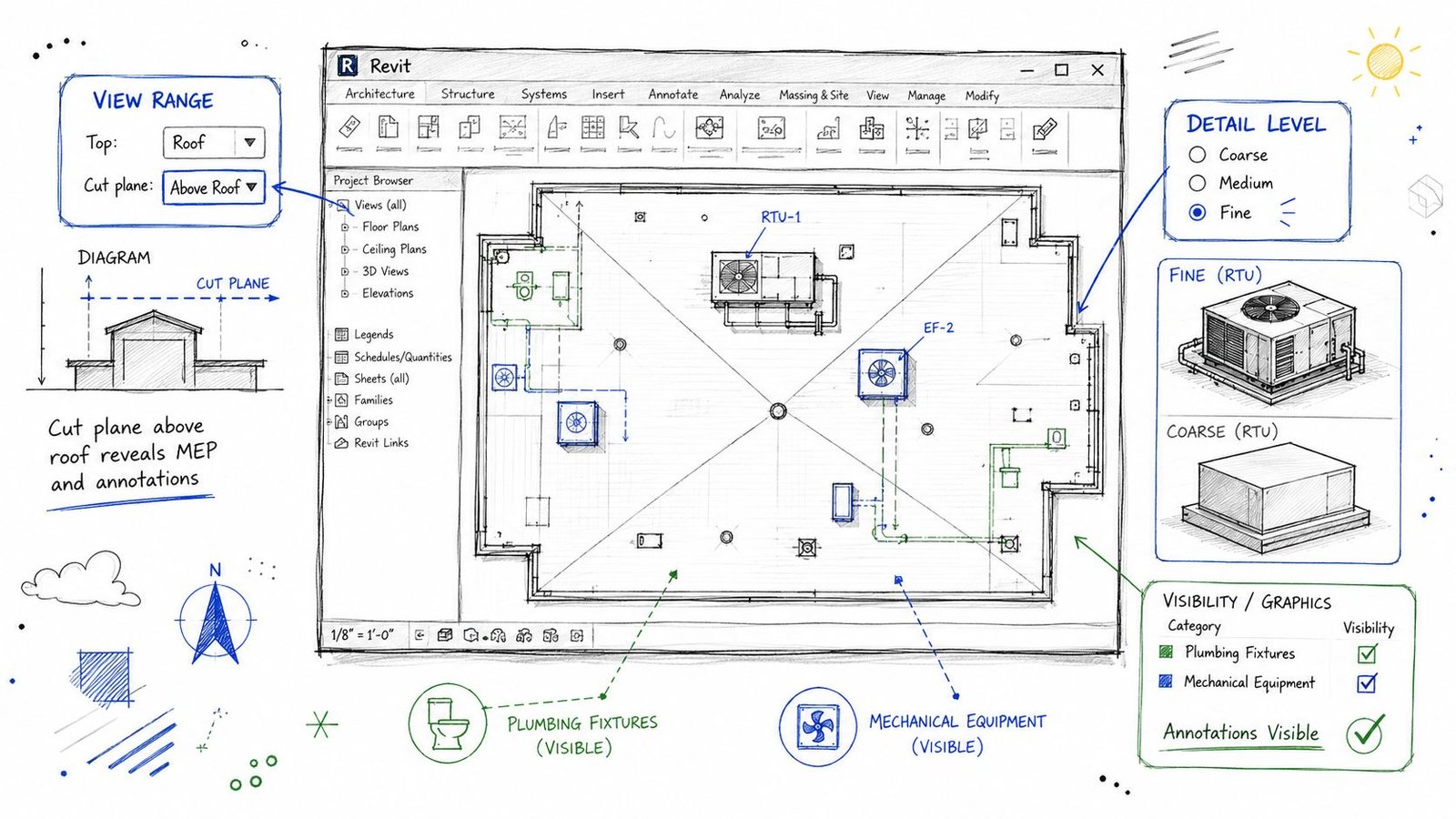
A lot of bad roof plans start with a bad view. Teams try to annotate their way out of a weak Revit setup, and the result is a sheet that looks patched together. If the view doesn't expose the right geometry, annotation becomes inconsistent and QA turns into cleanup.
Fix the view range first
Set the roof plan view range so the cut plane reads the rooftop condition properly. If the cut plane sits at a default floor plan height, the model often shows roof elements as projection instead of cut geometry. That makes parapets, curbs, and some roof-mounted components harder to read and annotate accurately.
For permit work, the roof view should be tuned intentionally, not duplicated from a generic plan template. If your team needs a stable standard for this, a dedicated Revit view range setup guide helps lock down repeatable settings.
Use this check before annotation starts:
| Item | What to verify |
|---|---|
| Cut plane | High enough to cut relevant rooftop elements |
| Top and bottom extents | Broad enough to include parapets and roof-mounted objects |
| View depth | Controlled so hidden elements don't muddy the drawing |
Don't annotate in Coarse detail
Set Detail Level to Fine for roof plans intended for permit and coordination. Coarse views often suppress geometry you need, especially around rooftop equipment and drain bodies.
That's where teams lose time. They think the equipment family is missing, but it's really just not displaying with enough detail for plan annotation.
A dependable roof plan view in Revit usually has:
- Fine detail level for equipment and drains
- Consistent lineweights for cut versus projection
- Filters or view templates that preserve category visibility
- Discipline-specific overrides only where necessary
Check categories before you blame the model
Roof drains are often modeled under Plumbing Fixtures. Rooftop equipment may live in Mechanical Equipment or Electrical Equipment. If those categories are off in the architectural roof plan view, the sheet will look incomplete even when the model contains the right elements.
This is a frequent source of false coordination issues. The object exists. The view just isn't built to show it.
Review these visibility settings every time:
- Plumbing Fixtures
- Mechanical Equipment
- Electrical Equipment
- Generic Models, if custom curb or accessory families are in use
- Links and linked view display, if MEP content is referenced from linked models
Use shape editing when roof geometry gets messy
Irregular roofs expose weak Revit habits fast. Practitioners regularly run into obtuse intersections, mixed pitches, and “strange rooflines” when relying too heavily on the first sketch. The more dependable workflow is to edit the roof and use split lines or shape editing tools rather than expecting the initial footprint to solve everything, as discussed in the Autodesk Revit forum thread on obtuse roof sketches.
That advice matters because roof plan permit requirements don't stop at simple geometry. If the model can't produce clean edges, drain paths, and accurate boundaries, the drawing won't survive documentation.
Clean roof plans come from stable model logic. If the geometry is unresolved, annotation only hides the problem for a while.
Coordinating Roof Plans Across Disciplines
A roof plan isn't an isolated architectural sheet. It's the roof-level handshake between architecture, structure, MEP, and civil. When that handshake is weak, field questions multiply.
Structural coordination starts with location, not afterthoughts
Show the structural grid on the roof plan when equipment placement depends on framing below. Heavy curbs, concentrated loads, and openings need to be checked against the framing plan before issue.
A curb that lands in the wrong place may still look fine on the architectural roof plan. It only becomes a problem when the structural team points out the support condition doesn't work, or worse, when the contractor discovers it after steel or joists are set.
Good coordination review asks:
- Does the curb align with the structural bay?
- Is there adequate framing support below?
- Do roof openings interfere with joists, beams, or bracing?
MEP and plumbing coordination should be literal
The equipment shown on the roof plan should match the mechanical schedule in both type and location. If the schedule lists one unit and the roof plan tags another, someone will issue an RFI. The same applies to drain layouts. The roof plan should align with the plumbing design intent, not approximate it.
Roof pitch becomes more than graphics. Roof pitch is a systems and compliance issue, not just a drawing convention. Public guidance commonly notes that asphalt shingles are typically used at minimum slopes around 2:12 to 4:12, while low-slope conditions call for materials such as EPDM or TPO, as outlined in roof pitch guidance from Roof Measuring. On commercial work, that decision affects membrane selection, drainage detailing, and what each discipline needs to coordinate at the roof edge and drain field.
Civil input closes the loop
Drain locations on the roof plan should align with the drainage strategy being carried through the rest of the project. Civil, plumbing, and architectural teams may each touch a different piece of that system. The permit set works better when one roof plan becomes the shared roof-level reference rather than a diagram that each discipline interprets differently.
That's the bigger production point. Roof plans that pass permit cleanly usually come from firms that treat them as coordination checkpoints, not annotation exercises.
A QA Checklist for Common Roof Plan Errors
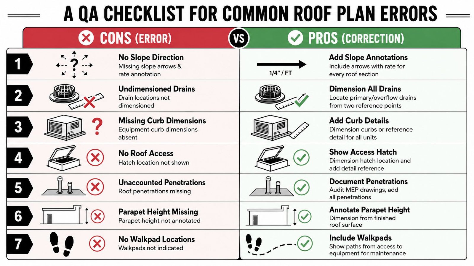
Before issue, run the roof plan through a short QA pass that focuses on permit comments you can predict. This isn't redline theater. It's a disciplined check that keeps preventable corrections out of the submittal cycle.
The fast review list
Use this as a final sheet-level audit:
Slope direction missing
Add slope arrows and slope rate annotation to every roof area that drains.Primary drains shown but not located
Dimension every primary drain from two reference points.Overflow path omitted
Show overflow drains or scuppers and locate them with the same discipline as the primary system.Curb dimensions absent
Add curb dimensions directly on the roof plan or tie each unit to a referenced curb detail.Roof hatch not documented
Show hatch location, size, and detail reference. Make sure the section set reflects the means of access.Penetrations missing from the architectural plan
Compare the roof plan against MEP sheets and linked models. Add every duct, vent, pipe, and conduit that penetrates the membrane.Parapet height not tied to the roof surface
Annotate parapet height from finished roof surface, not from a generic level datum.Walkpads not shown
Draw maintenance routes from the roof access point to all serviceable equipment.
What catches issues fastest
A useful QA sequence is simple:
Review the roof plan without schedules.
If the sheet can't explain itself visually, it isn't ready.Overlay MEP and structural references.
Look for curbs, penetrations, and openings that drifted.Check annotation against model categories.
Missing objects are often view setup problems, not modeling problems.Read it like a permit reviewer.
Ask whether water flow, equipment support, and maintenance access can be verified from the issued set.
Most roof plan corrections aren't caused by difficult design. They're caused by missing decisions, hidden in plain sight.
The strongest production teams don't rely on memory for this. They bake roof plan permit requirements into templates, view standards, annotation families, and QA checklists so every project starts from the same operating logic. That's how roof plans become consistent across pods, offices, and project types.
If your team needs help tightening commercial CD output, BIM Heroes supports Revit production for permit sets with a focus on documentation clarity, coordination discipline, and scalable delivery. If a roof plan checklist, template standard, or QA framework would help your team issue cleaner sheets, it's worth reaching out through their architectural production services page.